I would love to see how this comes out on a resin printer. I don’t have one, but I’m curious how functional you’ll find the parts with the light cured resins.
For the larger actuators, we may all need to help each other out on extending the small actuator design to the larger ones. The thought was to dial in the small actuator first and then scale it up to the larger ones. Getting close to that point now with this design getting so good.
I’ll let you know how I get on with the prints, I can use my fdm printer as a backup if it doesn’t work out in resin. I ordered a modified version of the pcbs tonight from jlcpcb (changed the resistors to 0603 and put them all on the same side to aid with hotplate assembly)
Yeah, in my next iteration of the board I want to allow for 1.27mm headers on the temperature and Hall sensors connectors on the PCB to reduce some of the room needed for the headers.
I also want to break out the remaining gpio to aux headers so we all have some future flexibility. I am now playing with an optical encoder for closed loop and don’t have a way to use the remaining gpio.
How much thought have you put into using Hall effect sensor for absolute position encoding? There are magnetic encoders with 4k-8k CPR. Others are using them for digital protractors built into a lathe compound.
As far as I can tell, magnet encoders need the magnet in the center. I can’t find one that would allow the magnet out at the outer diameter like where my hall sensor is. So, I can’t see a way to use these. If you got a dual shaft 35mm motor, you could measure the stepper motor movements, but I’d like to measure the outer ring movements after the reduction.
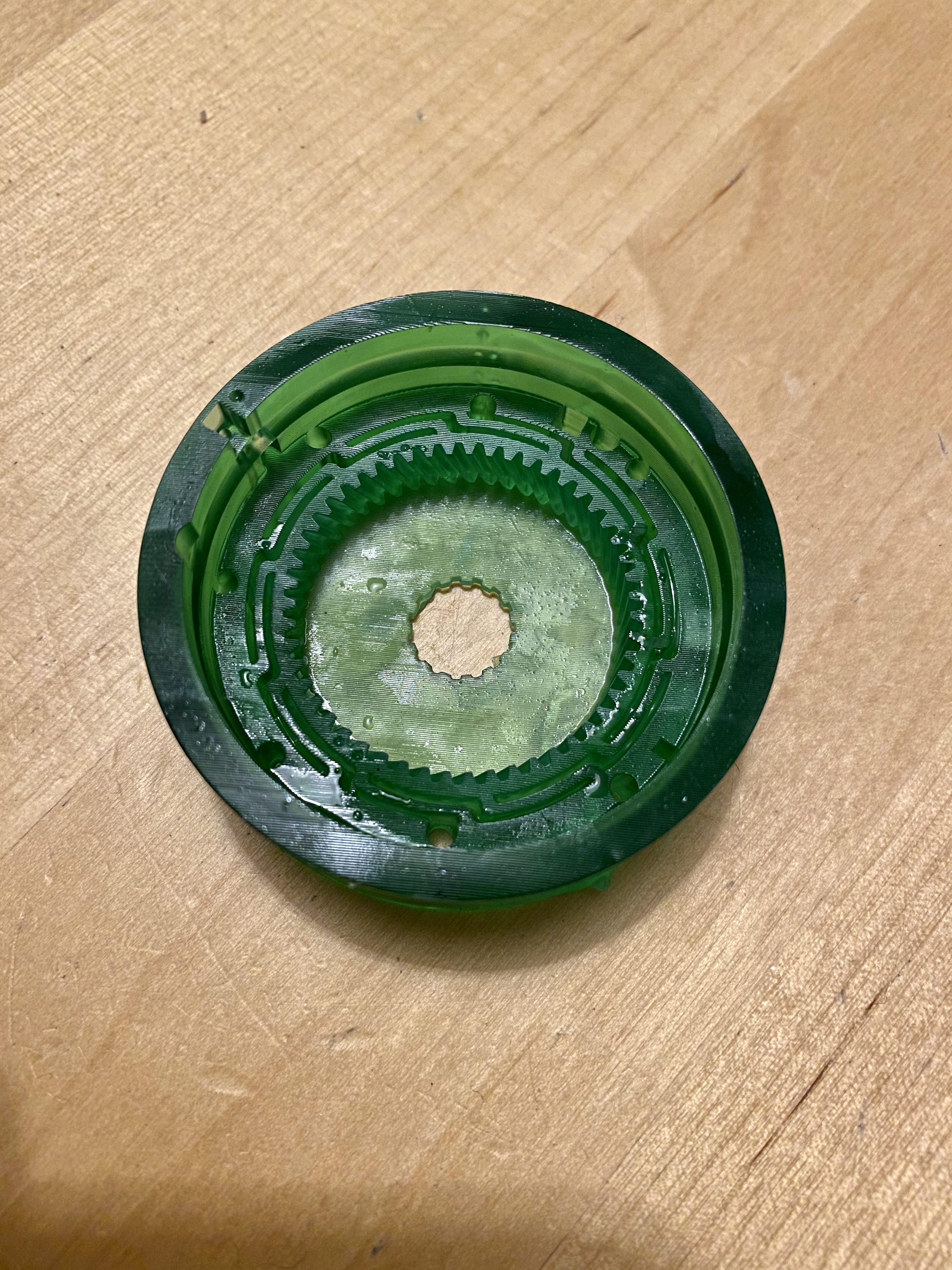
Wow! That is awesome seeing that done via resin. Now, I wonder how the mechanical nature of that flex spine will work out with the resin since PLA is nicely flexible.
It will flex when pushed with a finger, i’ve done one in pla on my FDM printer as well, just to compare. Just need the remaining bits to arrive from aliexpress, then I can get the gears in and try it out
I have the older code working now, still struggling with the new. My newer pcb with almost all smt on one-side was ok, the pad was not too close to the via. I have moved it a bit further away though, so i’ll get the pull request updated.
Wow! Is that flex spine gear printed via DLP process?
Really nice! only thing I would have concerns about would be that the hinges will keep the tension under torque without breaking. But the idea is great!
If my steppers could provide more torque this would be an idea to improve the toothplay of my gearchains, too.
Here’s a technique (not sized in this application for your needs!) that does not put the encoder at the center; it uses a ring-shaped diametric magnet:
Deciding on print settings and material for my final version of actuator prints. What is the max rpm that your code it going push the small actuators too? I want to test at that RPM.
I have a PLA version working fine, it takes a lot of gear tuning though.
I also got a 100% (Gears and body) Nylon version going, no work on the gears at all, works right out of the printer. I am leaning towards going 100% nylon for the actuators, for the finished product . Only concern is the collector arms are pretty flexible.
Can you foresee anything wrong with that?
Completed a couple proto runs on assembling the actuator circle, finally happy with my resistor soldering technique, and overall quality. Going to go into production on the boards for the finished product.
Looks like there has not been any changes to your design posted on Git Hub in the last two months, correct?
I tested the BOM motor from moons and from Ali, seemed like the motor from Ali got hotter, but also did not stall as often. I ran them both at 20V, did you wind up with a preference on motors between the two?
I found that I went back to PLA after trying PETG. Ultimately I think they both work fine. This actuator does not do high RPM. I’m more interested in precise movements anyway. On the final output I think you only end up with maybe max 20 RPM.
I have not posted much code lately as work has been consuming me, but it’s all up there for folks to play with and even modify or extend. I’m all for pull requests too.
On the motor getting hot, what current setting do you have it at on the DRV8825? I use a banggood power supply that shows me the mA and I would run the motors around 250 to 300mA.
Okay, I think I have good enough prototypes, had been testing them to 300 RPM, haha, any missteps/stalls were happening at over 200 RPMs. Was setting Vref to .4 so theoretically 800mA, will tune that down.
Thank you John.