The goal of this actuator is to create an open source 3D printable robot arm actuator with an open source PCB and open source software for an ESP32 to control the actuator. The actuator just needs 20V fed in through the slip rings so there are no wires. Communication across the actuators happens over wifi or Bluetooth so the signalling is wireless. Making progress, but still have a long way to go.
Yeah, it’s been some work, but not too bad. There are a lot of new ideas being worked on this actuator that I’ve not seen out there on the interwebs like the ESP32 driving it, or the Wifi, or the slip rings, or the touch sensors. The key as well is the 3D printable planetary gear. I think all of these combined could be a really great step forward. Just theory until it works though.
Here’s an update. I got Gcode working for the actuator with acceleration/deceleration working via the ESP32 RMT hardware. The goal is to be able to send Gcode to all 6 axes plus the end unit, so really 7 or even 8 axes of Gcode. That way the robot arm can move in a synchronized fashion from the Gcode.
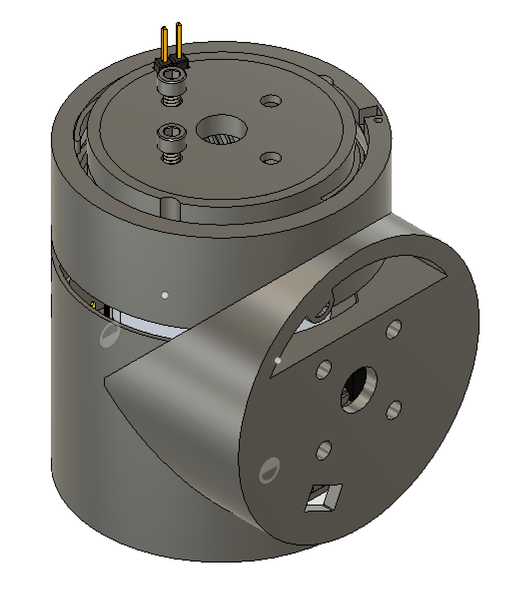
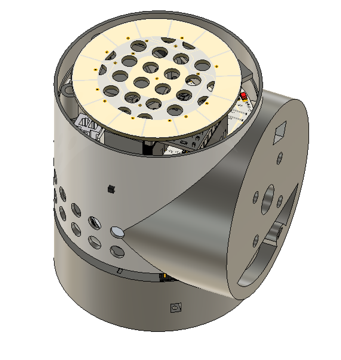
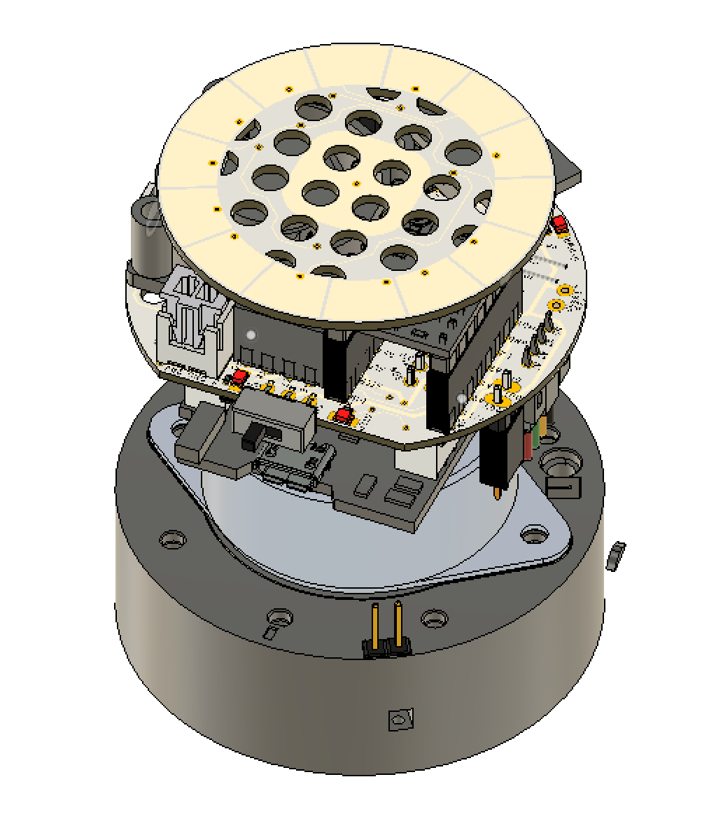
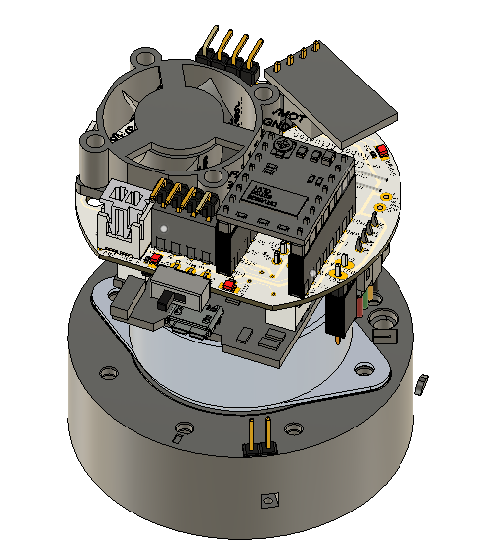
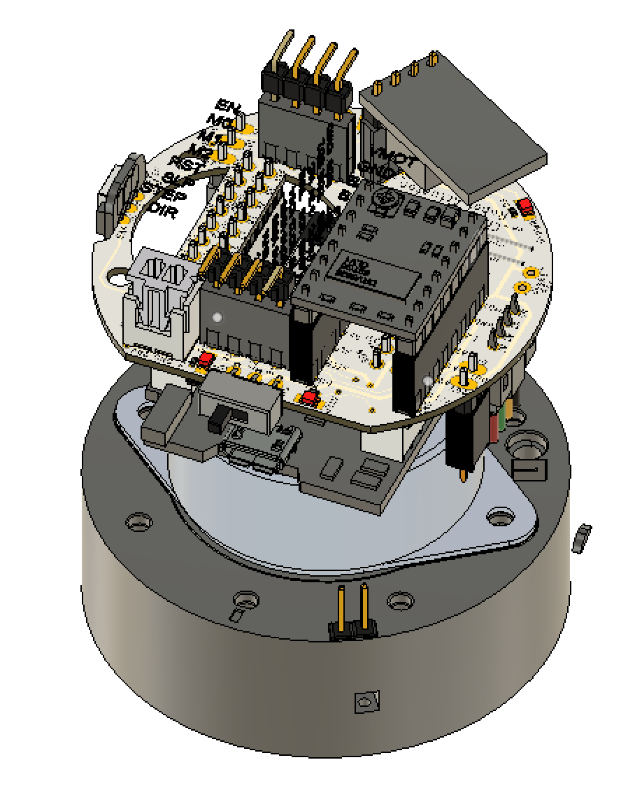
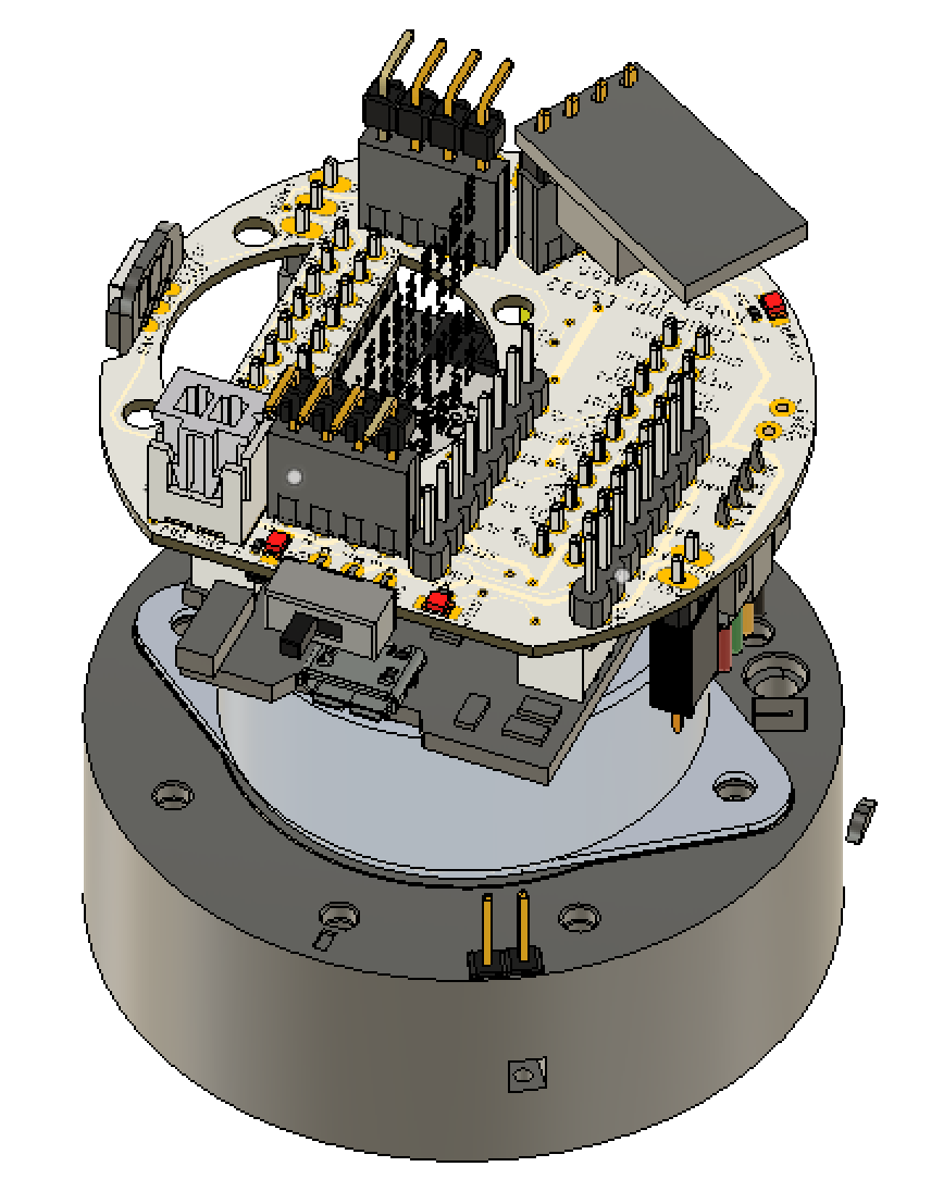
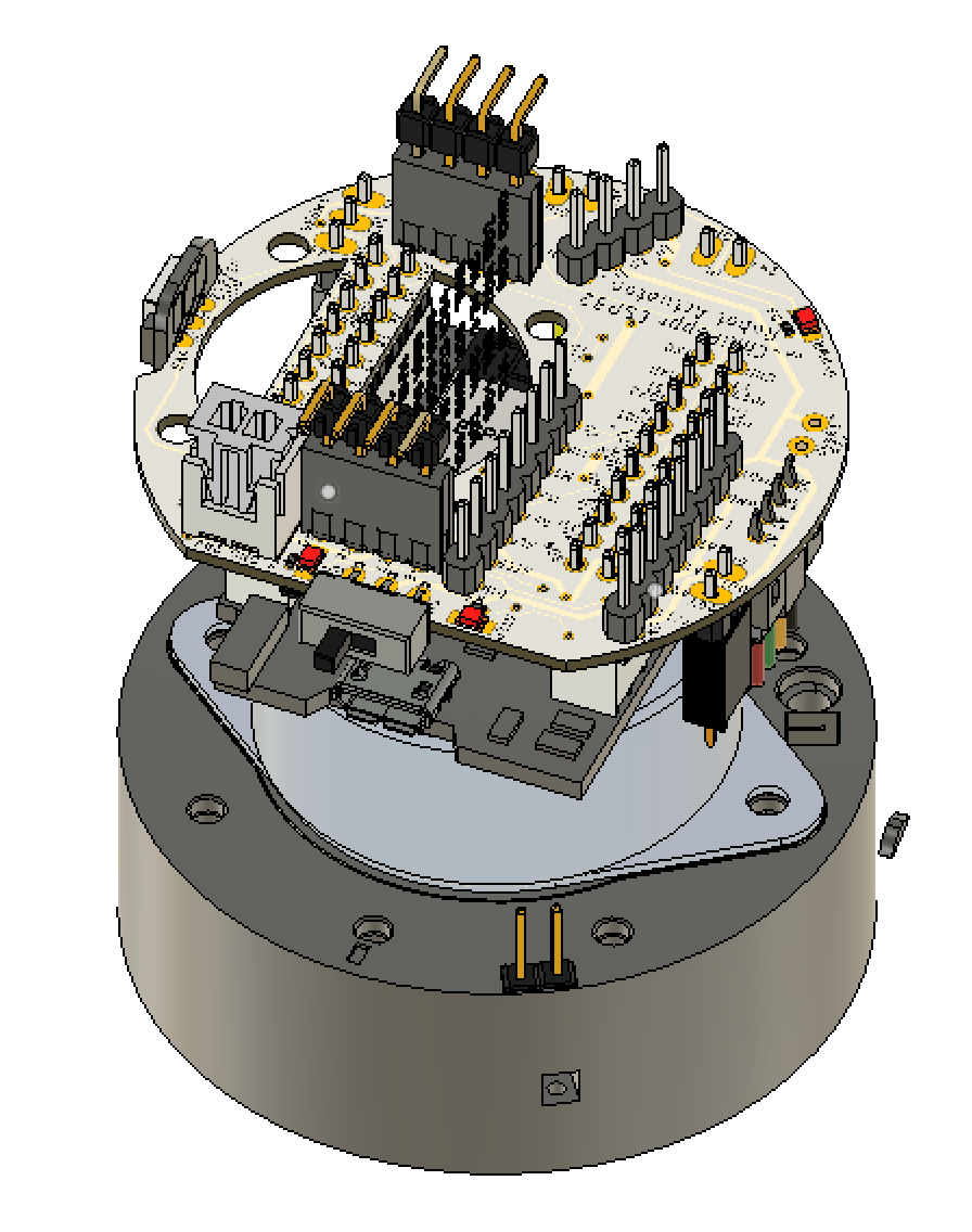
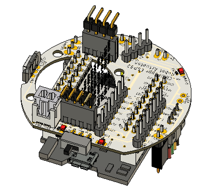
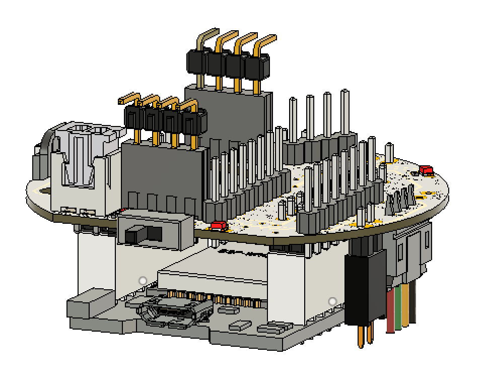
Latest version of my actuator. Took the anti-backlash small actuator design and tweaked it a lot. Tweaked the shell design a lot making it as wide as the anti-backlash case. Designed some custom PCBs. The coolest thing, I think, is the touch dial on the end. The next coolest is the slip ring to carry the 20v across actuators without wires. There’s a heatsink around the motor now, a 25mm fan PWM controlled from TMP36 temp sensor, and code to increase fan speed as motor heats up. From tests I can keep everything below 36 deg C permanently now. And you can train Gcode to the flash RAM of the ESP32 for later playback via the touch dial.
I’ll make a full Youtube video soon of the whole darn thing, but it’s rad.
Saw this on hackaday, really impressive thanks for sharing it.
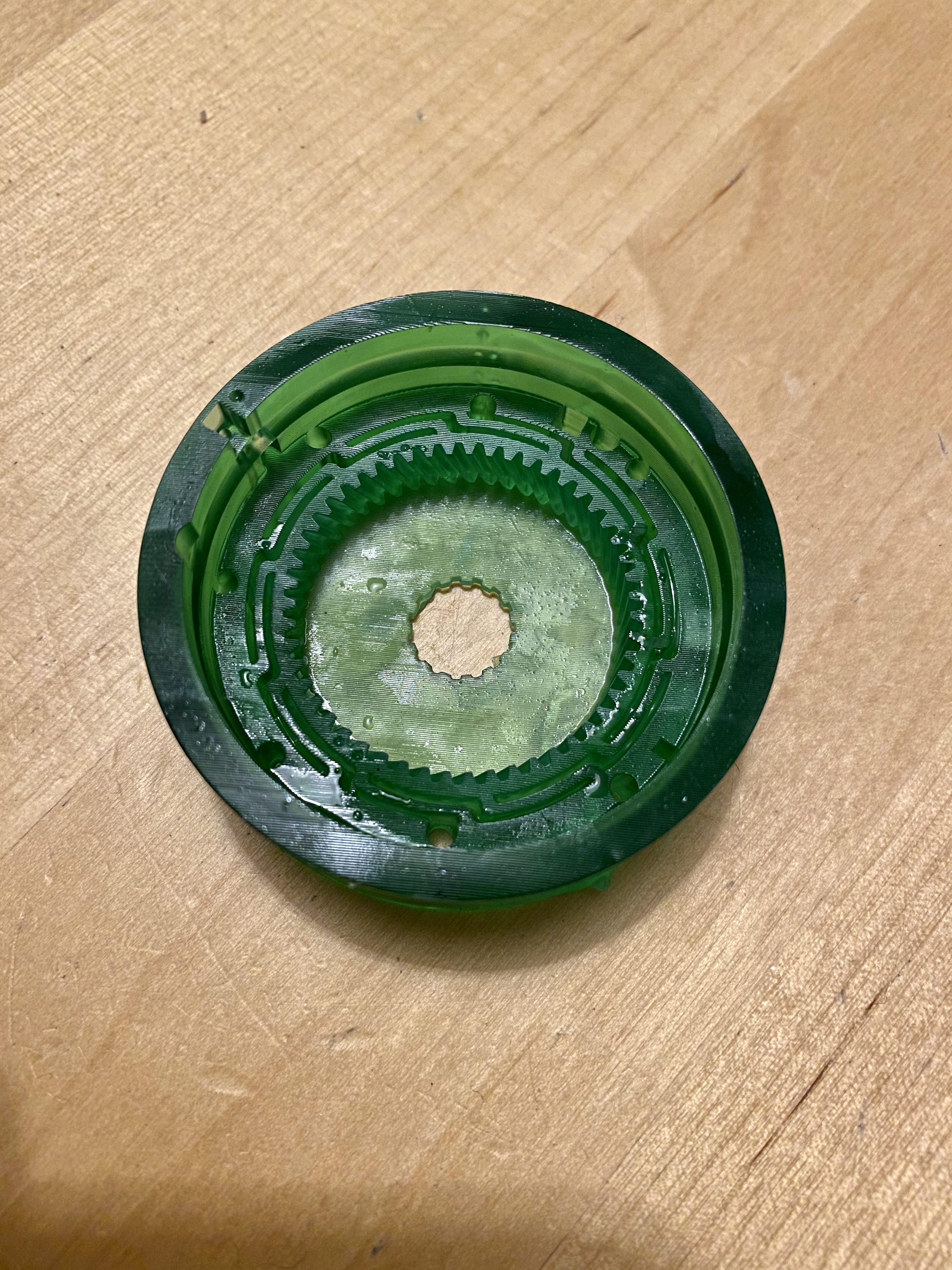
Looks like there is just enough space to print it on my resin printer.
Do you have any plans to enhance the larger bottom actuators of the original design in the future?
I would love to see how this comes out on a resin printer. I don’t have one, but I’m curious how functional you’ll find the parts with the light cured resins.
For the larger actuators, we may all need to help each other out on extending the small actuator design to the larger ones. The thought was to dial in the small actuator first and then scale it up to the larger ones. Getting close to that point now with this design getting so good.
I’ll let you know how I get on with the prints, I can use my fdm printer as a backup if it doesn’t work out in resin. I ordered a modified version of the pcbs tonight from jlcpcb (changed the resistors to 0603 and put them all on the same side to aid with hotplate assembly)
Yeah, in my next iteration of the board I want to allow for 1.27mm headers on the temperature and Hall sensors connectors on the PCB to reduce some of the room needed for the headers.
I also want to break out the remaining gpio to aux headers so we all have some future flexibility. I am now playing with an optical encoder for closed loop and don’t have a way to use the remaining gpio.
How much thought have you put into using Hall effect sensor for absolute position encoding? There are magnetic encoders with 4k-8k CPR. Others are using them for digital protractors built into a lathe compound.
As far as I can tell, magnet encoders need the magnet in the center. I can’t find one that would allow the magnet out at the outer diameter like where my hall sensor is. So, I can’t see a way to use these. If you got a dual shaft 35mm motor, you could measure the stepper motor movements, but I’d like to measure the outer ring movements after the reduction.
Wow! That is awesome seeing that done via resin. Now, I wonder how the mechanical nature of that flex spine will work out with the resin since PLA is nicely flexible.
It will flex when pushed with a finger, i’ve done one in pla on my FDM printer as well, just to compare. Just need the remaining bits to arrive from aliexpress, then I can get the gears in and try it out