@Mat_Helm
I saw “150mm on the Z.” and thought that was the Z movement. I didn’t notice they were referring to the length of their guide rails and just assumed that was their Z axis movement. Guide rail length is just not a specification I am too used to seeing so it threw me I suppose.
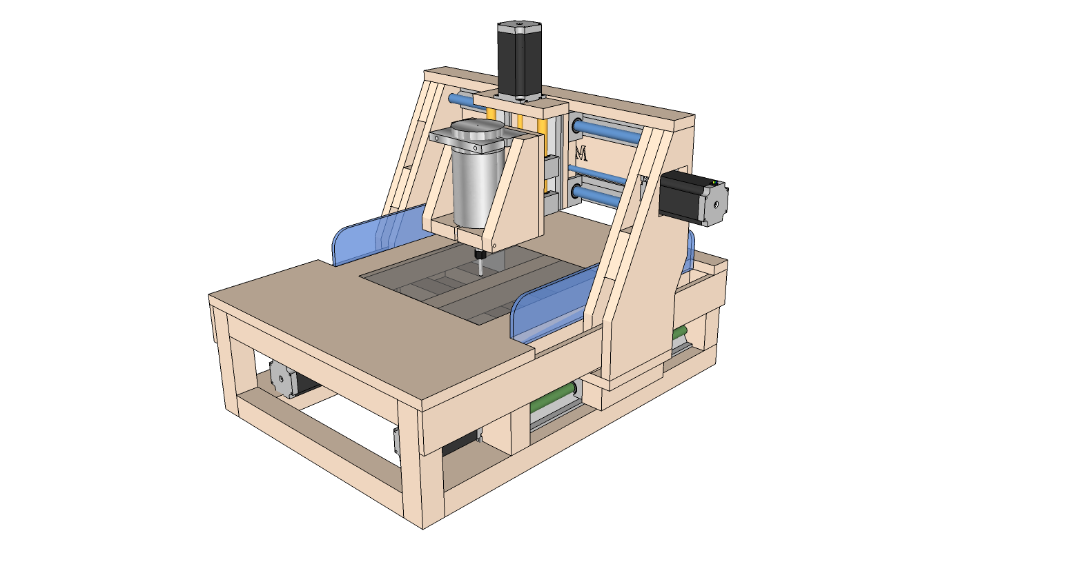
I’m sticking with an inch of useful travel though because bits have some length to them usually. For working with most sheet material it is fine.
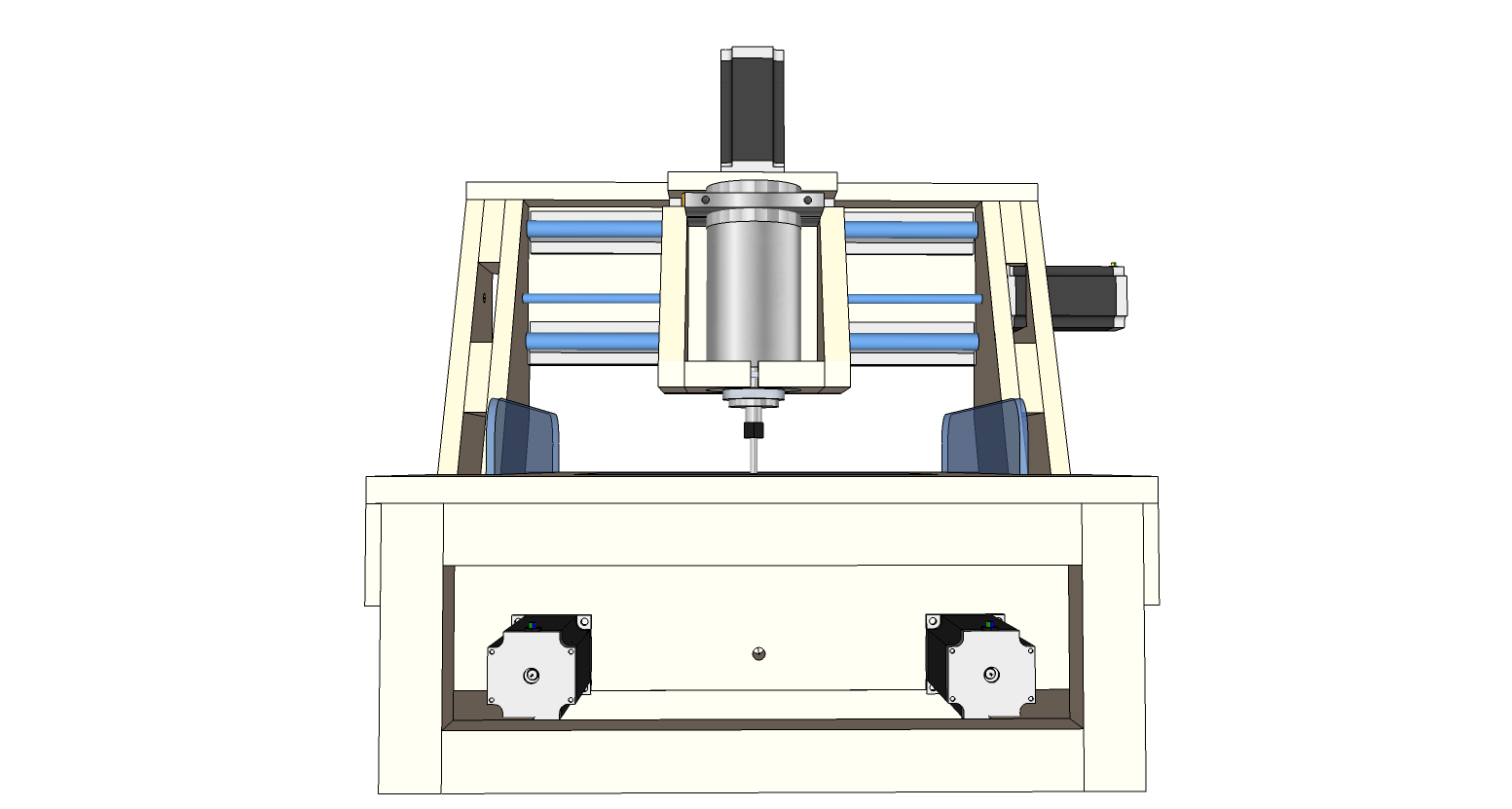
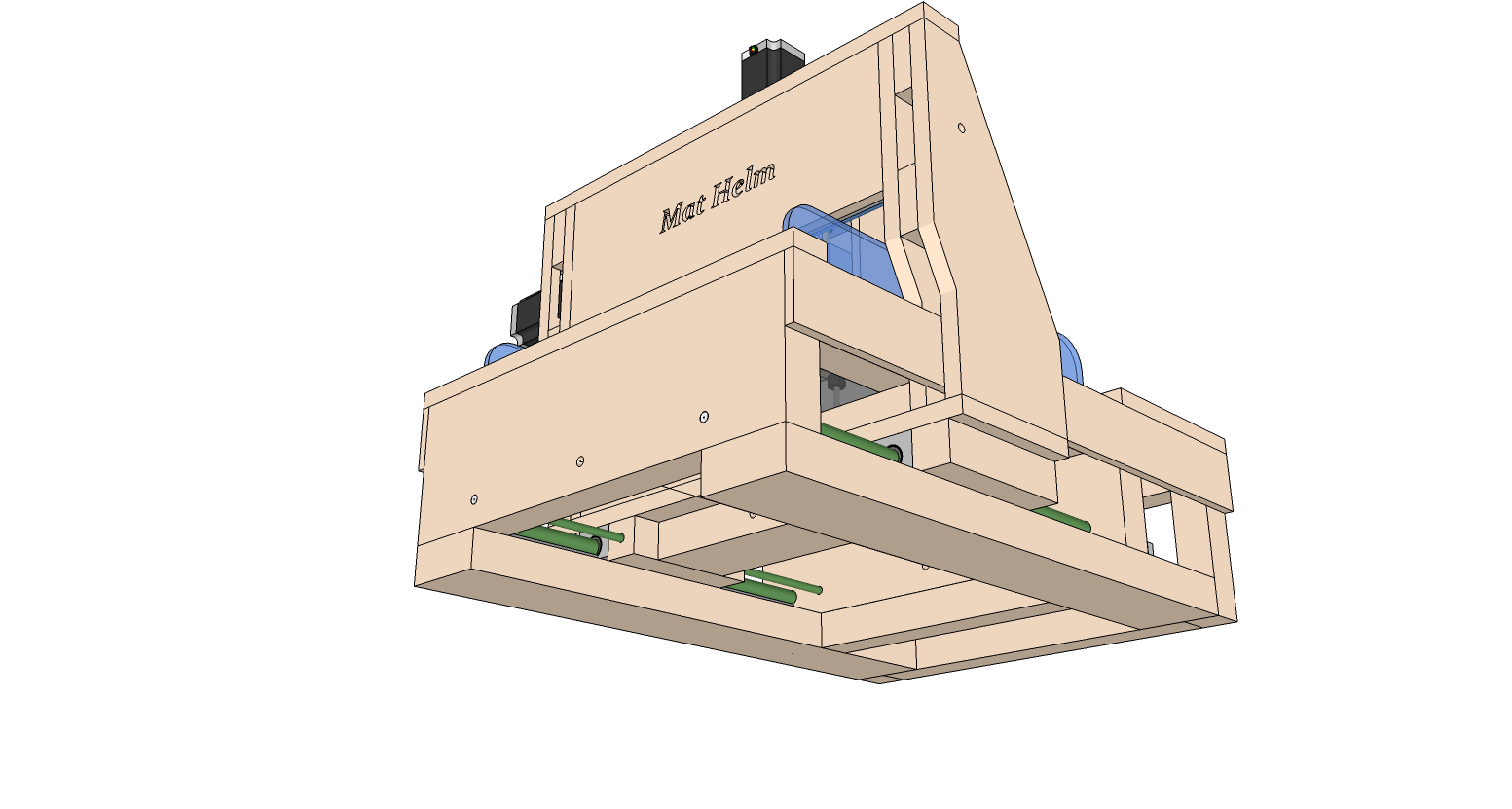
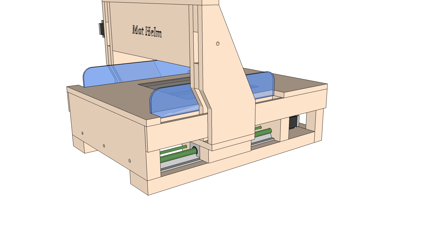
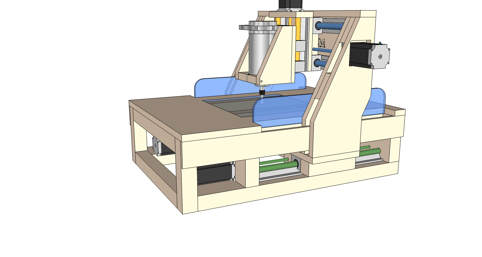
With that small a work envelope I’m not sure if the cantilevered moving gantry is the best design they could use. Moving table fixed gantry is better. Fixed gantries are just naturally more rigid than moving ones are. Although moving tables do not scale up well.
@Paul_Frederick I thought about that after I reread the tittle. Brain farts are a common occurrence around me so… ;p
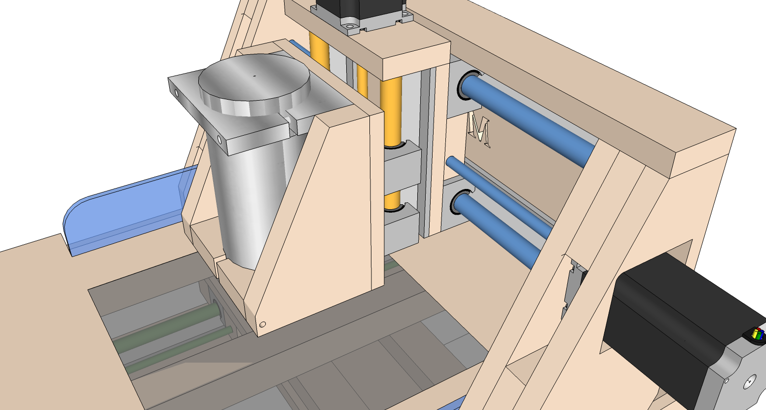
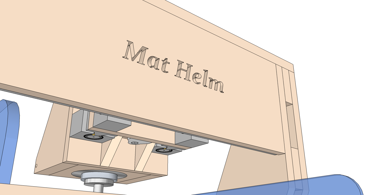
I think the bit/motor/mount height could easily be adjusted to get the full Z axis travel. Assuming what is allowed for in the design is sufficiently rigid.
Yea, I’ve thought about that a bit. Best setups I see are converted mills. Was trying to keep this design a simple build. Like a lot of the ones I see on the net. And being that I wouldn’t actually start building anything until I had parts in hand, I may try and see how simply I could design one with a stationary gantry like you mentioned. Thanks… again…
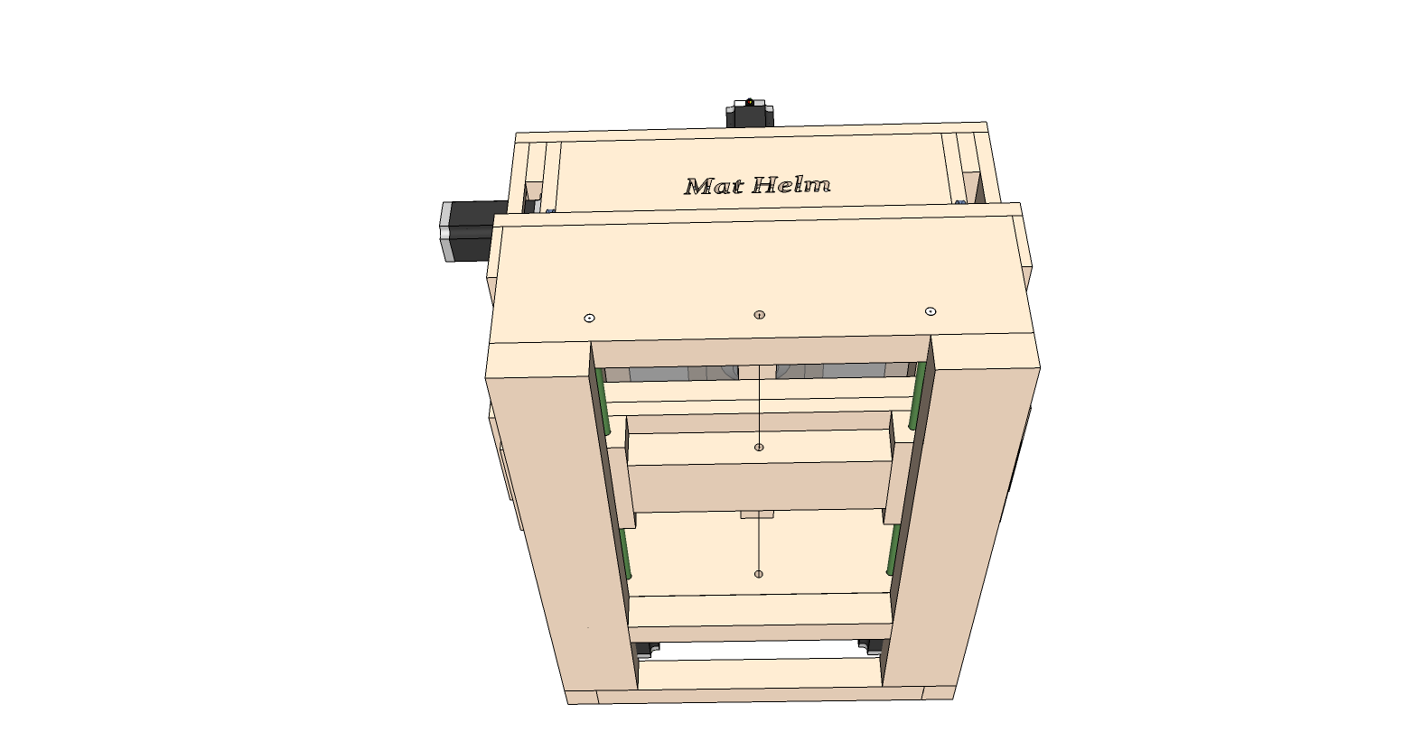
Two X-axis motors seem overkill for such a small machine.
If you want to do PCBs, figure out what size blanks you will be using, A4 (210x297 mm) is popular on this side of the pond.
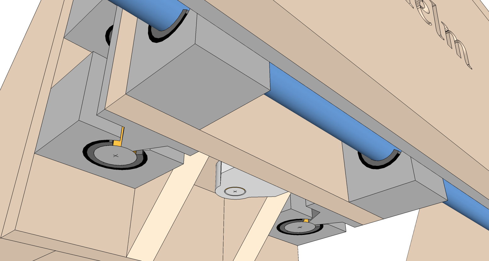
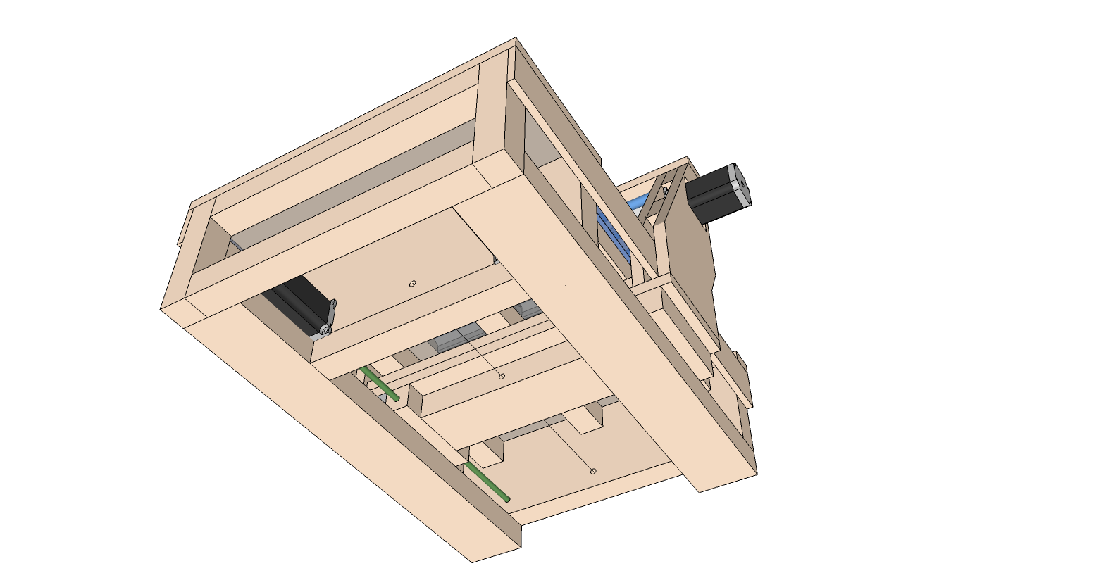
If you could “wrap around” the X and Y axis motors it would make the machine more compact. However with stepper-motors you don’t want a reducing gear/belt drive - maybe 1:1 belt-drive would work. You could then have the Y-motor on top of the Y-beam and the X-motor under the work-area.
@Paul_Frederick great video! I’ve got a screenprint-unit here. So making good films and exposure times for uv-light shouldn’t be a problem. But first I have to learn Eagle better (esp. exporting the boards to film and gcode for drilling). I think you’re right - learning to etch is the better way and the mill only for the drill/cutout job…