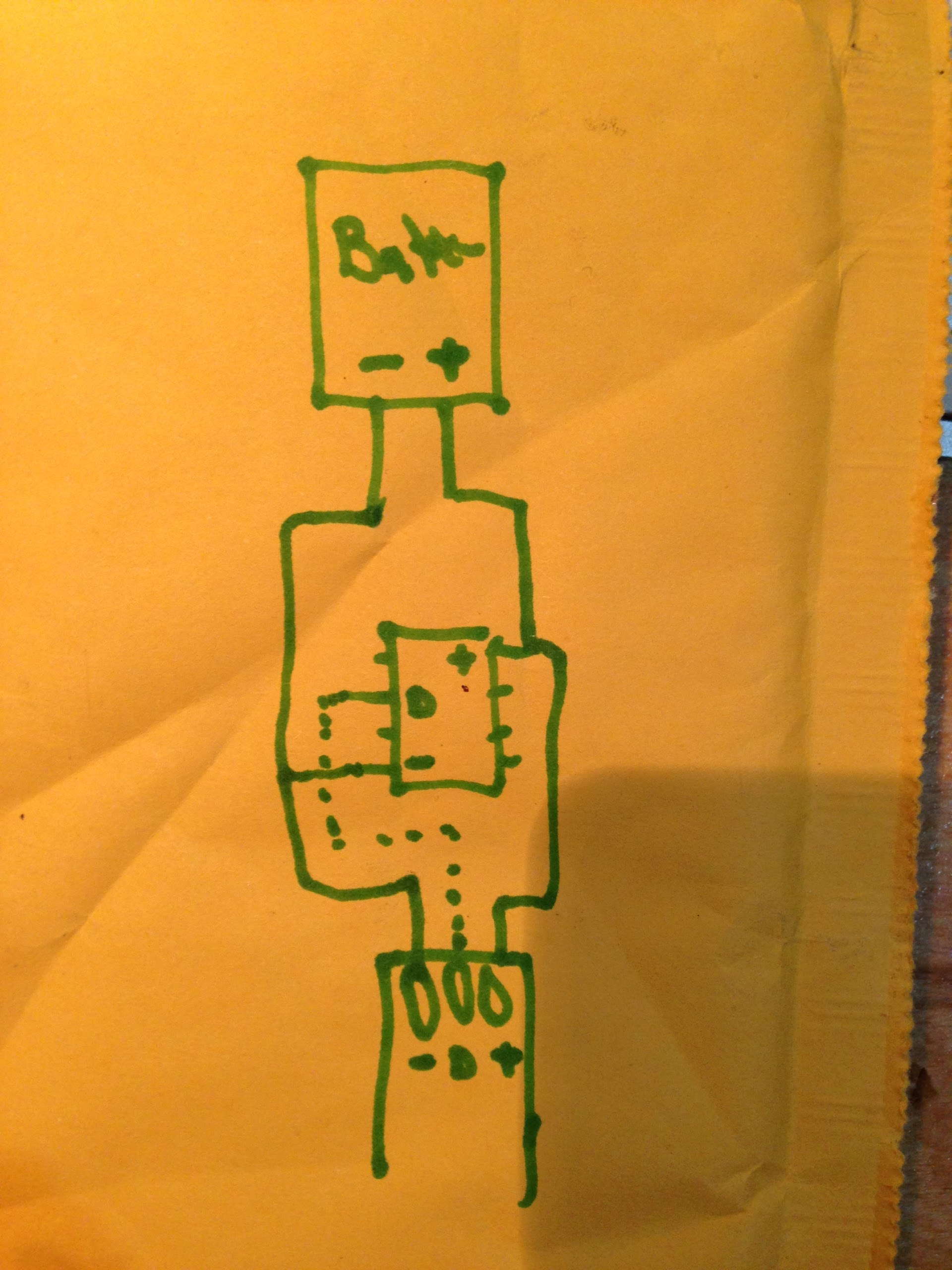
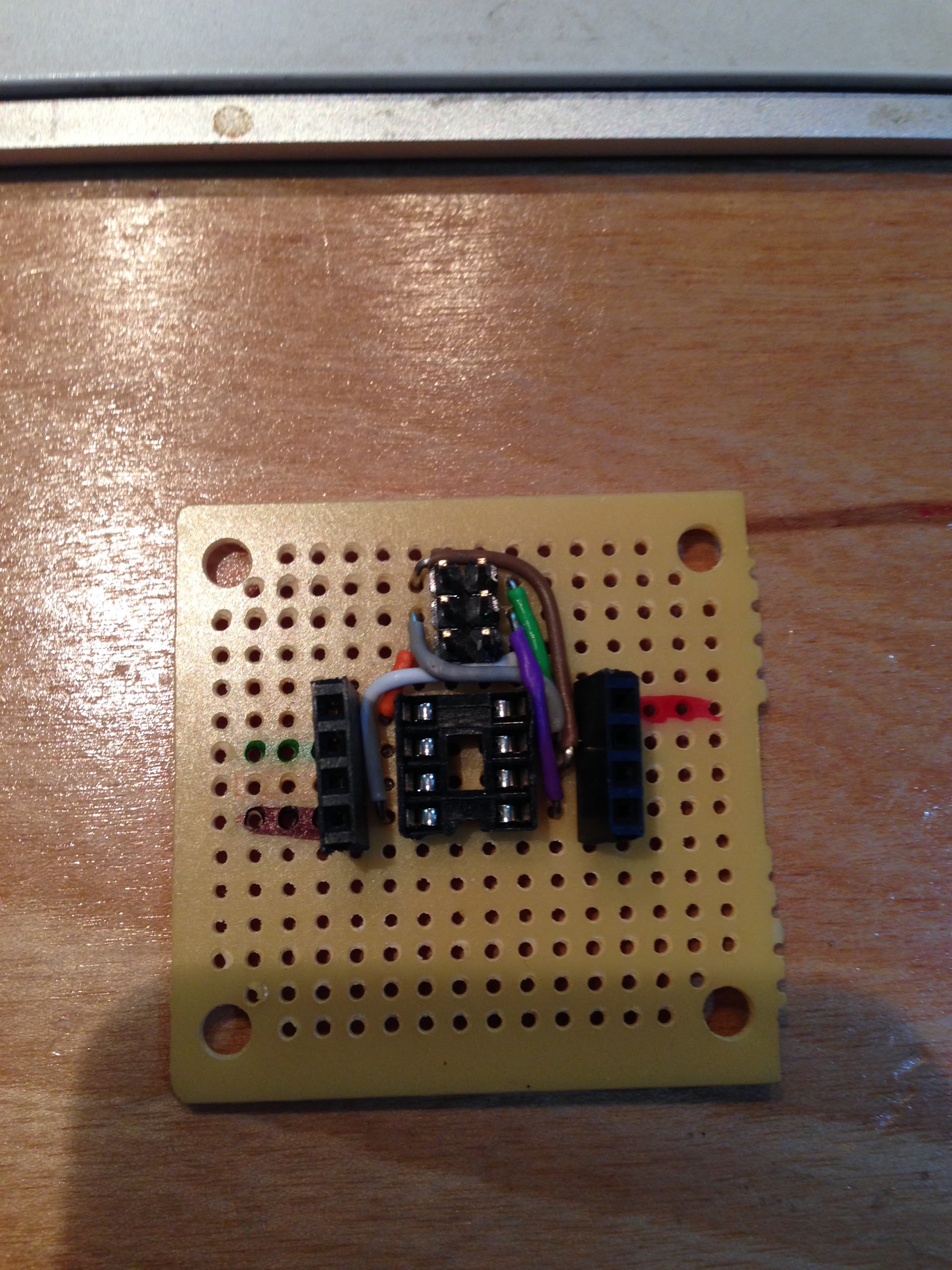
LOL. Just for grins, I created a layout with an SOIC package of the tiny85, one decoupling capacitor, one pull-up resistor on the reset line, 4 header pins output (so it can be used with clock-based strips) and the SPI header as pads along the edge of the PCB. 20mm x 10mm. That’s still thinner than most LED strips. I think the thinnest I found was 11mm. I can probably shrink it even more along the long edge but there comes a point where it’s just not worth having something that small made into a PCB anymore.
I saw the Blinky tape, did not see how they made it. As for a button, anything’s possible. I’ll research button styles and where to stick one. I’d like to stay on the same side, but maybe moving certain things to the bottom wouldn’t be so bad.
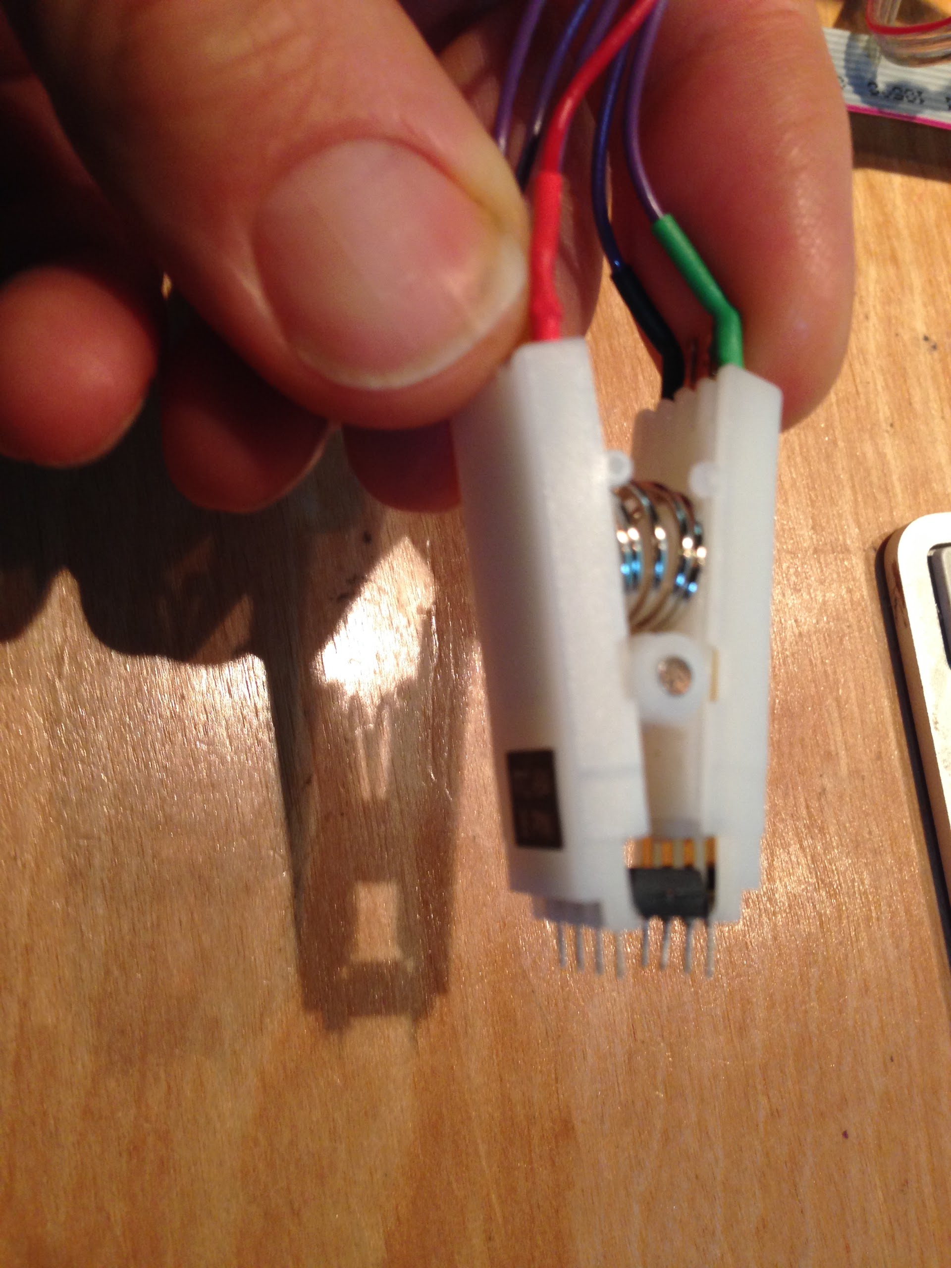
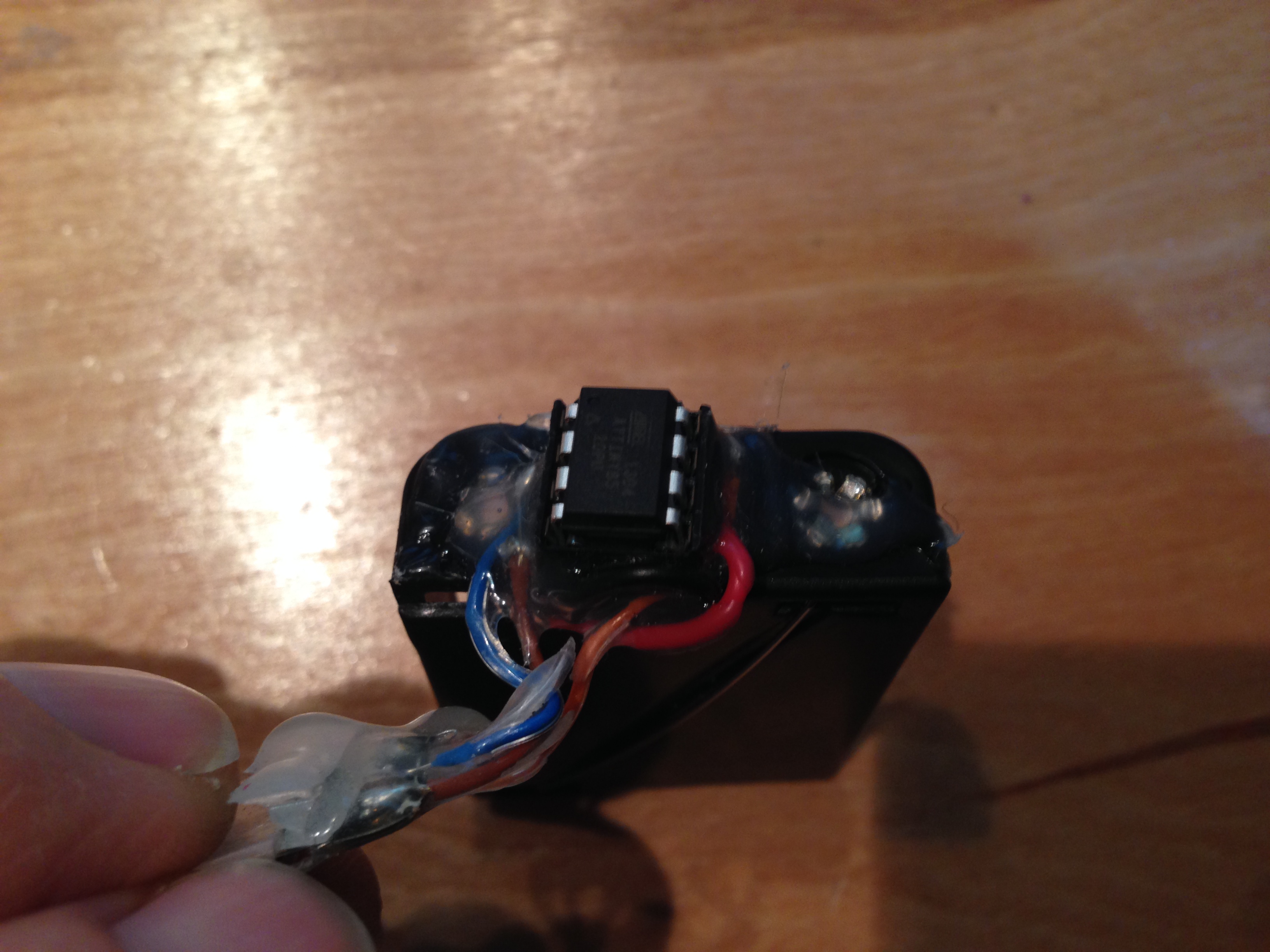
Looking at the pictures for the BlinkyTape, it just looks like a small PCB attached at the end of the string. It doesn’t appear to be part of the tape itself. So that would essentially be the same thing I did, create a tiny PCB that you could attach to the end of a strip.
That is exactly how it looks to me, too, and I’ve got one here I’m looking at. Plus, they extended the silicone over the little PCB too; it’s a great little package.
I really like the idea of a little board that can glom directly onto the end of an LED strip. ATtiny is good for size and cost, but I still tend toward the ATmegas; I like one-cycle MULtiplies and having 2K of RAM. But that’s just me.
@Tod_Kurt I really want something dim, as in low power and not very bright. The LEDs out there are way too bright and power hungry for wearables or bikes or whatever. Yes, you can dim the bright ones, but that really means throwing away useful bits and most of the dynamic range.
That would be for a project for next year when I will have developed the software skills to make it look good. Maybe by then I’ll find that the issue really doesn’t matter; I’ll just dim them. If I do end up wanting these LEDs, I expect that I will have to build them myself. I can’t imagine there’s much call for dim LEDs. Dim would not be a great marketing point. More skills to develop if I have to build them.
You’re not throwing anything away by lowering the current to the LEDs. In fact, you are saving on battery usage. An LED that runs for four hours at 20mA, will run for eight hours at 10mA. As for the range of color, well yes, there is only so much you can do with a specific amount of available light.
@Paul_Russo : what kind of ‘runtime’ did you want to achieve, for how many LEDs, and what kind of battery pack were you thinking of? I’m curious what sort of applications folks have in mind, especially for battery-powered projects.
@Paul_Russo Yeah I really wish the WS2812 LEDs had better power management and higher bit-depth. And they draw noticeable current even when dark. The next-gen BlinkM I’m tinkering with has a FET to switch off Vcc to the LEDs to save power.
The WS2801s are interesting. Although the chip is capable of constant current that is adjustable, that mode requires three more resistors, so all the implementations that I know of are set to constant voltage. Even if you swapped out a smaller lower current LED, the chip would still try to send out the same current. To make a low power LED with that chip, you would have to make a circuit that has those extra three resistors as well as one of those tiny tiny (expensive) low power RGB LEDs.
The current for the WS2811 chip does not seem to be adjustable.
So build a circuit with three digital potentiometers. You can then control them from the controller and set whatever current you wish to use. Or would that be too much?
You’re not throwing anything away by lowering the current
to the LEDs. In fact, you are saving on battery usage.
You are right that you’re saving on battery usage at 1/8th brightness. But you are throwing away 7/8ths of your dynamic range. That turns your 8 bit LED (0…256) into a 5 bit LED (0…31). You don’t see this from the high level code but at the hardware level this is what happens. This is a hardware limitation, not the fault of FastLED.
Here is some demo code. At high brightness the 256 steps are smooth. At low brightness the 32 steps are noticeable. It’s the same code twice, just different brightness settings.
e class="onebox githubgist" data-onebox-src="https://gist.github.com/mtnocean/8590389">
gist.github.com
// How dimming in software reduces the bit depth.
// Dimming reduces the brightness level from (0..255) to (0..31)
// eight bits per color to five bits.
// Notice how the LED flickers the second time,
// especially at the lowest brightness levels.
// This is a hardware limitation, not the fault of FastLED.

#include "FastLED.h"
#define NUM_LEDS 1
#define DATA_PIN 13
There might be a way around this, but the margin is too small to contain the code here. (Short version: temporal dithering, which works great under a fairly strict set of conditions.)
But basically, you’re right: if you set Brightness to 32, you have 32 levels of brightness.