Getting the board programmed and moving the motor with it.
I have built the board, have all the components wired in, and loaded the Lua code from robot-actuator-esp32-v8-master. I loaded the code through ChiliPepper Work space.
Questions:
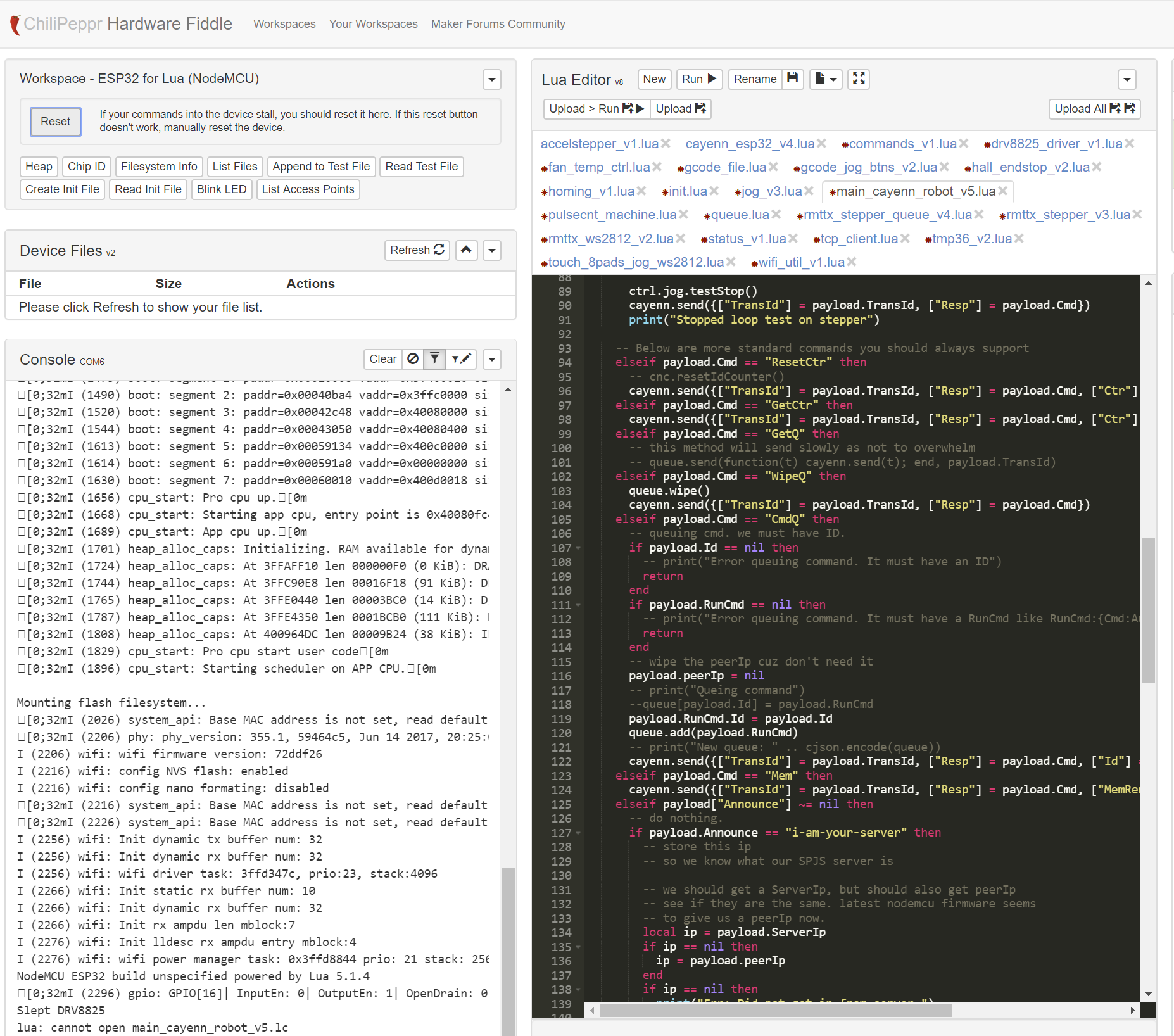
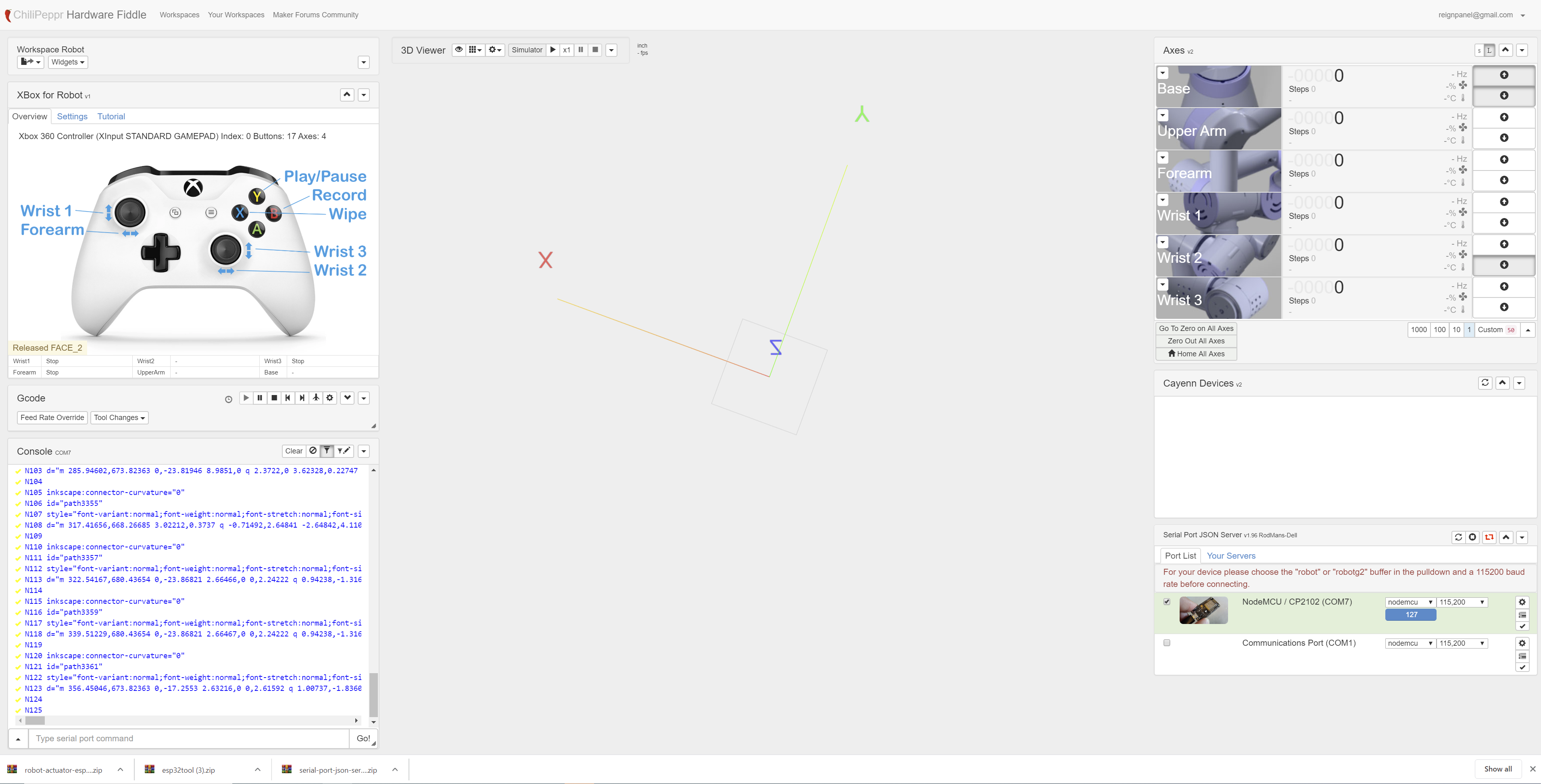
Is the "cannot open main_cayenn_robot_v5.1 a problem? Screen shot
When I go to the Chilipepper workspace, it says I should choose robot in the json drop down, my json drop down does not have robot or robot2?
I saw from Johns video that he knew he was operational with his board when the WS2812 (white led lit up) Mine does not light up, when should I expect that?
The ESP is lit up and the 5V power led is lit up.
Thank you
Wow. You got really far. Yeah, are you sure you uploaded all of those Lua files to the ESP32? They seem to have red asterisks meaning you didn’t hit save on them (if you modified them, which i doubt you needed to). That Upload All button can be your friend. Then you should hit Refresh on Device Files to see all your files on the ESP32. Post lots of screenshots as they massively help us/me figure out what’s going on.
Thank you John for taking the time, I am determined to get this working.
I plugged in a new esp 32 and started the process from scratch.
Step 1 install the esptool.pay and the the files in that folder. That went fine it looks like.
Step 2 install the lua code through ChiliPepeper
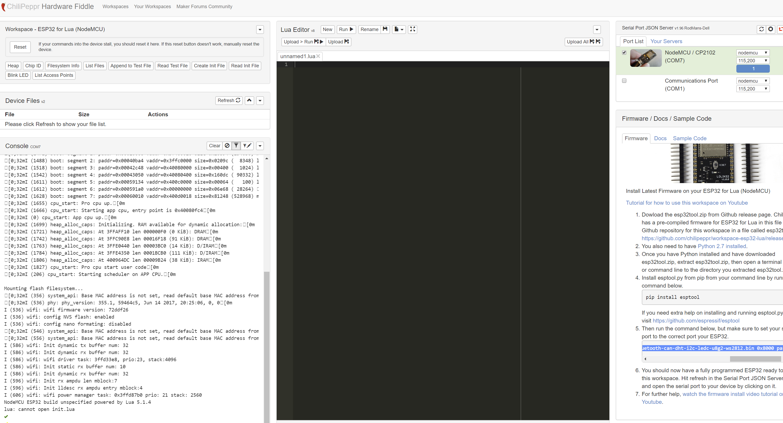
2a. Connecting to the board through Json in ChilliPeper, before loading any lua code, screen shot below.
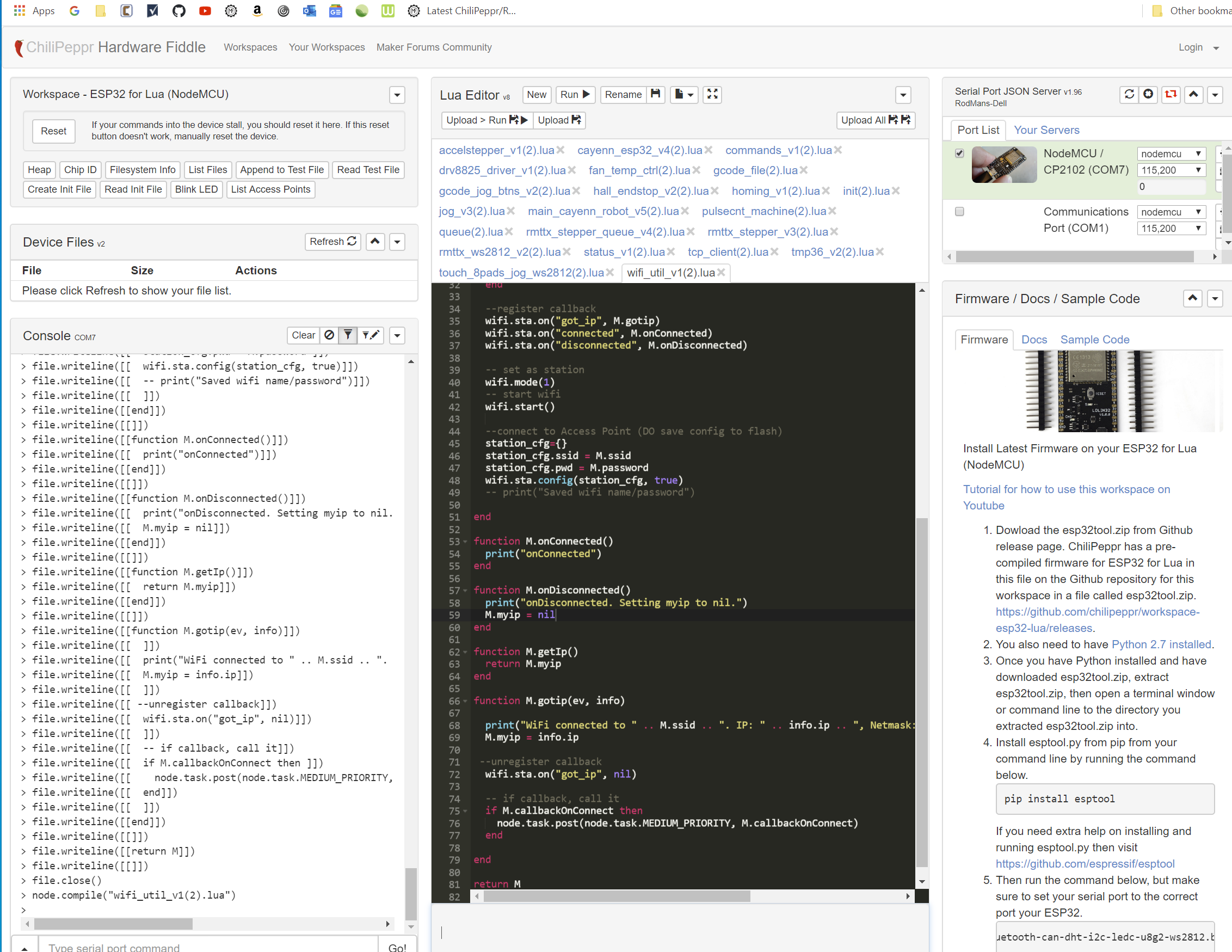
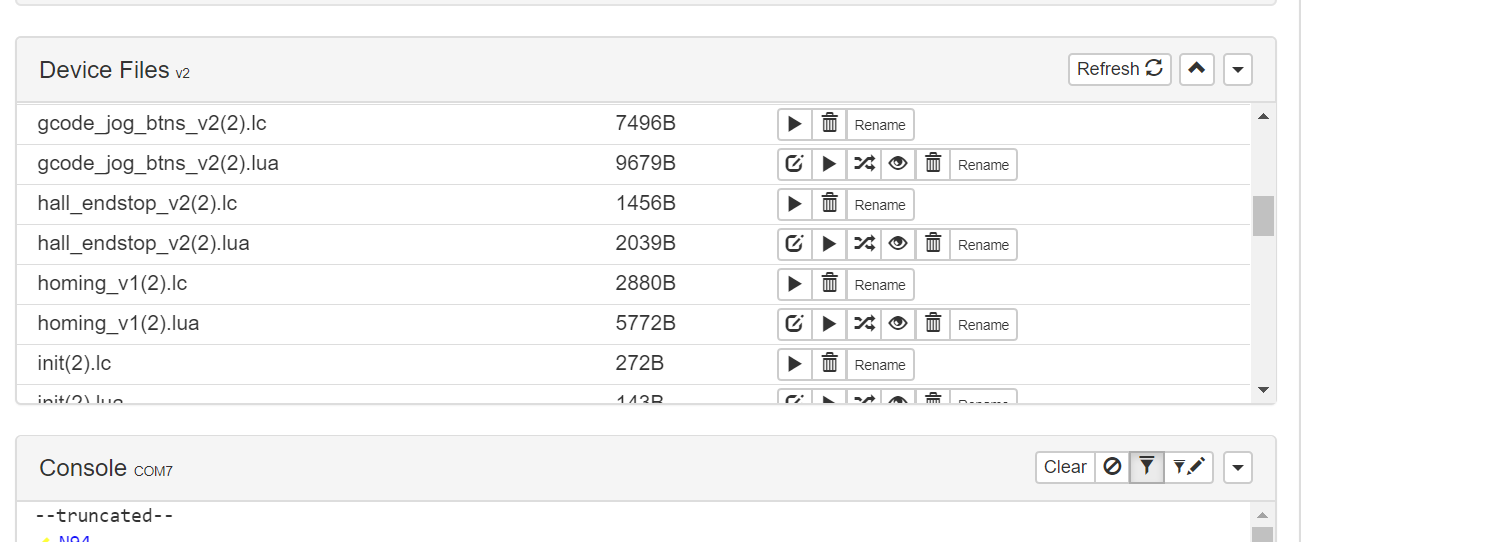
2b. Upload the Lua code, it looks like it all uploaded fine this time. I made sure the scrips were all new by renaming them with (2) at the end.
I did hit the run action for each device file just to see what happens. There were some that did not execute, I do not know if that is a problem?
Step 3? Use the Chilipepper Robot Workspace
There is no robot or robot 2 in the Json drop down,
I did get the controller connected.
Not sure at this point where to begin or to know if I have any issues?
The White LED is still not on.
Hmm, you might want to do a tutorial on how to create Lua modules to help understand how all of the code works together. Renaming the files breaks everything as they all have a “require” line at the start of each file that tells Lua what sub-files to load. By renaming you broke all those “require” lines.
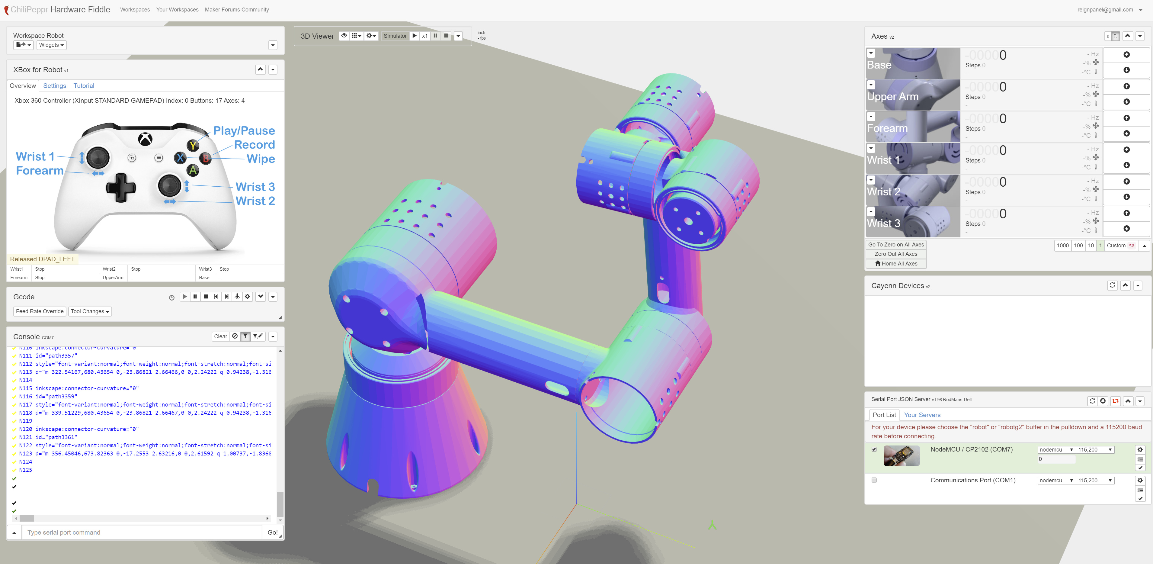
Once you have all the code uploaded, you should get the correct ws2812 led light but also be able to use the touch controller to jog the device around. The actuator should also auto-show up in the Cayenne window if you configured your Wifi settings correctly in the Lua code.
Oh what a nube move on the renaming. Long NMN story on that.
I got the correctly named file uploaded.
Ahhha…You say if I configured wifi correctly in lua code. I suppose that means ip and password? I need to do that.
If you look through the Lua code, you’ll start to understand the hierarchy of all the files. I also, always, put my configurations at the top of each file to make it easy to change configs. I think the wifi network name and password is in the main file, or i left it in the wifi lua file at the top. Can’t recall.
Also, i’d love some photos of your physical circuit board or actuator just for the rest of us to see somebody else making progress as this project does have a lot of intricate pieces.
I will have to do some studying, yes.!
I am not sure what the “main file” is?
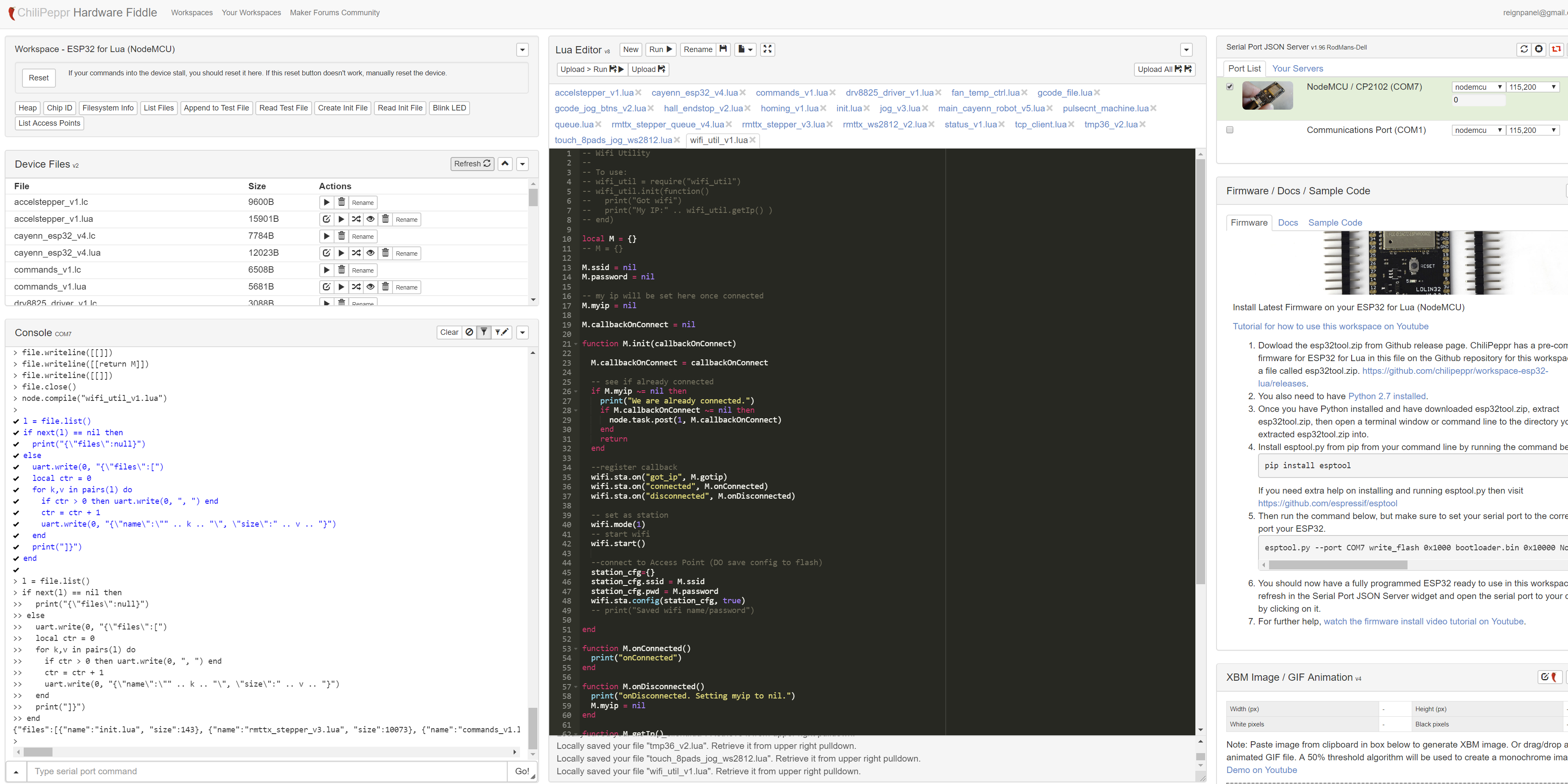
I uploaded the sample esp32wifi code, its scrolled past my password and SSID on the edidtor screen shot. I ran it
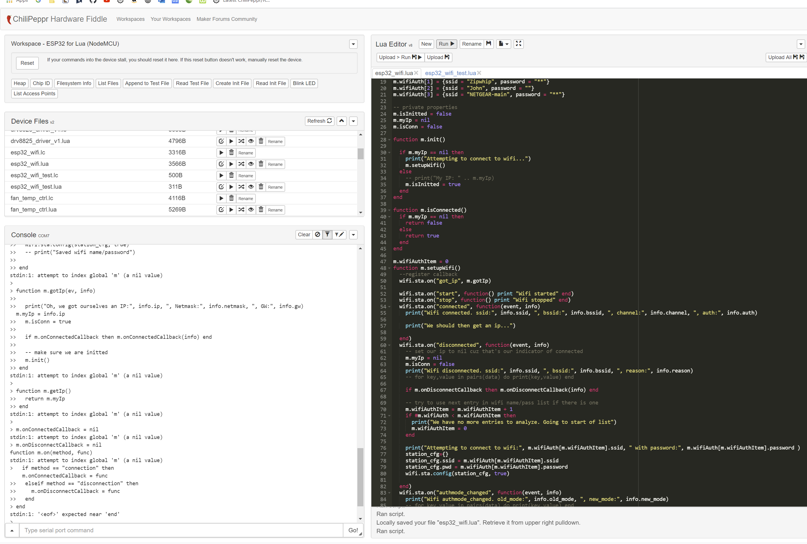
I uploaded the sample test WIFI and Ran it
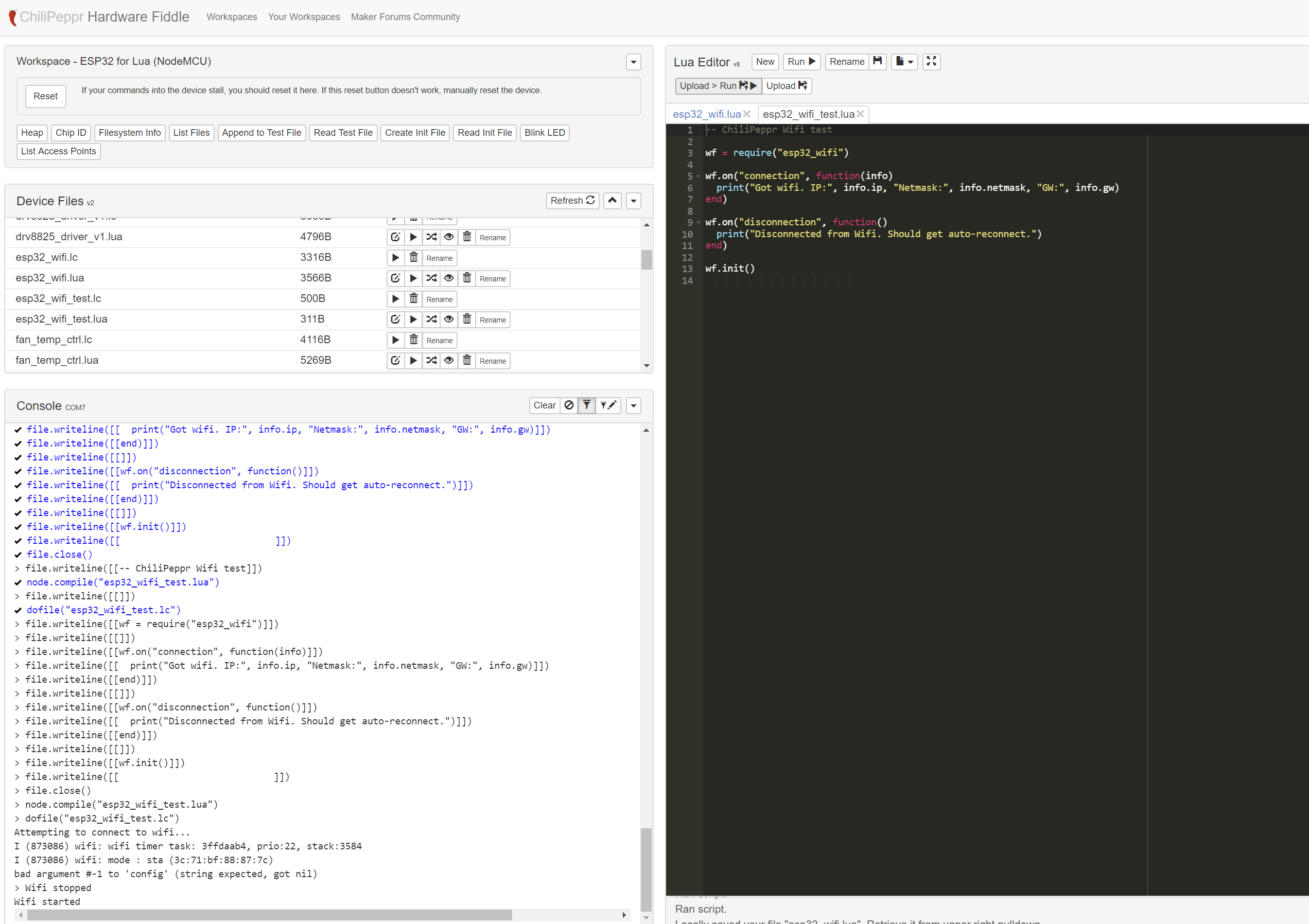
I edited the wifi_utility code to have my SSID and Password, it is scrolled past that on the editor, I ran it.
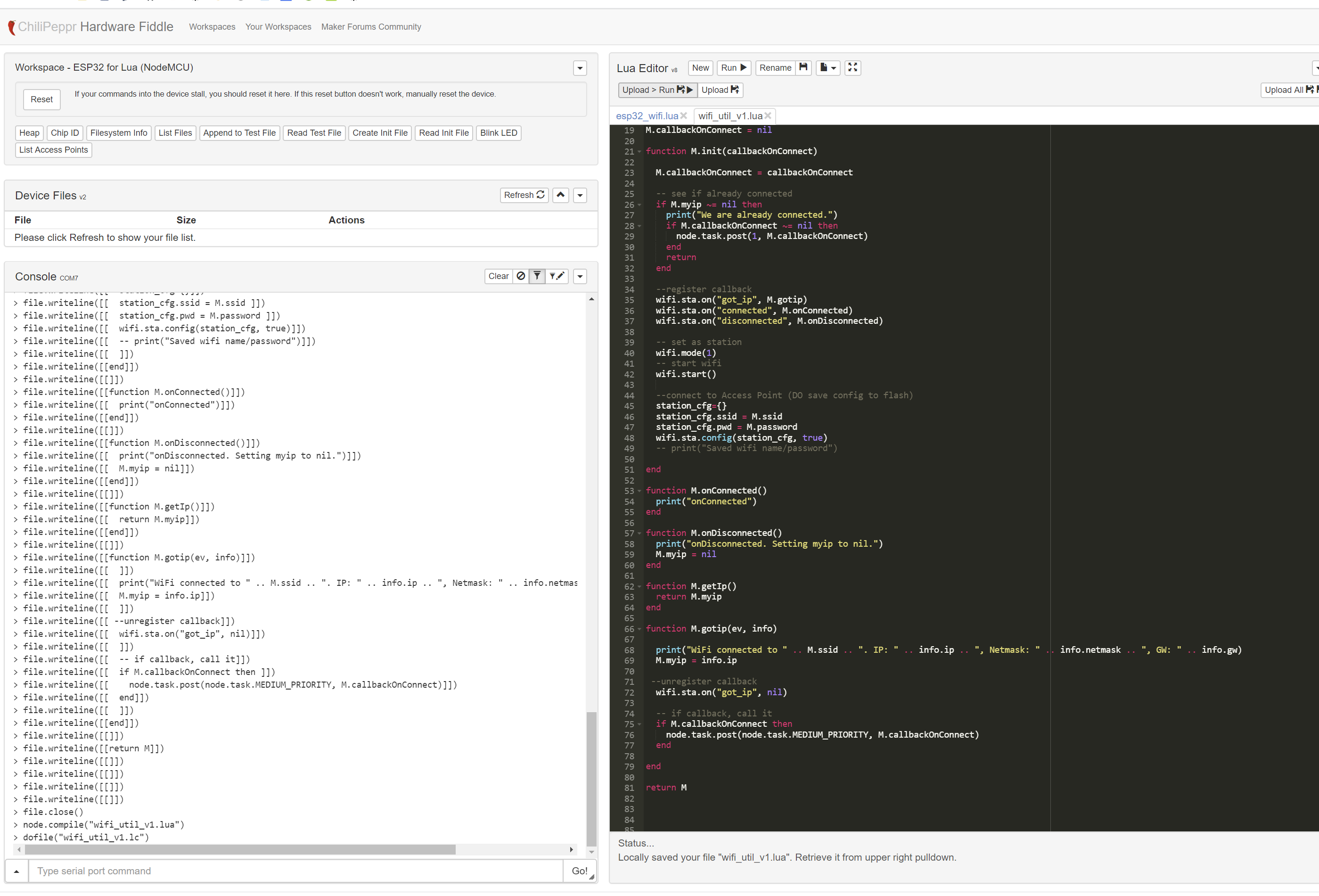
It still does not show up on the Cayenn devices… guess I am stuck here!
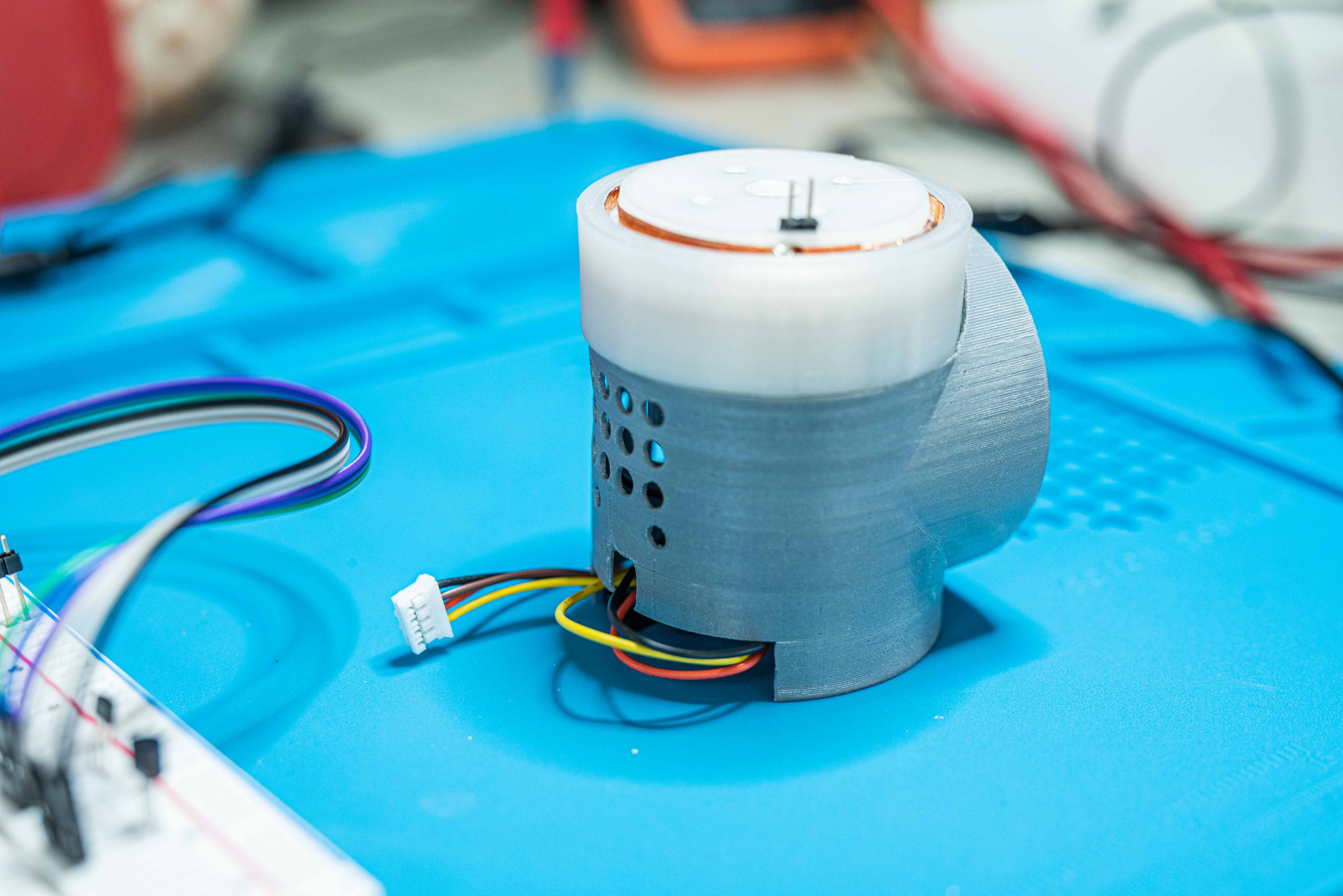
Here are some photos and advice.
This is about my 5th actuator circle, 3rd un-smoked esp 32. Recommend if you have not soldered surface mount before or not for a long time, do some practice and get extra actuator circles. Also, don’t forget to set your step down power supply to 5V. I don’t know what its set to out of the box but I did smoke 1 esp 32 with it and the other by miss-wiring. I tried right out the gate to get the PCB set up wired into the wrist shell before testing… don’t do that! Bench test the board with motor, fan, temp and hall effect jumpered. Getting the pcb to fit into the wrist shell is a job in its own and requires custom jumper wires. You should know it all works before stuffing it into the shell.
Fusion has two files you can follow to build the board, the “Actuator Circle” file actually has some extraneous male pins shown for the DRV, if you solder them on you will wind up replacing them with female when you go to plug DRV. The actuator circle in the “BotBot” file is has it correct. There are a few other things that the BotBot File shows better, I recommend using it to review the components.


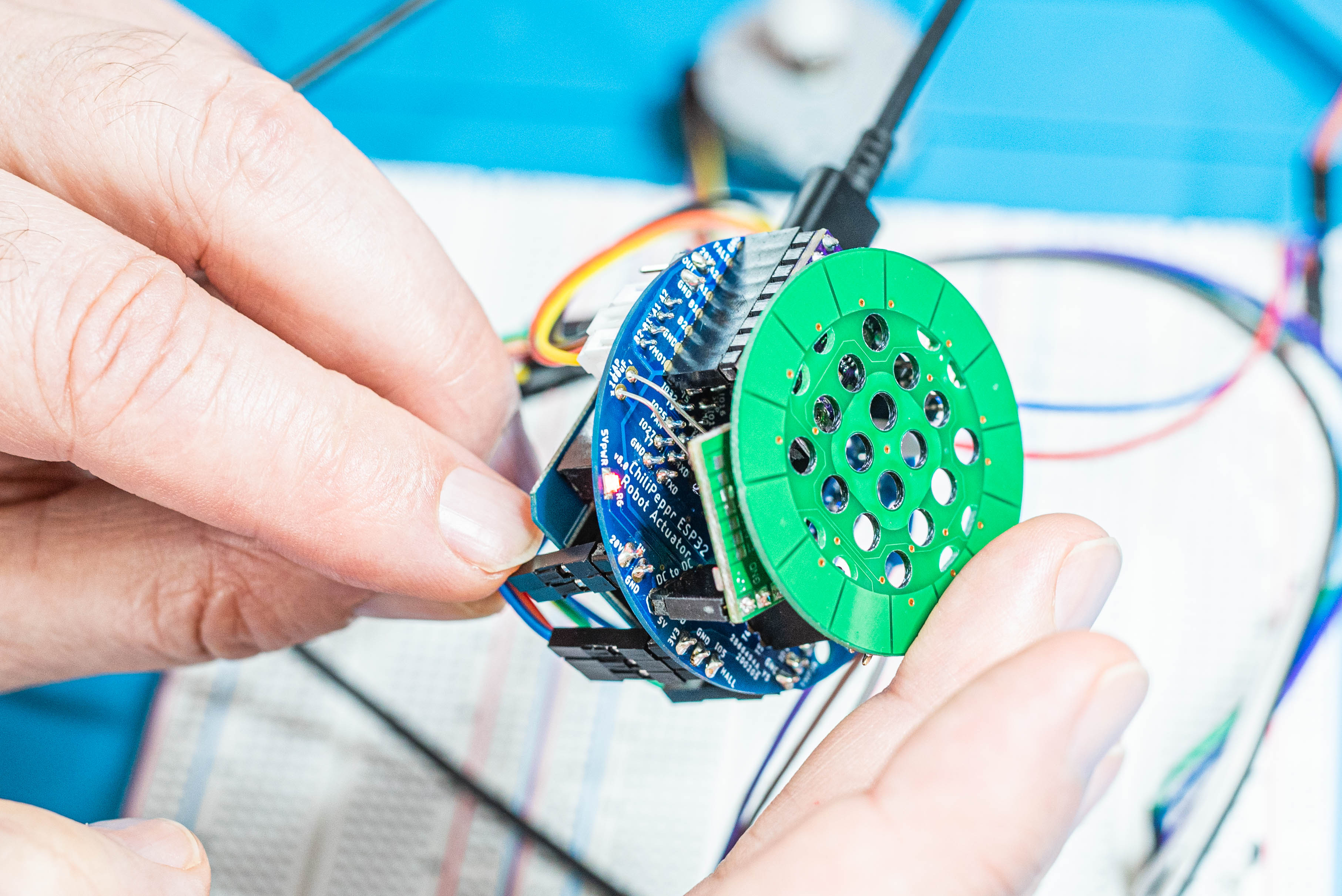
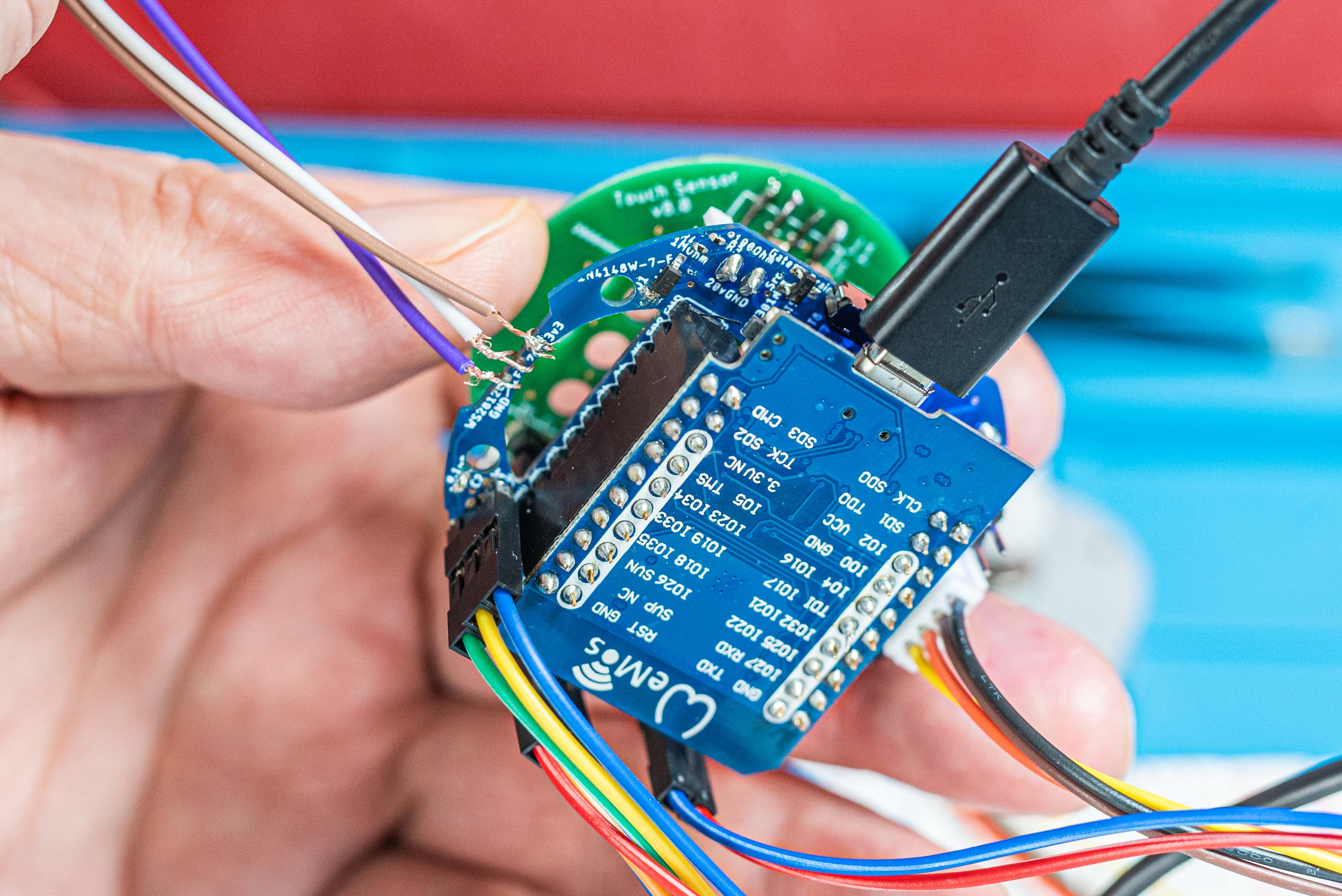

The White LED is wired in by the jumpers in the photos because I had been breaking it off accidentally in my subsequent test boards, it really should be soldered directly to the board. The other jumpers go to the Hall effect and temp sensors. I don’t have the fan plugged in in the photo.
The actuator took about 3 attempts to get, I finally settled with nylon and 100% gears. I did its pre-testing with a simple Arduino circuit. I used PVA supports between the flex part and the base of the ring, I guess you don’t have to do that.
FYI: I found that a portable foot spa with bubbles and heat is really good at resolving PVA.
Wow, you’ve gotten so far. You are basically to where I’ve gotten. Nice work!!!
Ok, init.lua is the file that the ESP32 NodeMCU firmware runs on boot of the ESP32. So that’s always your entry point. You notice it says:
– Put DRV8825 to heavy sleep
gpio.config({gpio=16, dir=gpio.OUT})
gpio.write(16,0)
print(“Slept DRV8825”)
dofile(“main_cayenn_robot_v5.lc”)
That’s because it’s prudent to ALWAYS put that stepper driver to sleep to not burn out the motor in a hold position. It forces that on each boot even if you are debugging and screw something up. I suggest you just comment out the dofile() line if you are debugging and rebooting a lot.
Then, of course, it’s calling main_cayenn_robot_v5.lc so that’s your real entry file that starts the main codebase. Then just work your way down the hierarchy of files from there.
It seems to be in your screenshots you’re trying to start from other files, which won’t work. I did design the code in such a way that you could start a file on it’s own to test it, but that’s inconsistent, so best to start from the main entry point.
I just looked for you. It’s line 8 thru 10 you have to edit to setup your wifi settings in robot-actuator-esp32-v8/lua/ main_cayenn_robot_v5.lua
– **** User Defined Variables **********
cayenn.ssid = “NETGEAR-main”
cayenn.password = “****”
BTW, you are using the repo at:
right?
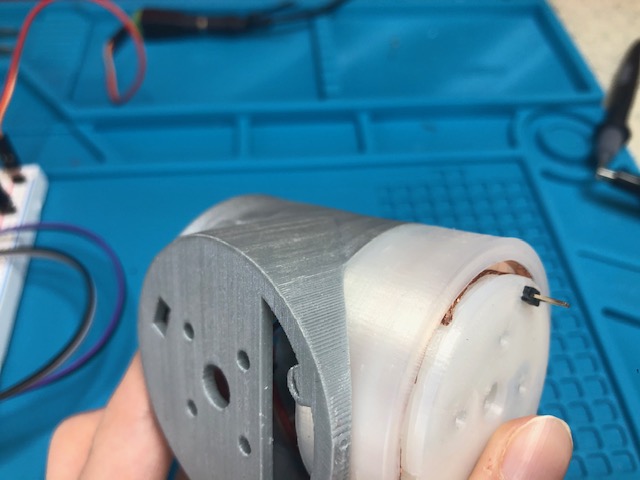
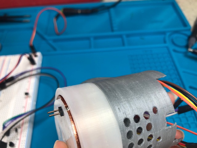
BTW, that shell looks too small for that actuator. It doesn’t seem right in the photo. They should be identical diameters. I don’t recall any major change in shell diameter such that it would have been a file version, although then again maybe, but is it just an optical illusion in the image that the shell is so much narrower than the actuator? or is it that just you don’t have it screwed down so it’s just off center?

Thank you John!!
I will go back over the process from scratch again with your information. Once I get past this cayenn device problem I will be home free I think it is my last stumbling block. I plan to make an awesome robot!!
You have a good eye, I had some fit up problems and had to torque the shell a little to get it screwed down. Once I get the board working I’ll get the shell/actuator perfected. I will probably make the shell a little bigger though in the final version, I had some problems getting all the wires to cram in the first attempt. And you can see I eventually broke the bottom of the shell on one of my attempts to pull the board back once I had it wedged in.
Yes I am using that repository.
Ok, in that photo the shell looks fine. Maybe it’s just the white actuator vs the grey shell color. Yeah, I had a very hard time fitting all the wires in. That’s why I ended up using very soft silicone wires and really small ones for the TMP36 and the wire connectors. I believe i put a link to the aliexpress 4pin silicone wires.
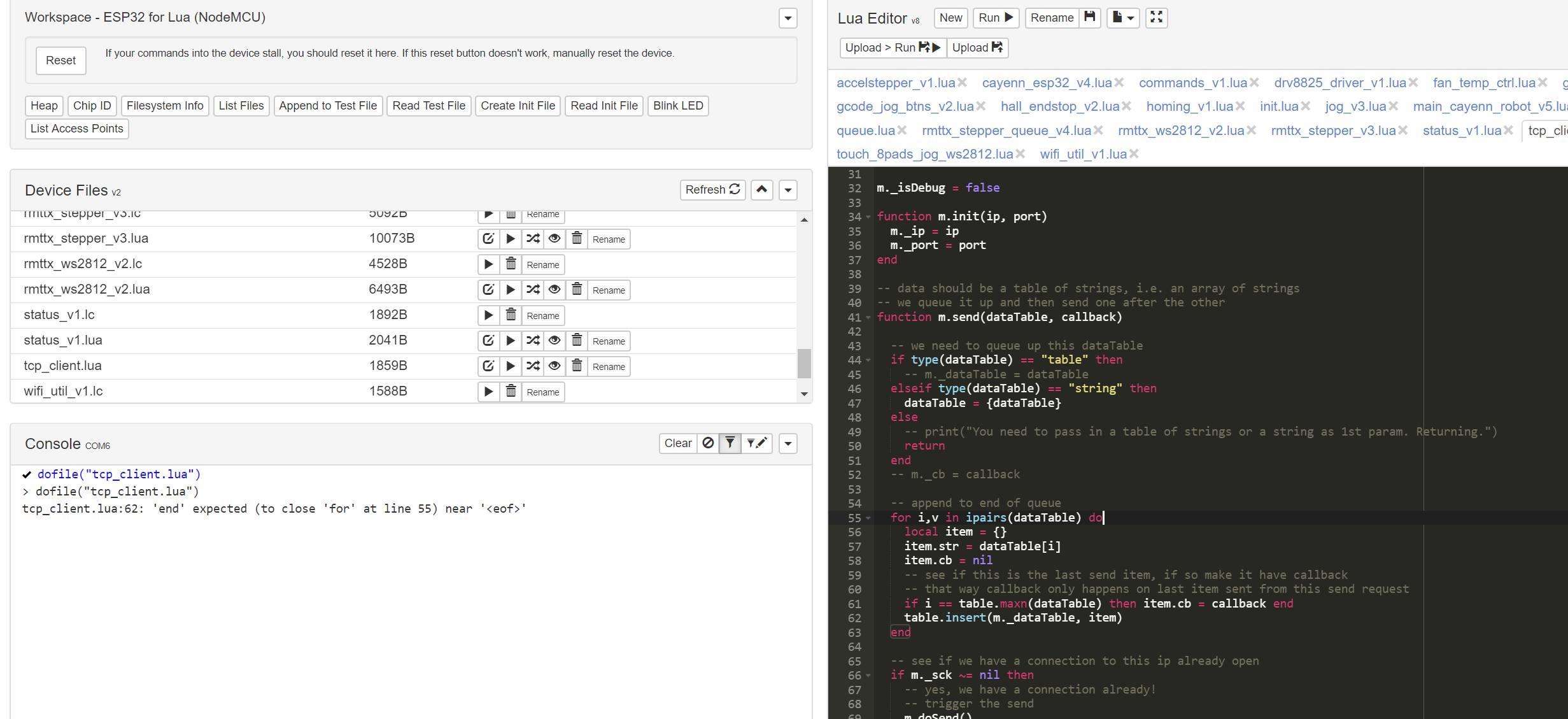
Sometimes I find that when uploading the files, especially lots of them in a row, the lines can get corrupted. So my guess is just re-upload it and see. Or dump out the contents of the file from the ESP32 and compare to the original file to see what went wrong. From that screenshot that code on the right looks correct.
That actually fixed that issue for now.
Do I understand this correctly, once the lua code is installed from the esp32 work space, I then should click the run button on file init.lua to get the program to activate? And then go to the robot workspace and it should show up in cayenn devices in the arm workspace?
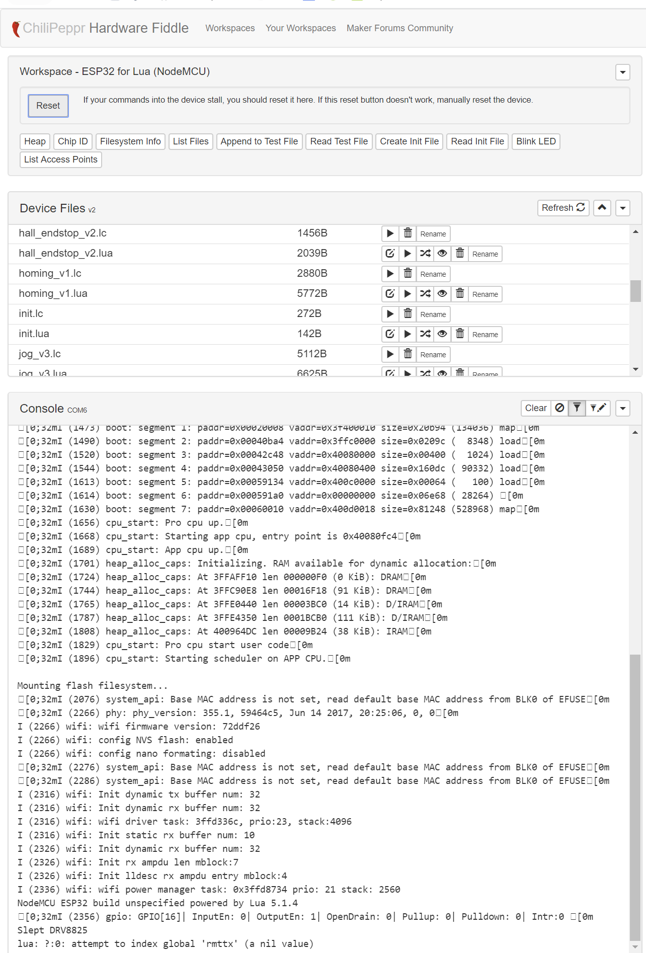
This is what I get when hit the rest button in esp32 workspace:
This is after I hit the run button in device files for init.lua:

After hitting the gcode jog btns v2 run:

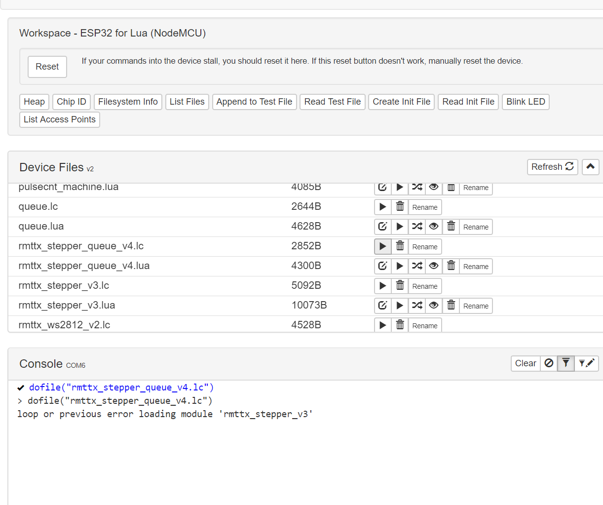
After hitting the rmttx stepper queue run:
After hitting the rmttx stepper v3 run
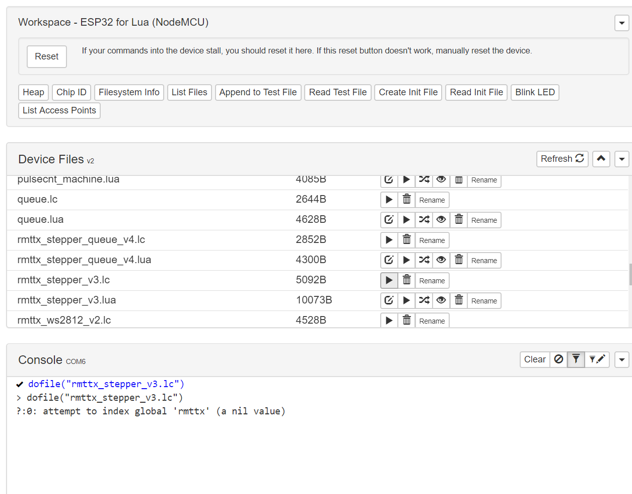
is the attempt to indext global “rmttx” (a nil value") a problem?
Yes, the “is the attempt to indext global “rmttx” (a nil value”) a problem?" is the problem. You are not running the firmware I included in that repo. Or, you are, and I screwed up the latest version of that firmware. Did you upload the firmware I included in that Github repo? It has the rmttx C module I wrote that is an add-on to the NodeMCU base firmware. It let’s the stepper motor steps be queued up in the RMT hardware for smooth step delivery with acceleration/deceleration to the stepper motor.
Oh my G, I had been loading the esp/32 firmware from the workspace link instead of loading the firmware from the repo. Your instructions were quite clear, sorry I have been wasting a lot of your time.
Starting a redo now…
To be clear, the firmware repo looks like this
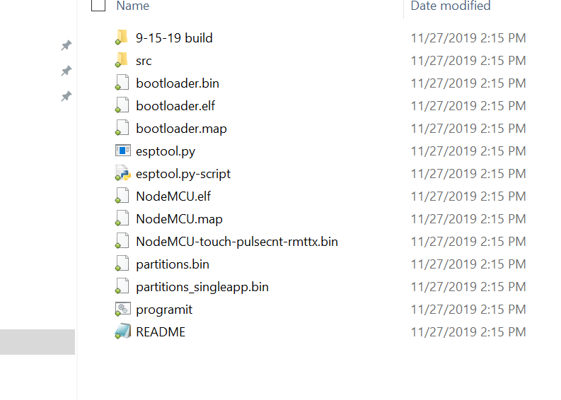
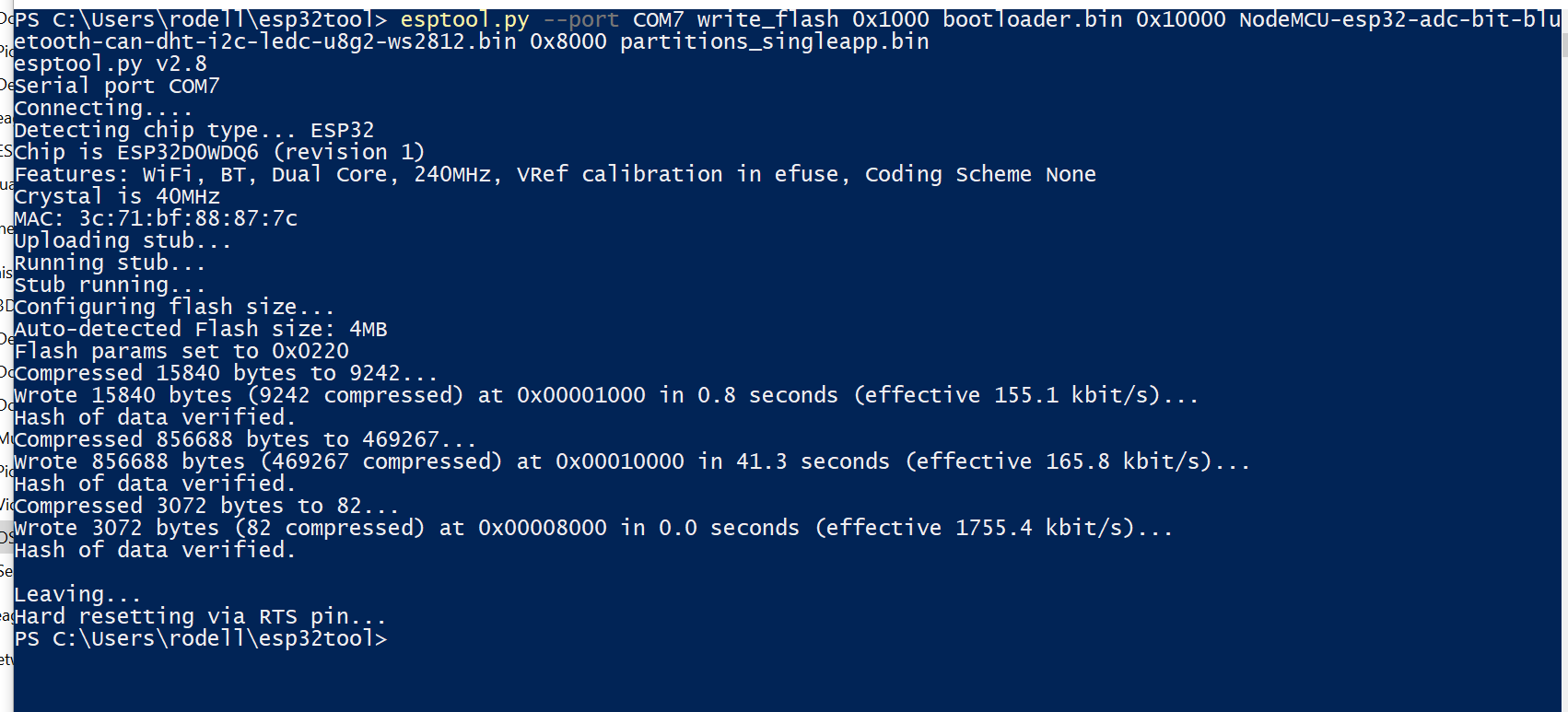
I am running the command
esptool.py.exe --port COM6 write_flash 0x1000 bootloader.bin 0x10000 NodeMCU-touch-pulsecnt-rmttx.bin 0x8000 partitions.bin
From the directory it looks like this
PS C:\Users\rodell\Downloads\robot-actuator-esp32-v8-master\robot-actuator-esp32-v8-master\firmware> esptool.py.exe --port COM6 write_flash 0x1000 bootloader.bin 0x10000 NodeMCU-touch-pulsecnt-rmttx.bin 0x8000 partitions.bin
That is all I am doing for the firmware.
There is a file buried in the SCR folder under modules called rmttx.c, I assume that is being picked up in the firmware update above?
You got it. That looks correct.