Parametric speed handle for machinist vise

TL;DR: thingiverse gitlab; depends on threadlib, which comes with installation instructions for several prerequisite packages.

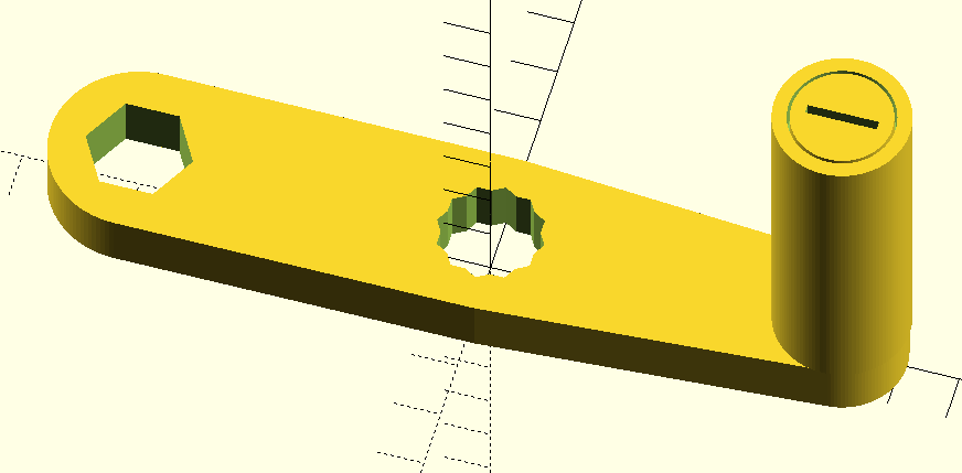
The machinist vise on the mill is a beautiful thing, but when I need to change a setup it takes forever to move the jaw by spinning the hex in my hand, and of course putting the handle on would be even slower. The solution is a speed handle, but they are ridiculously expensive. And it happens that I need 5/8" not 3/4" and I don’t want the three-armed version I found.

I found a version on thingiverse, but it’s for 3/4" hex drive, and it was modeled in solidworks. I want a parametric design to not only support 5/8" hex, but also able to support whatever size you need, preferably modeled in OpenSCAD. I couldn’t find it anywhere.

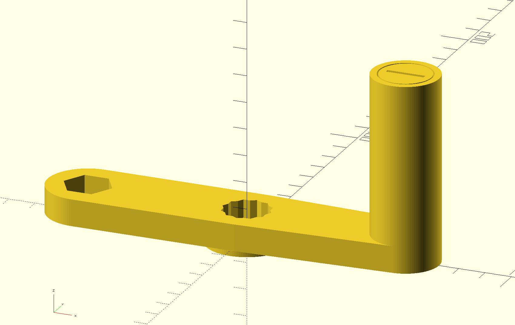
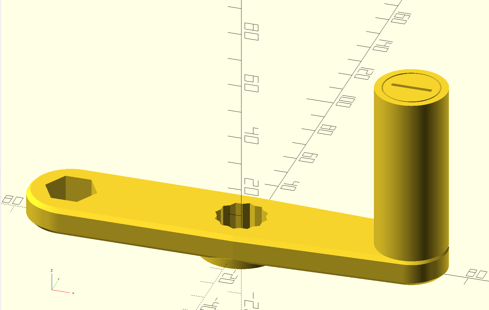
So I modeled it. It allows you to choose the size socket, whether to use a six-point or twelve-point socket, the length between sockets, what thread spec to use for attaching the handle to the crank, how much plastic to put around the sockets, how many thread turns used to attach the handle to the crank (and thus how thick the crank is), how long to make the handle, how thick to make the handle, and how much margin to leave between the handle and the shoulder bolt so that the handle spins freely on the shoulder bolt:

socket_size= 5/8 * 25.4; // 5/8" — 0.625 * 25.4 = 15.875
base=60; // lengths between centers of holes (sockets and handle)
margin=6; // thickness of handle outside sockets and handle nut
thread="M10"; // thread spec, M10 is coarse thread M10x1.5
turns=6; // thread turns; thickness will be turns + 1 * pitch of thread
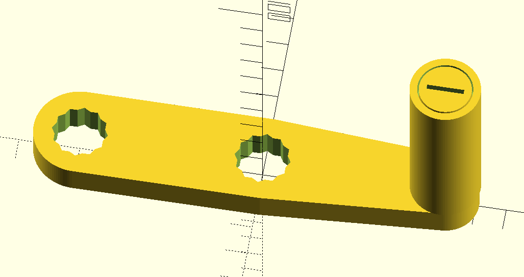
twelve=true; // false for six-point sockets, true for twelve-point sockets
handle_length=70; // total including depth of crank
handle_margin=0.5; // space between bolt and handle
handle_thick=5; // thickness of shell of handle and of bolt head

I put up files on:

  • thingiverse where I may remember to upload substantial changes
  • gitlab where I’ll push every change I make

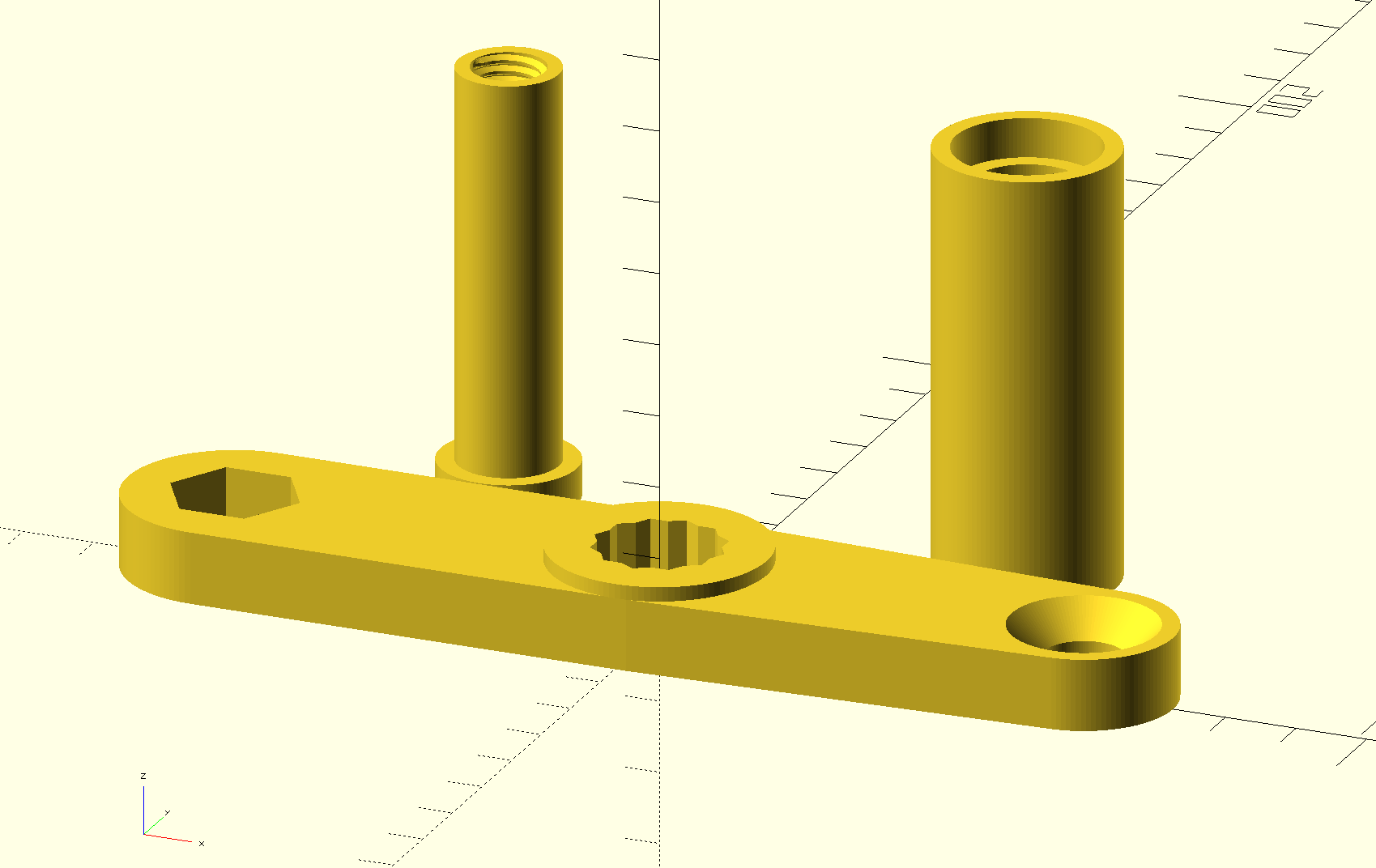
I ended up cleaning up the threads on the bolt and crank with a tap and die. If you have tuned your printer well you might not need to do that.

I’m open to suggestions for improvement!

5 Likes

No love for youmagine.com?

The more sites I put files up on, the more likely I am to lose track of all the places. And thingiverse does to me seem to have gotten better after the indexing work they did recently.

The central socket hole is for speed; the end socket hole is for strength. I think the default should be that the central hole is twelve-pointed and the end hole is six-pointed, like this:

My son helped me to discover that the obvious weak point at the shoulder of the shoulder bolt really is too weak. :roll_eyes: So I have added a hole inside the threaded portion of the shoulder bolt into which to screw a real metal screw to add strength.

By helping discover, do you mean he used destructive testing procedures? :slight_smile:

3 Likes

“I can’t remember how it broke!”

“I’m not angry, I just need to understand what happened so I can improve it!”

The reinforcement seems good now. I consider the design work done now, until such time as I break it. :roll_eyes:

4 Likes

Update: I printed two of these on the theory that the PLA I used was likely to break from me pushing too hard on it, expecting that to last a few weeks, maybe a month before I milled and lathed a replacement out of aluminum.

I think I can count on the fingers of one hand the times I’ve used the big metal handle on the vise since February, mostly when I need to mill steel with very little purchase in the vise jaws and just want to make sure it’s very tight. I’ve rarely even used the six-pointed socket at the end of the handle. I haven’t even broken out the reserve plastic handle, let alone started on an aluminum version. I’ve leaned into the center 12-point socket pretty hard and it’s holding up great.

It’s light weight, runs fast, is a convenient size, doesn’t get in the way.

I have no plans now to make one in aluminum. I’m very satisfied with the printed version.

1 Like

Last weekend, another one of my kids was using the mill and leaned hard enough on the speed handle to break it, so after more than three years of use, I’m on to the backup printed handle.

However, I’ve realized that I made it way too complicated. I should have just put a large screw through the back, not tried to reinforce a shoulder with a small screw. So I might actually update the design to simplify it.

When I do that, I’ll probably also make the 12-point socket deeper, which will do dual duty; both making the socket stronger and holding the handle away from the flange of the vise.

1 Like

When I first made this, it broke, so to make the existing design stronger, I embedded a smaller metal screw for strength inside a 3d-printed screw. This was needless complexity! I was constrained by my initial idea. It did last three years, so yay! But now I’ve come up with a modified design that is less complex and yet more robust.

I have some extra M10x30 countersink screws from my outrigger vise stop project (that will be another post when I finish it…) so I used those in the design, but you can just choose your screw and thread profile if you make your own. With OpenSCAD nightly builds now enabling the Manifold kernel, even though I’m modeling threads, rendering is almost instantaneous!

As assembled:

As printed:

Note the heavily-chamfered hole for the countersink M10 screw.

2 Likes

Oh my. With Manifold, I can add chamfers using minkowski without going out for lunch while it renders!

Files are updated at all sites.

2 Likes