Originally shared by Sebastian Szafran
Finally, TinyG2 (ArduinoDue+gShield) working OK.
First of all I would like to express my huge appreciation to @Alden_Hart for his immediate support and for explaining in details the way TinyG2 works.
It looks that the wiring method I am using in my setup (NC switches wired with pull-down resistors to GND and switch mode in settings.h set to ACTIVE_LOW) has not been described.
I have to state here that the method of wiring NC switches with pull-up resistors connected to VCC and switch mode in settings.h set to ACTIVE_HIGH, which is presented in the source files comments did not work for me. It conflicted with the probing process.
I am using two NC switches for each axis wired in series thus both sharing a single pin of the microcontroller. This way I do not need to use Xmx, Ymx and Zmx can be used for Z-axis limit switches. Zmn is used as PROBE pin.
Here is how I made my setup:
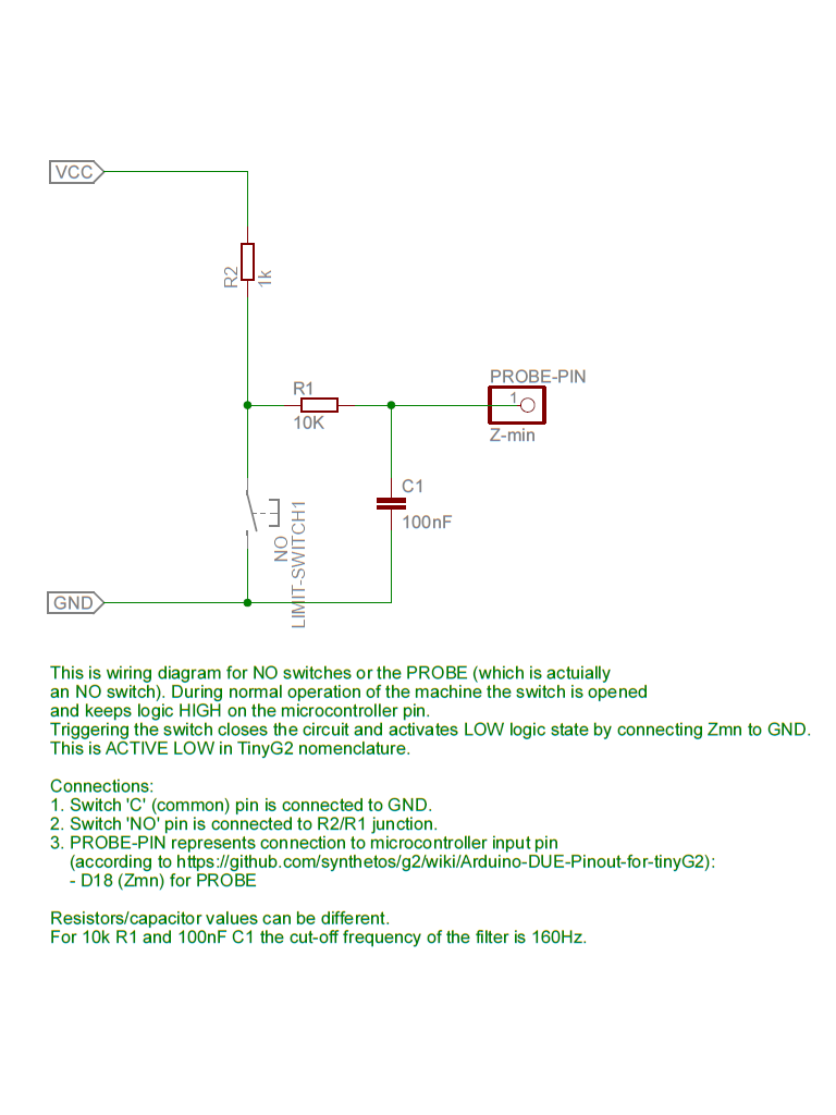
- I wired all connections according to diagrams attached below to this post.
- I adapted settings in the settings/settings_default.h (alternatively you may wish to create your own settings-OWN.h file by copying existing file) related to limit switches pins and probe pin configuration:
// Xmin on v9 board
#define DI1_MODE INPUT_ACTIVE_LOW //NC switch wired with pull-down resistor
#define DI1_ACTION INPUT_ACTION_STOP // STOP
#define DI1_FUNCTION INPUT_FUNCTION_LIMIT // LIMIT
// Xmax
#define DI2_MODE INPUT_MODE_DISABLED
#define DI2_ACTION INPUT_ACTION_NONE
#define DI2_FUNCTION INPUT_FUNCTION_NONE
// Ymin
#define DI3_MODE INPUT_ACTIVE_LOW //NC switch wired with pull-down resistor
#define DI3_ACTION INPUT_ACTION_STOP
#define DI3_FUNCTION INPUT_FUNCTION_LIMIT
// Ymax
#define DI4_MODE INPUT_MODE_DISABLED
#define DI4_ACTION INPUT_ACTION_NONE
#define DI4_FUNCTION INPUT_FUNCTION_NONE
// Zmin
#define DI5_MODE INPUT_ACTIVE_LOW //Z probe (NO) wired with pull-up resistors
#define DI5_ACTION INPUT_ACTION_NONE
#define DI5_FUNCTION INPUT_FUNCTION_NONE
// Zmax
#define DI6_MODE INPUT_ACTIVE_LOW //NC switch wired with pull-down resistor
#define DI6_ACTION INPUT_ACTION_STOP
#define DI6_FUNCTION INPUT_FUNCTION_LIMIT
With this setup the limit action triggers every time a limit switch gets hit and the machine gets SHUTDOWN state. Homing works fine, too. The PCB probing works as expected,
I did not get any false positive since I have set it all up. My limit switches are all enabled in the configuration ($lim=1).
Why I prefer using NC switches? If the wire gets accidently disconnected/broken the machine will report ‘limit action’ and remain in SHUTDOWN state until the wiring is repaired or the user clears the alarm with $clear. But even so, a user will be aware of the problem.