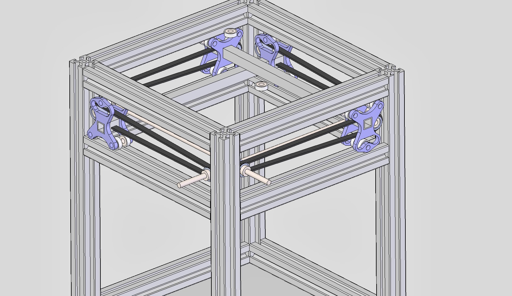
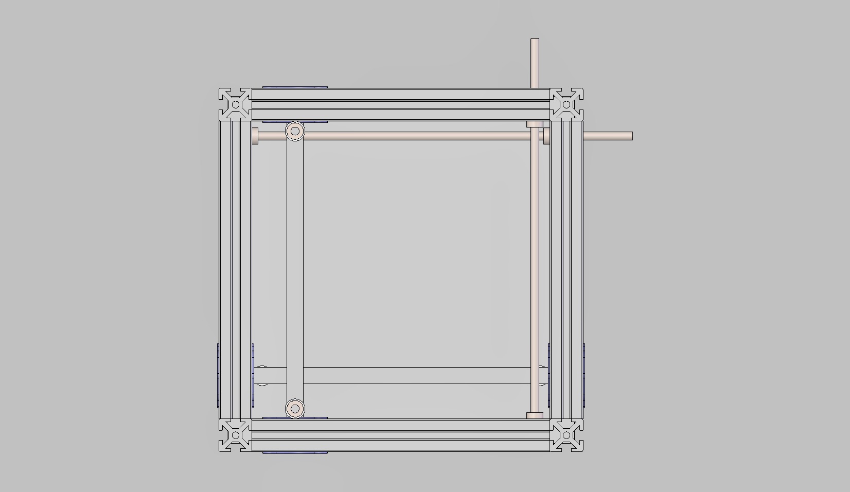
OK, here’s the idea I got based on the work @Shauki has been doing on his Quadrap. There’s still a ton of work to be done here, but I’ve at least worked out that it all fits together without interference. Clearance is a little tight. There’s 2 mm between the beams and 0.5 mm between the Ø5 mm shafts.
Right now, the moving mass is a few dozen grams more than his, but I have much smaller drive pulleys. So he should have higher travel speed, and I should be able to accelerate faster with the same steppers.
I’m still planning the same overall frame dimensions as Ingentis. I have the frame scrunched together to keep everything in view at the same time. Compared to Ingentis, this is using 19 mm less vertical space and perhaps 45 mm less horizontal space. I’ll have a better number on that when I get an extruder carriage worked out. I don’t intend to mount a Kraken.
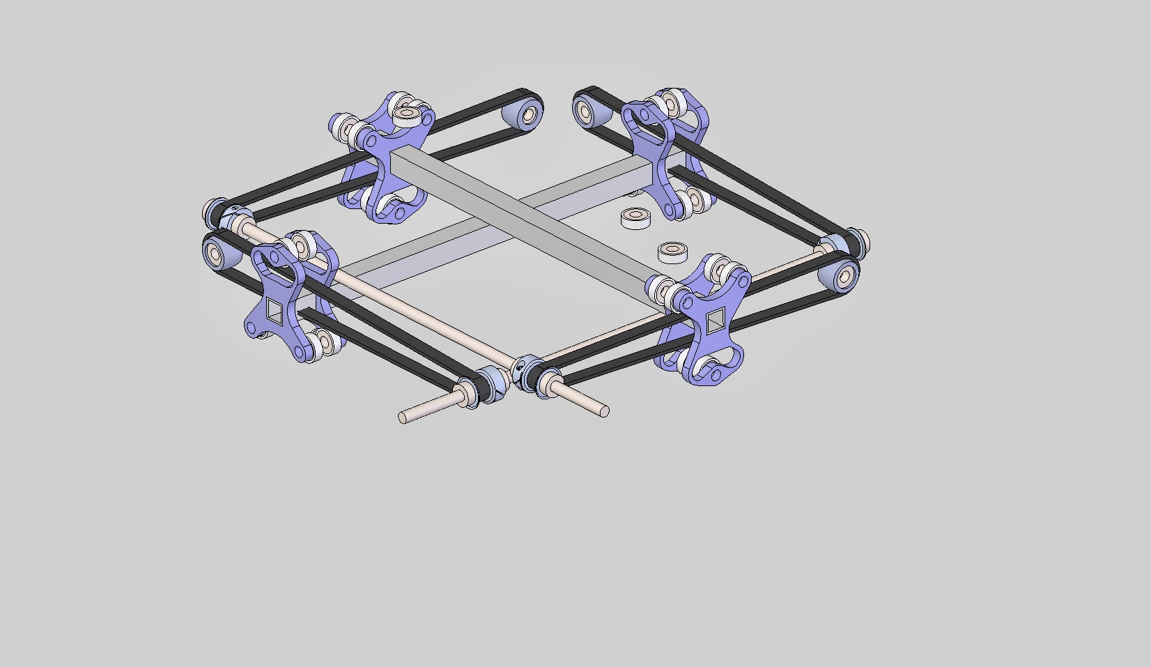
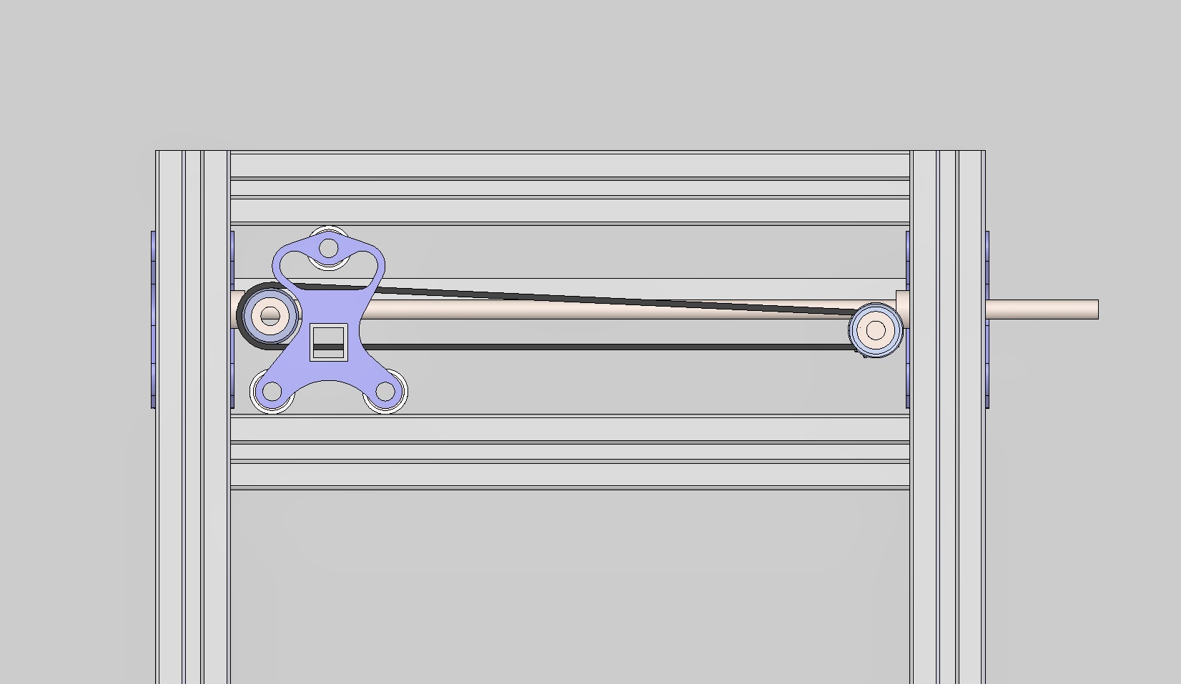
The drive pulleys are 15 tooth, 2 mm GT2, and all the bearings are 5x10x4 MR1052RS. Happily, the Ø10 mm bearing rods and their cost are gone.
That is a lot of rolling bearings Dale. How many exactly? I want to see this built, it’s only by testing the edges that we progress. Could you get away with a printed collar that goes around the bearings that allows them to sit in the tslot groove, with a v cross section or similar? Then you’d only need half as many bearings and you might not need those floating ones that I assume will stop the carriages falling out.
I forgot who did a design with the bearings tidying on the tslot, I know it was a delta printer, but the bearings did in fact wear out the extrusion over time. It was die to the fact that the actual surface area of contact was so tiny. Literary two point loads instead of 2 line loads of the bearing had its whole width on the extrusion
Also something to keep in mind, your drive pulley is a different diameter than your idler pulley, so you’ll have to account for that gear reduction on your x and y steps in your firmware as outs not 1 to 1.
@ThantiK Thanks for the compliment on the part designs, but they’re really just placeholders for now. They’ll get uglier as they near completion. Speaking of ugly, I’ll admit it certainly isn’t simple. In fact, I sort of expect build complexity to draw comparisons to a Sells Mendel. I’ll do what I can to keep it simple, of course.
@Shauki Rigidity should be similar to what you’re doing with Quadrap, except the tiny pulleys.
I tried to keep track of costs. In fact, I think this should be less expensive than regular Ingentis. Those Ø10 mm rods of hardened bearing steel aren’t cheap.
I did think about using V-slot extrusions, with the bearings mounted diagonally to run in the V-slot. I may still do that, but it would only reduce the bearing count by 4, increase the load on each bearing 41% (I need to examine bearing loading anyway) and limit the choices available for extrusions. I don’t want to rely on a kickstarter for a key component, though it could certainly be done with V-slot extrusion and appropriate rollers to reduce bearing count. Maybe if I rotate the extrusion 45°…
@Tim_Rastall That’s 44 of those bearings, including those used on the pulleys. You are correct about the purpose of the floaters.
I thought about trying to interact with the slot in some way, but I don’t think I can print a collar that would run smoothly. Hmm. I could probably mount it in the drill press and sand it smooth though.
If the bearing loading looks favorable after I check the numbers, I may be able to use a single bearing at each position instead of the doubles I have now. That would cut the quantity roughly in half, to the quantity I think you have in mind for the printed collar idea.
@Shauki That carriage is still a very rough design. You’re right, I can’t print a perfect square hole to fit the bar tightly. I intend to come up with a printable nearly-square hole that will grip the tube tightly. I don’t know exactly what that will be yet.
I think what you’ve described for joining the two halves may be better than what I had in mind. I was planning to connect two printed pieces in the middle, and have the axles for the bearings captured between the halves. Using screws to join the halves and serve as the axles may work out better. I’ll have to explore both paths and see which works out better. Thanks.
Hmm. I can’t lower a bearing into the bridge because the return side of the belt passes between the top roller and the bridge. Also, the carriage on one side is upside-down from the carriage on the other side, so I need to be careful that any change will work on both sides. Eventually, the upside-down carriage will be redesigned to have two rollers on the bottom, but the belt path has to stay where it is.
Sliding along a rod on the top side needs some questions answered to evaluate. What would the sliding friction be, and would there be a mass advantage? I don’t know. These are the bearings I’ve had in my R/C cars for 20 years, and they weigh almost nothing. The sliding friction would need to be tiny as well, and I still don’t know if a little drag is better than an extra sliver of mass.
Alternative ideas for the frame top is interesting. A 10x10x1 square tube turned 45° would allow the two top bearings to also guide the carriage. I need to think ahead to see how that may impact exclosure design, but I like the idea. It gets rid of the 4 “floating” bearings.
@Dale_Dunn Strike what I said, you are not driving anything with the pulleys, you are simply moving the belt unidirectionally, in which case, since the bottom of your belt is parallel with your travel motion, it is the same as if you had both pulleys the same diameter.
Just a little project update, if anyone remembers that I’m working on this: I’ve finally decided (while ruminating on my 4th carriage concept) that I’m not going to find a solution to the fatal flaw in this X/Y drive system. Namely, for a single-stepper drive for each axis, it needs a rigid shaft to couple the two belts. With this size machine, there is only room for a Ø5 shaft, about 450 or so long. Per unit volume, aluminum, carbon fiber tubes, graphite rods, etc. are too flexible. Even steel at that length and diameter would give me unacceptably large position errors under max acceleration in the far corners. To get this under control, I’d need the shaft to be tungsten carbide. I never found a supplier willing to make it more than 100mm long. Either that or start monkeying with the proportions of the structures until it’s almost unrecognizable and I’m spinning a big heavy shaft. Yes, that’s still only half the rotating mass of an Ultimaker, but I’m trying to build something that makes that look sluggish.
An alternative would be to use two steppers per axis, with the rod serving only to maintain synchronization. That would work (and the shaft could be pretty flimsy), but one of my goals is to have all the steppers packaged on the same side of the machine. I may give up on that if I decide I want to double the torque, but I’m already looking at absurdly high accelerations. Most of the additional torque would go into accelerating the extra stepper, I think. They would account for the majority of my planned moving mass.
What I’m thinking now is to drive each end of the traveling beams with loops of cable or belt that run down both sides of each axis instead of one at a time. They should be much lighter and more rigid in tension than the puny shaft is in torsion, even though the loop would have to be long enough to run down both sides and the side in between. Obvious, in retrospect. Sorry I don’t have any illustration of this, but I’m only commenting here to mark the above arrangement of shafts and belts a dead end. It’s similar to this idea for the Z axis (https://plus.google.com/107543004166274026989/posts/49hJJ4zX9qN), but not driven by a screw.
I think you’ll get much more benefit from the extra torque than I will. I don’t think moving mass on your machine will be dominated by the stepper rotors. I plan to have my moving mass extremely low, so that most of my steppers torque will be used moving the rotor. To be honest, I haven’t done the math for my design yet, in large part because I haven’t finished it. I’m sure it looks like I’m not getting anything done, but I’m iterating in CAD rather than hardware. And otherwise doing other things. But I may someday visit the idea of using two smaller steppers to get the same or similar torque with less total moment of inertia. At this rate, it’ll take me years to get there…