New Vevor 2HP 82" belt grinder

Today’s job was to fix up the platen.

It came with something soft and graphite-coated attached to the platen. A soft substrate won’t let me cut precisely, which was why I ordered the ceramic glass platen. Why does one want ceramic glass for this?

Neoceram and Pyroceram are similar glass products that have a very low coefficient of thermal expansion. Regular plate soda glass has a coefficient of thermal expansion of 9 µm/m/°C but Pyroceram’s is 0.3 µm/m/°C — 30 times less. This means that it doesn’t bow and break due to a temperature differential between the sides like regular glass would. It’s why it’s used in fireplaces. Additionally, it is very strong and does not tend to shatter; this was the first thing that was noticed (it bounced!) when it was accidentally discovered.

Sanding things heats up the platen a lot, and plate glass used for a platen will shatter. Machinists have reported over a decade of use of a single Pyroceram platen liner. These are typically attached with something a bit flexible; some use double-sided carpet tape, others use RTV silicone. Some use high-temperature epoxy. I chose high-temperature RTV silicone; the same stuff I use for sealing the bed heater edges on my 3D printers.

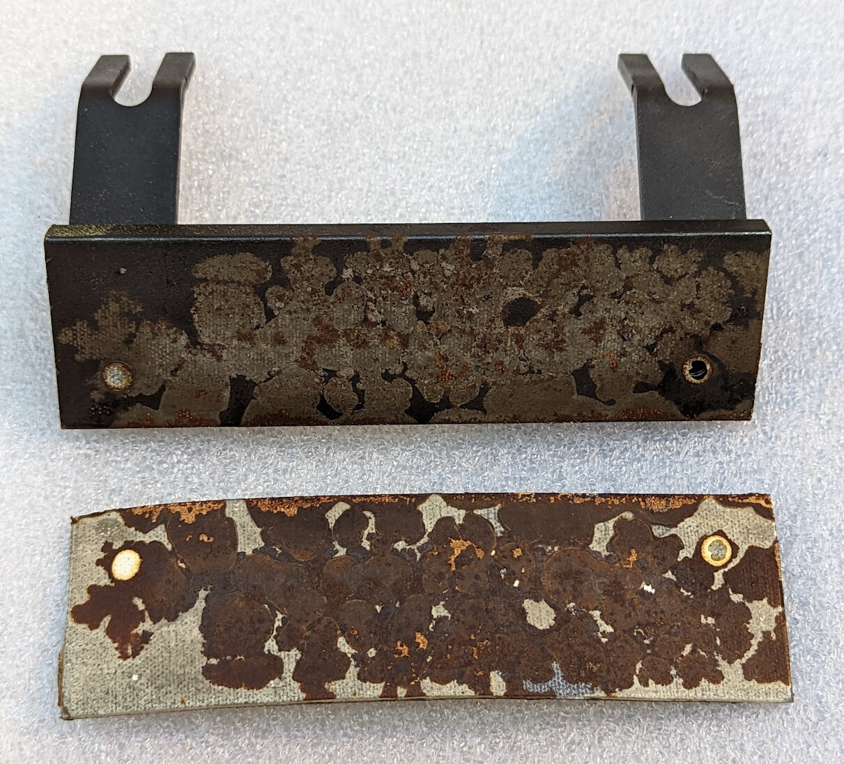
The provided graphite coating was soft, and the adhesive was perished, so it peeled away with almost no effort, revealing significant rust.

It took several skim passes with the face mill before I had a good surface.

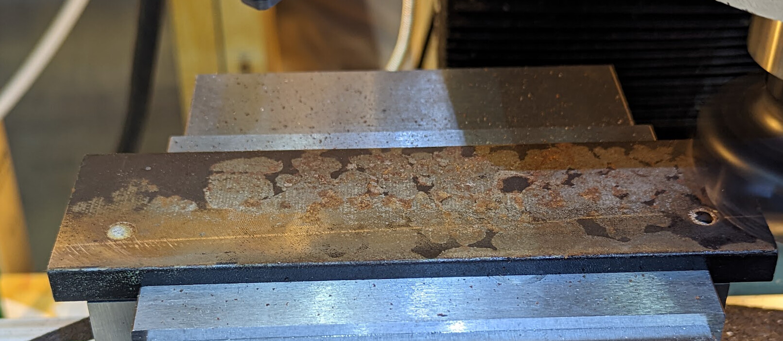
Because this was still coated in mill scale, I used regular inserts instead of polished inserts. This didn’t leave as smooth a surface, but that’s probably better for an adhesive holding on to it anyway.

I could have just polished it, since silicone would fill the gaps and make it all smooth, but what’s the point of having a face mill if I don’t use it?

Then I cut a 3/4" x 2" by 4.5mm safety shelf. (The Pyroceram is 5mm thick and the safety shelf should be slightly thinner.) Here it is mocked up before I cut the 1" down to 3/4"

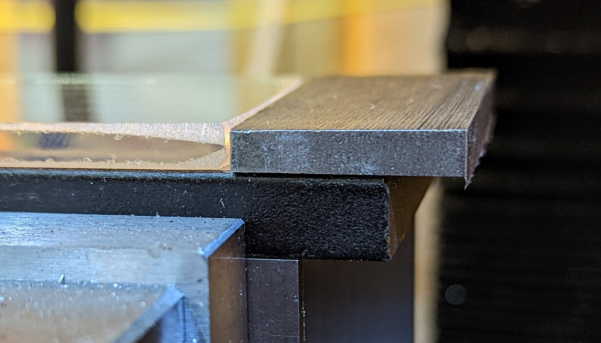
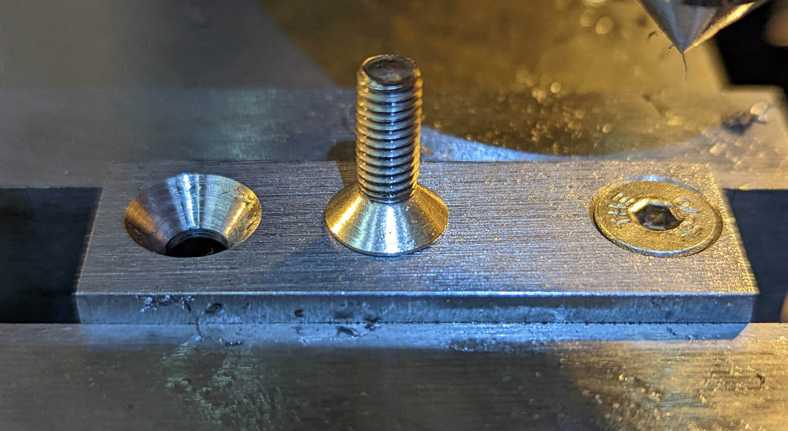
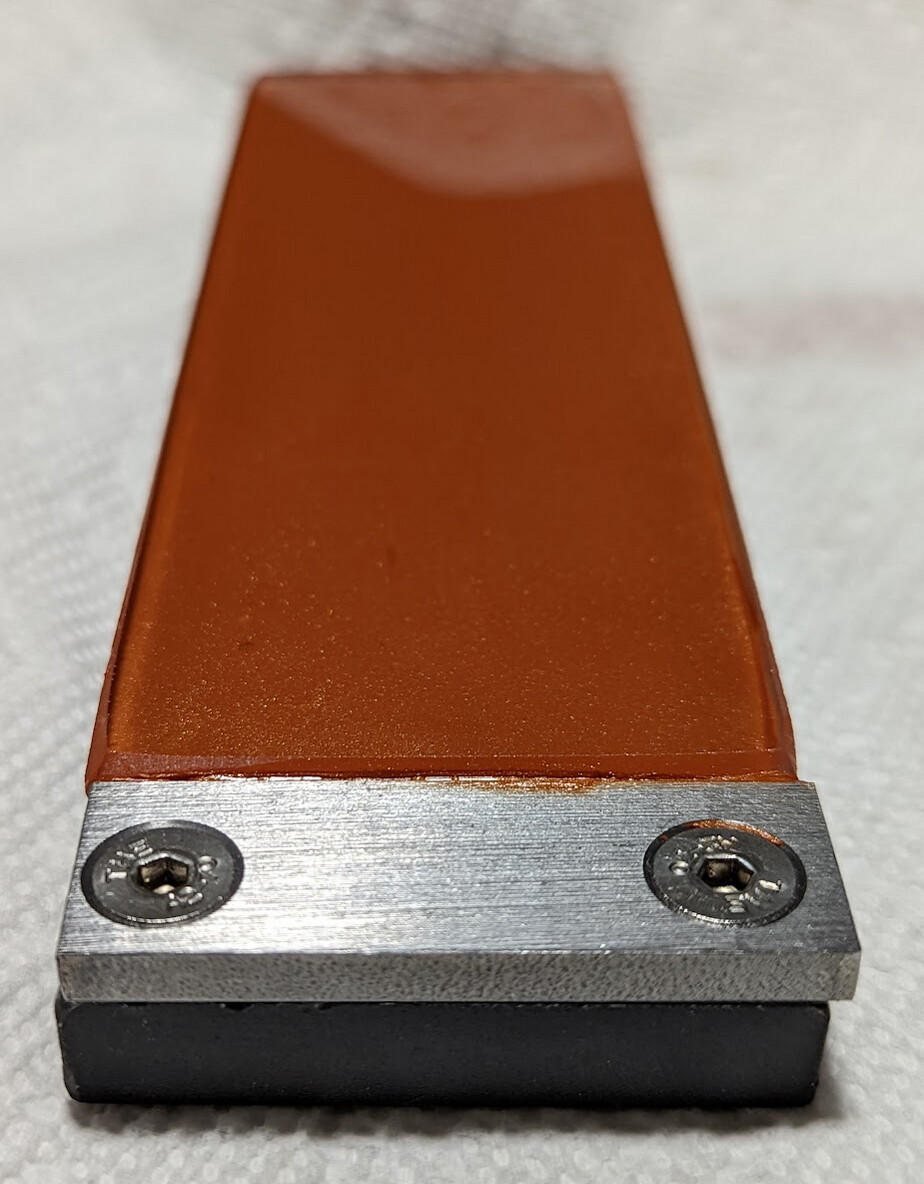
I clamped the shelf to the bare platen, drilled and tapped M5, then drilled 5mm clearance and countersunk holes for two M5 FSC (Flat Socket Countersunk) screws in the shelf, making sure that the head was slightly recessed:

Here’s the dry assembly with the shelf in place:

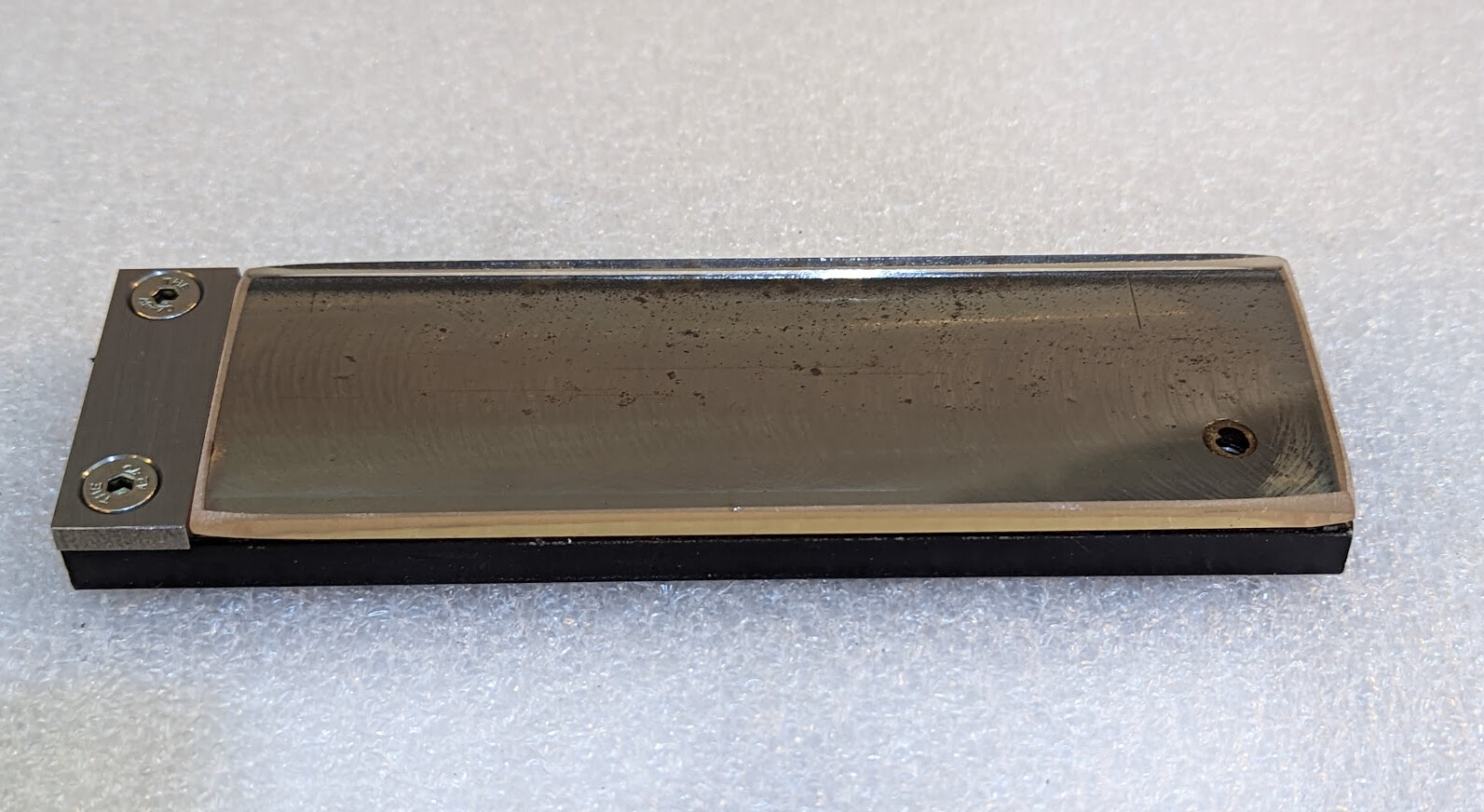
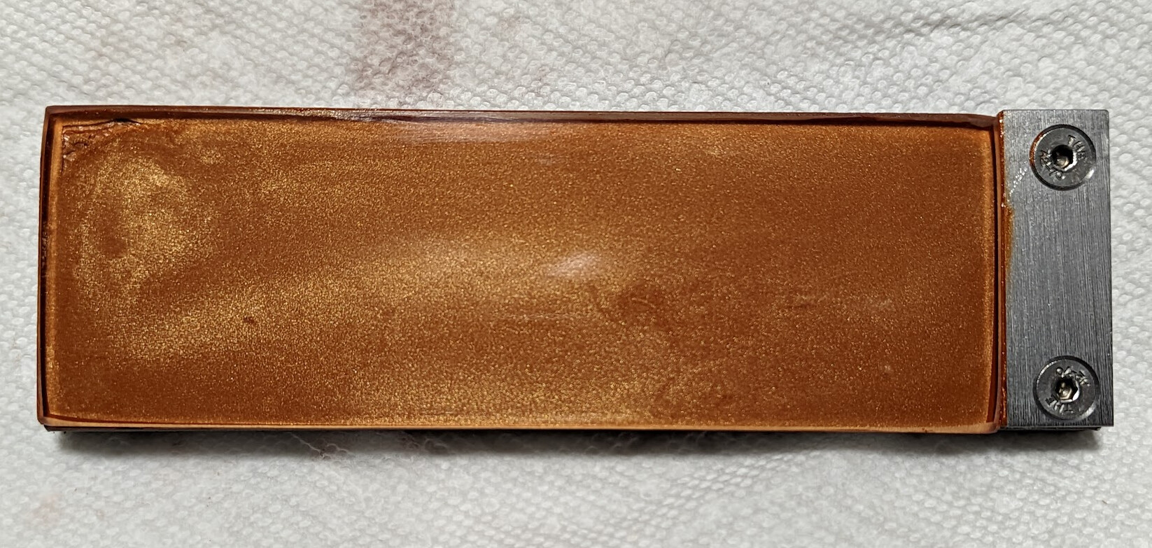
I then cleaned the glass and metal thoroughly with isopropyl alcohol, spread a thick bead of silcone on the metal, and pressed the glass down. I had to wiggle the glass back and forth until there were no air bubbles in place, but eventually I got there. This pushed some silicone between the glass and the shelf, which I think is a good idea; I intentionally left it there.

The silicone added to the size of the step between the glass and the shelf:

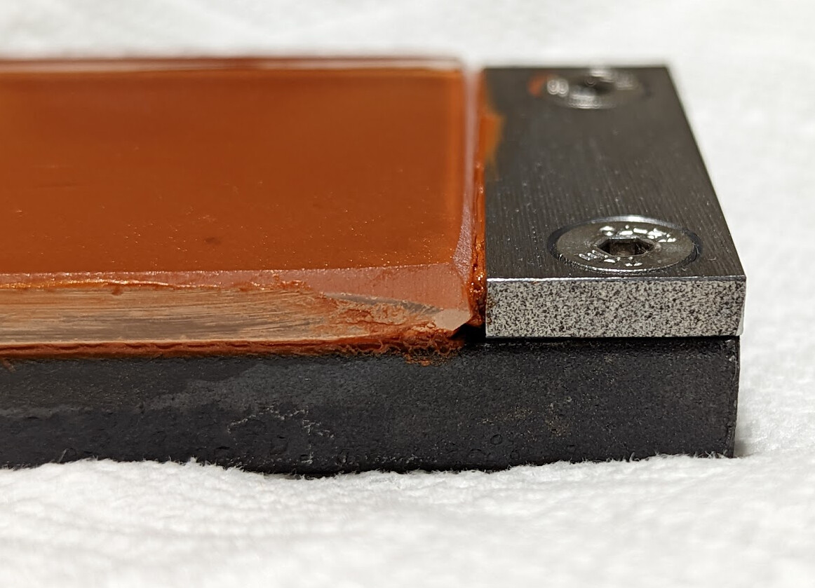
In retrospect, maybe I should have blued the shelf to match the platen, but honestly it’s not that important. I keep my shop dry, so it shouldn’t rust.

The asymmetry is because the 2" shelf is slightly wider than the platen and I decided not to bother to trim it off. The holes are symmetrical in the underlying platen, but one side of the shelf is aligned with the platen and the other sticks out.

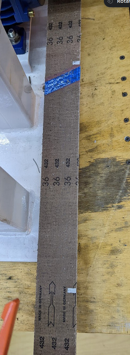
Tomorrow or the next day, after the silicone has cured, it will be ready to go back on the grinder. USPS currently expect to deliver the 4" drive wheel tomorrow, and I’ll get that mounted first. I currently expect that 72" belts will fit without any other adjustments with the 4" drive wheel mounted. :crossed_fingers:

3 Likes

Thanks for sharing your journey on this. I’ve been learning quite a few things about belt grinders of which I was unaware. :grinning:

2 Likes

I asked Red Label about their EdgeCore ceramic belts and HSS, and they quickly responded:

We recommend any hardened steels for a minimum to be around the 1500 to 2500 SFPM. However those Ceramic belts should perform the best in the 3600-4500 area, but it can also depend on the grit:

Coarser belts around 36 grit → 4500 SFPM
80 and 120 grit → 3600 SFPM

I clearly need an optical tach now, so that I can work out RPM. Or I could put 6 evenly-spaced tach reflectors on the inside of the belt, in which case an optical tach would actually read SFPM directly from the inside of the belt. :open_mouth:

It is quite possible that in the end I’ll want to use the 220mm wheel for working HSS, and the 4" wheel for mild and tool steel. If I get to that point, I will have to modify the unit to support 72" belts, and I’ll want to find the smallest necessary change to do that.

The 4" wheel arrived today. I’m impressed with how quickly it was sent, and it was well packaged.

The new wheel was, like the original, a tight fit on the motor shaft, so I ran the motor without a wheel and used scotchbrite to clean up the motor shaft until both wheels slid on easily. This also deburred the keyway, making the key fit better. It also looks much better. :smiley:

The bad news is that I hadn’t noticed that the 220mm wheel overlaps the motor case slightly, but that part of the case is larger than 4mm. So even with the 4" wheel installed as close to the motor as it can go, the belt wants to rub on the motor case. I’ll have to work through the options here. I think I do want the 4" wheel for some uses though! So it’s worth thinking through.

Additionally, the set screw hole in the new 4" wheel wasn’t tapped through, so it can’t lock to the shaft. Oops. And I don’t have long taps to easily finish the job. I’ll see what the seller says. [Edit: Offered partial refund, which easily covered the cost of a tap. Would buy again.]

2 Likes

While I found that it is possible to run the 72x2 belt on the 4" wheel without hitting the motor housing, it ran at the inside of the drive wheel and off the outside of the tracking wheel, so it’s obviously putting inconsistent tension on the belt and I would expect that to create subtle errors when grinding. So fixing it seems prudent.

If I make spacers for the wheels to hold them away from the motor 5mm or 1/4", and a new tracking wheel axle with a 5mm or 1/4" wider shoulder for the tracking arm, then I should be able to switch between wheels easily, just installing the correct spacer for the wheel in use.

Removing the tracking wheel axle was a production. It is held on with a circlip, so I thought it would be easy. Instead, I had to remove the whole hinge assembly and again resort to the hydraulic press, and it took a lot of pressure. I’m sure that in any case, taking some scotchbrite to this axle would be a good idea.

The axle journals are 25mm for the 6205 bearings on the wheel. The thread on the end is M16x2, with 7/8" flats, and an M16x2 thread nyloc nut that I hope is really a very loose 24mm nut but which 15/16" seemed to fit better. :grimacing:

Without modeling the threads, here’s the existing axle:

I would instead make this similar shape:

This ought to be within my abilities to make on the lathe, plus the mill to cut the flats.

2 Likes

It works.

I took a “short cut” of putting the wheel on and scribing the edge of the wheel to know where to put the circlip groove instead of measuring it, not realizing that it was the outer edge of the groove that was critical so that it the circlip would bear against the wheel and keep it from shifting back and forth. (I worked around that with a small spacer.) Other than that mistake, it works well.

I didn’t bother with the narrow section of relief in the axle. I made the non-critical widest dimension wider, 30 mm instead of 27, because it just didn’t matter and why not have more shoulder?

I die-cut the threads in order to not fiddle with change gears. If I had this to do over I might change the change gears and single-point the threads just for the fun of it, but the die worked fine.

Here’s the model and drawing I would start from if I had to do this over again. It has more chamfers in it, and it identifies the critical dimensions.

Axle.FCStd (51.6 KB)
Axle.pdf (23.7 KB)

3 Likes

Here is full speed. This is actually reading SFM not RPM:

Running more sedately:

3 Likes

The new tracking wheel axle was completely unnecessary. All that was necessary was moving the motor — there was plenty of room in the slots to move the motor not to need to change where the tracking wheel should go.

Incidentally, the price is now down to $887.99.

The 4" wheel I bought is now out of stock. Here’s one that is in stock:

Vevor also sells a set that includes such a drive wheel, but as far as I can tell not the drive wheel itself separately.

3 Likes