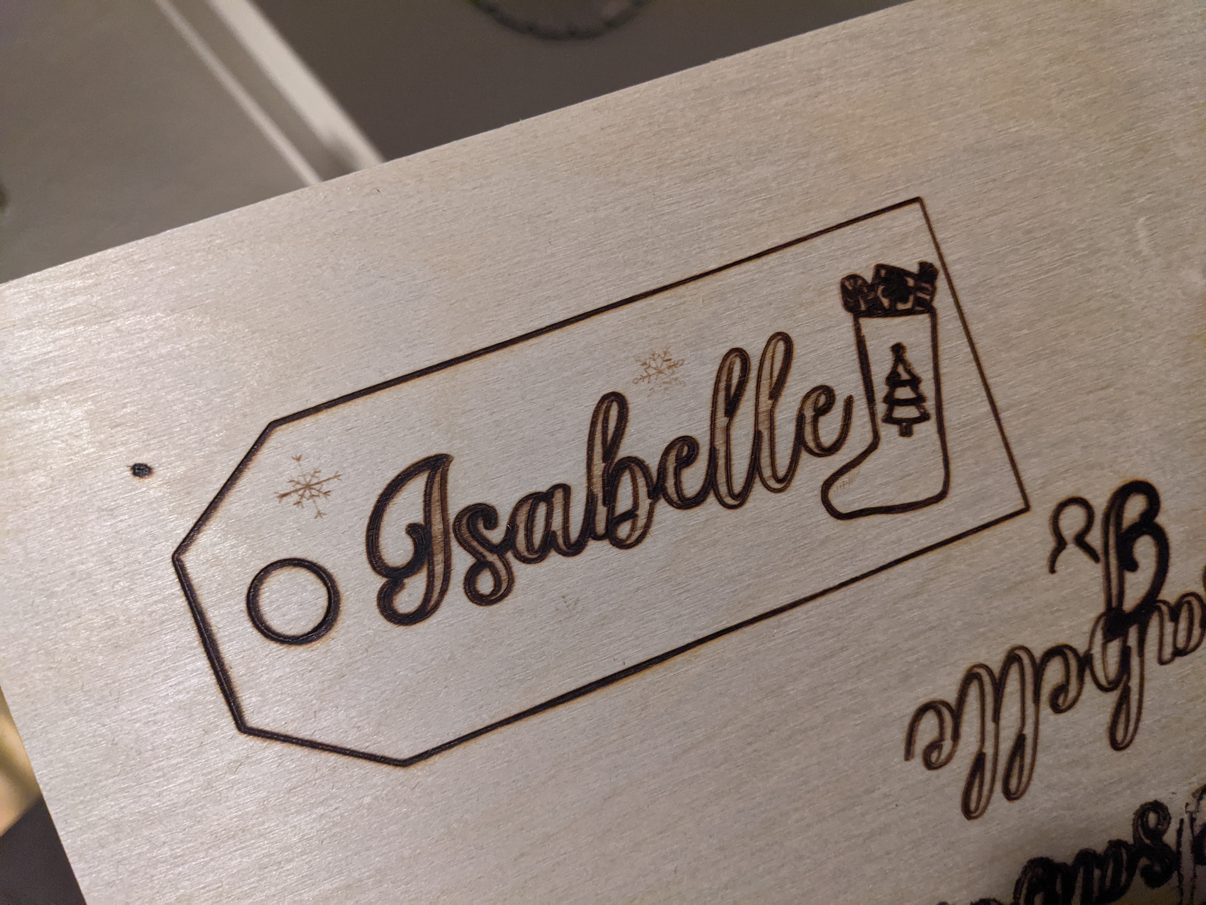
Hello - after lots of research and planning I finally bought my K40 laser this week - before switching it on I got an electrician to check it was grounded and wired safely - figured out how to install the air assist and got a new honeycomb bed … I got to switch it on for the first time tonight and it’s not quite got the power yet, it may be my focal length + alignment, which I’m going to start fresh with tomorrow - pretty tired right now after figuring all this out today! The worrying thing is I had it on 8mm/s @ 80% power and it just made a slight burn outline  the raster engrave could only achieve a shaded look, and again the was 35mm/s @ 70% power - I’ve definitely got something wrong, and experienced laser master advice would be really appreciated! I really want to make laser cut jewellery to sell in my business and was so excited to get the machine, but that seems a long way off at the moment
  … I’ll try and take pictures of my set up … thanks so much in advance if anyone can help, Donna x

Not knowing what the orginal image is supposed to look like I see the following:
- Change in line width from left to right.
- Uneven shading
I would start by doing a complete optical alignment. Seldom do these machines work as expected without an alignment.
Post pictures of the beam burn at each mirror, then we can advise from there.
Aww thank you so much for replying - I’ll do that tomorrow and post pictures of how it goes - I’ve watched some tutorials on how to align the beam so I’ll give it a go!
Yes the left side seems darker, and the line width it quite thick,
Thanks again, I’ll post again tomorrow x
Here’s some helpful information on alignment from K40 initial setup and regular maintenance: Alignment
The path that the laser takes along three mirrors and the lens needs to be precisely aligned. Here are three resources that may help you understand how to do this.
If you prefer video instruction:
Ep6: Laser Beam Alignment. The DIY CO2 Laser Cutter / Engraver Build Series
If you prefer written instruction, here are two guides:
- The “Tim the Floating Wombat” guide: K40-Alignment-Instructions.pdf
- The “smokeandmirrors” guide: laseralignment.pdf
Note that if the third mirror does not align the beam with the middle of the lens, the beam will not be focused correctly and will not be aligned with the hole in the nozzle. You may wish to use a device that helps you align using a red visible laser. One kind uses a “beam combiner” that slightly reduces beam power, and the other is a tool used only while performing alignment .

The first things I ask new K40 users are:
-
Do you have the 30mA meter installed and are you keeping it below 18mA? Anything over 18ma for a stock tube will reduce the tube lifespan quickly. Also keep the water temp BELOW 25C this will also effect tube lifespan and also effect output power. Optimal power seems to be at ~20C.
-
Did you do a quick mirror alignment check just to know the beam is mostly hitting the mirrors correctly, is a single dot, and especially is it hitting the center of the final laserhead mirror correctly. If it’s not it could end up bouncing off the sides of the tube and/or nozzle.
-
Did you do a ramp test to find out exactly where your focus point is as measured from some point on your laser head? When you do the ramp test, you can see the narrowest part of the line so move the laser head manually back to that position(use the test button if you don’t have a red dot laser ). Then measure from the thinnest part of the line straight up to some comfortable point on the laser head. It can be the bottom of the nozzle, the horizontal mounting plate holding the laser head or any other fixed point on the laser head carriage.
Thank you so much - I’ll give this a good read before I start this morning - feeling re-energised today! Hehe … x
Hi, thank you for all this info  … no sadly I don’t have the analogue Amp meter, its the digital power percentage - I’m trying to not take it over 85% power to try and preserve the CO2 on the tube longer
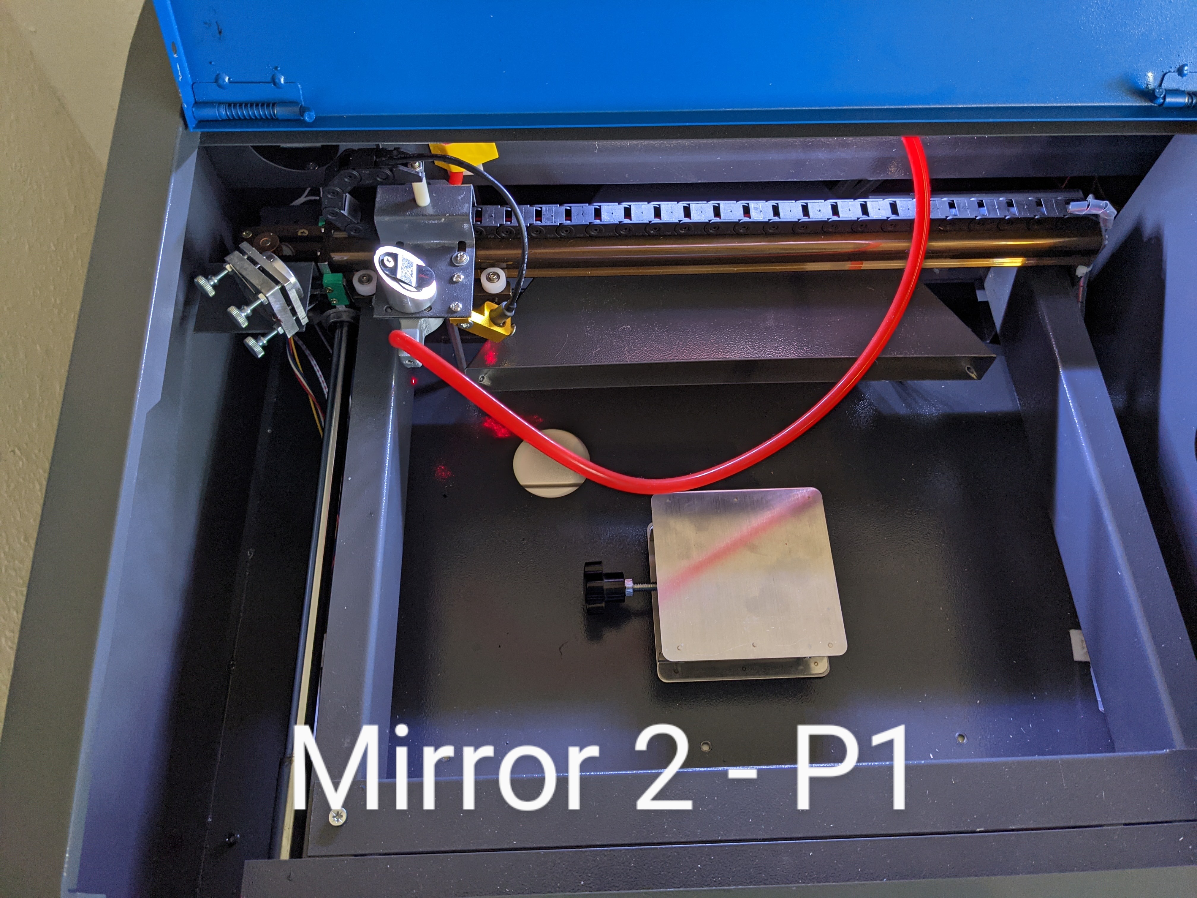
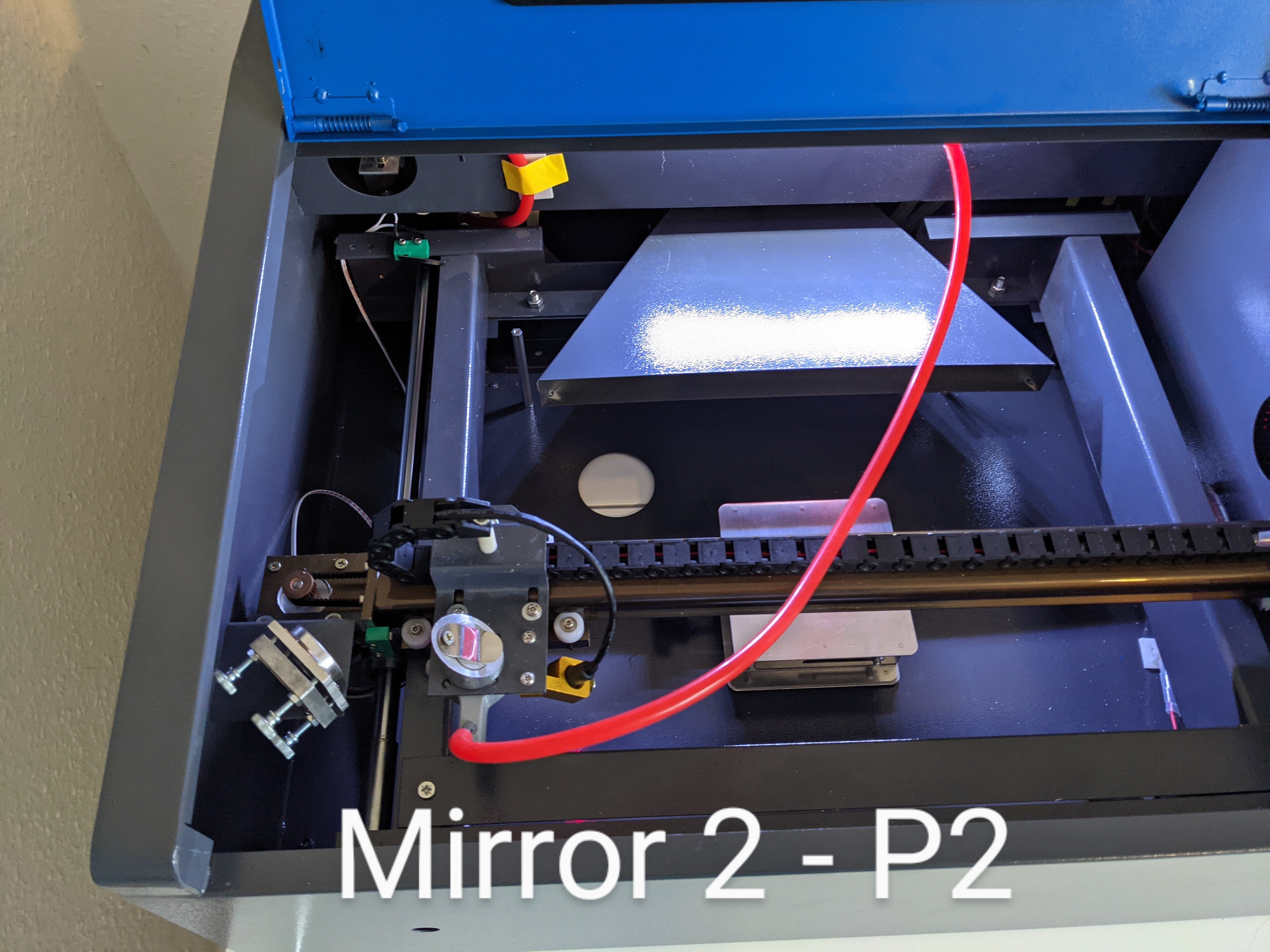
I did a quick mirror check yesterday and the dots are centred for mirror 2 + 3 - I need to do a proper alignment today tho, I’ll see if I can get the 2 dots centred at both extremes - this might take me a while! I’m a little concerned about centering mirror 3, as it isn’t adjustable?
After the mirrors I’ll check the focus with the ramp method - thank you this is really helpful
I’m hoping to get a cut by the end of today, fingers crossed!! I’ll keep you posted xx
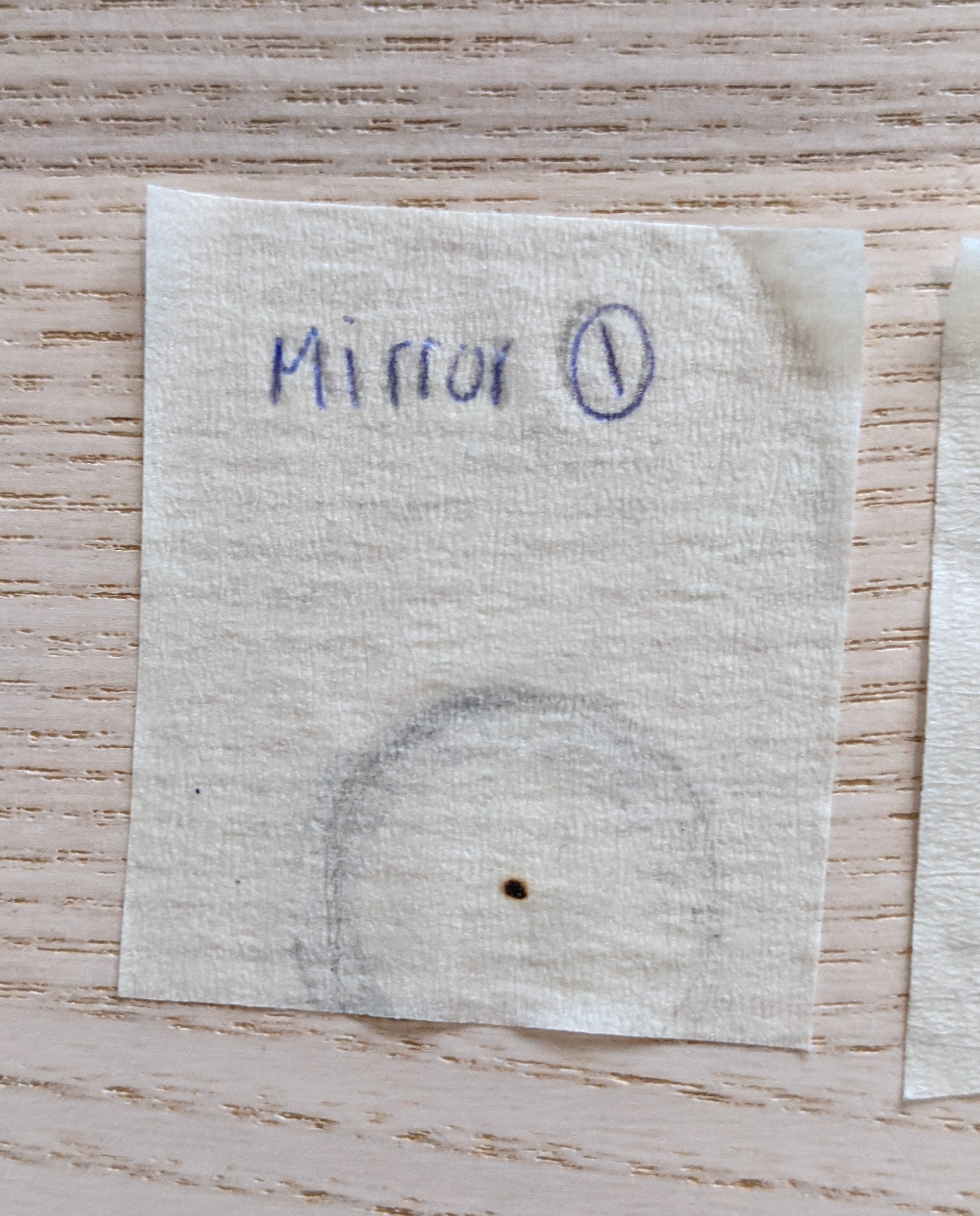
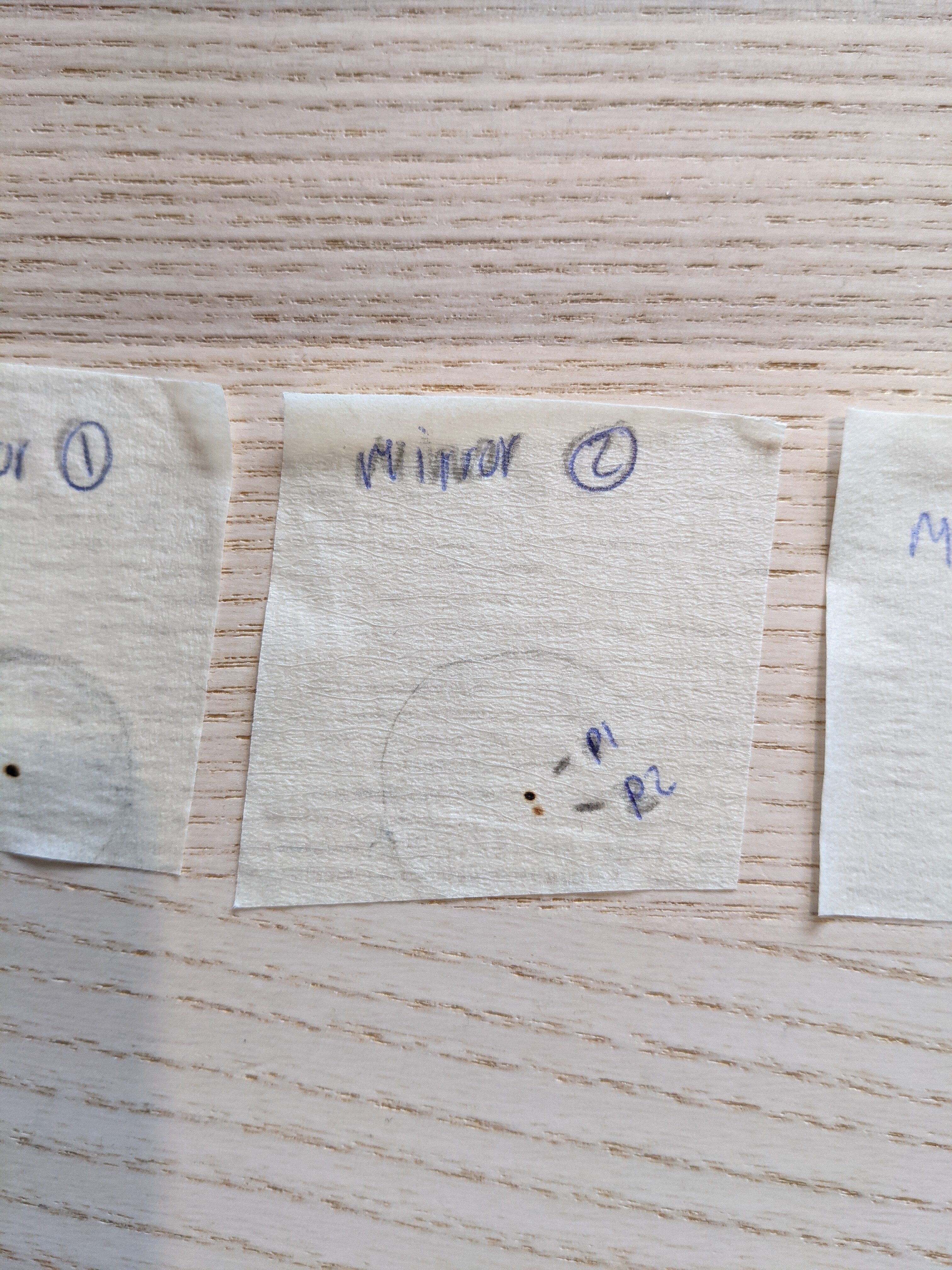
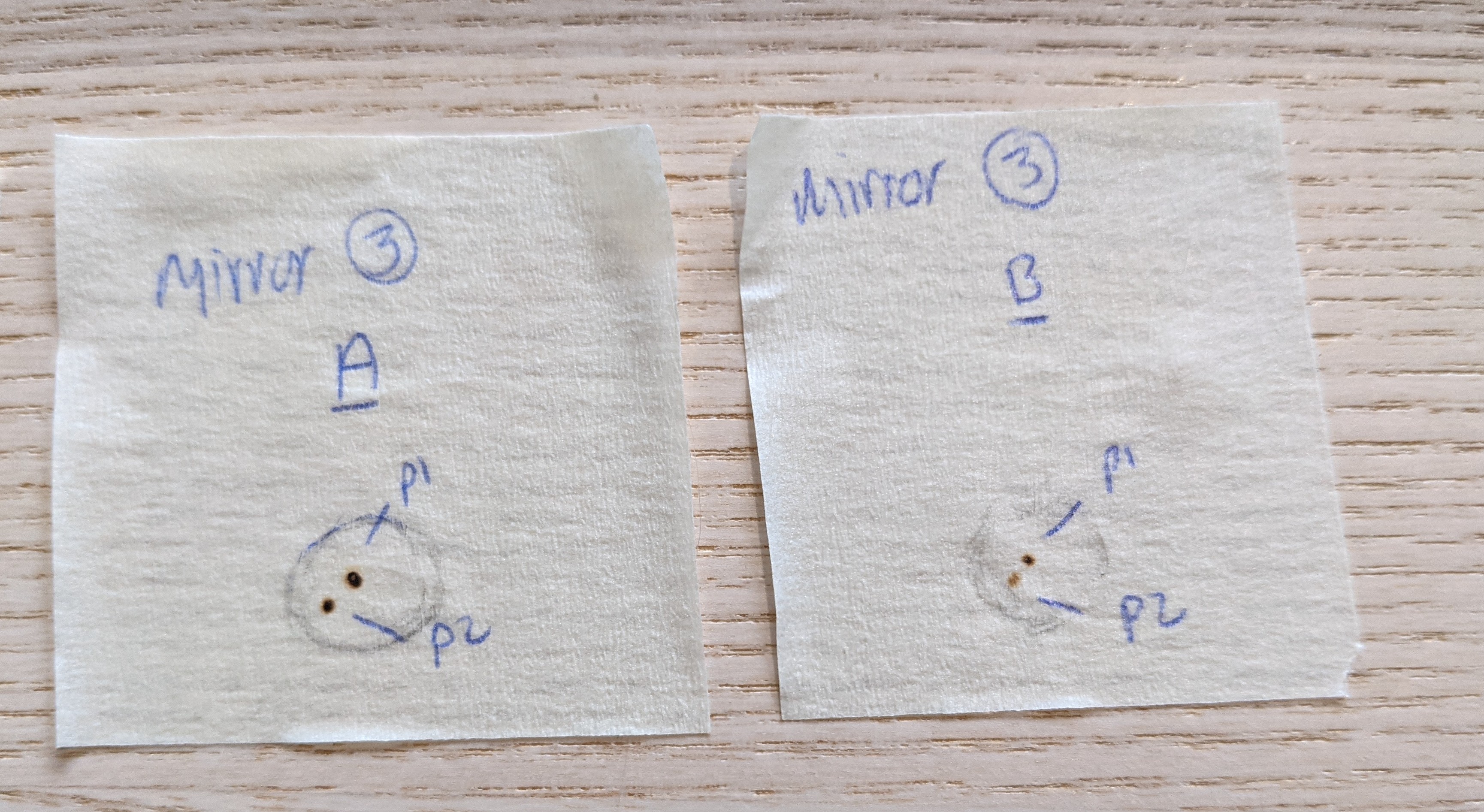
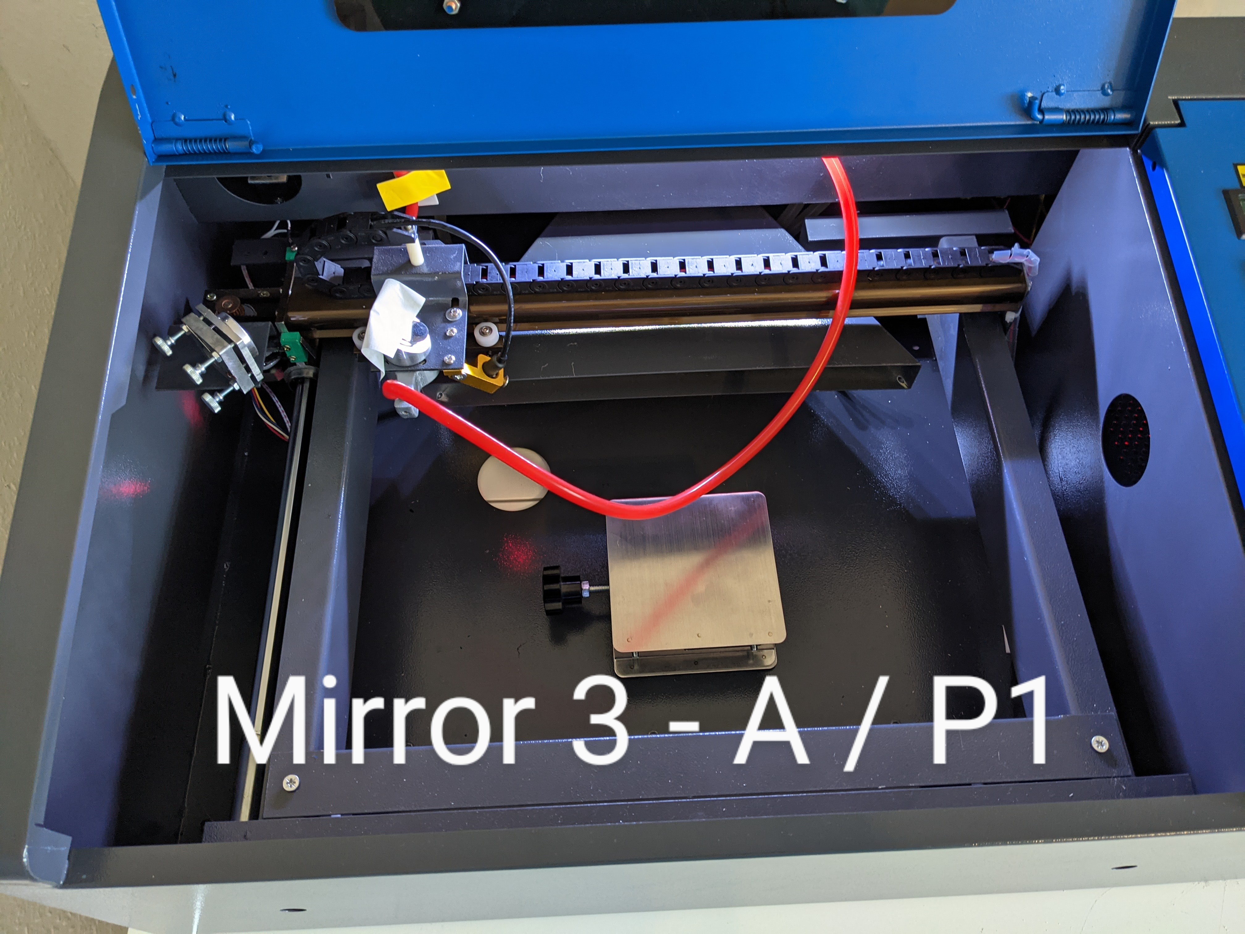
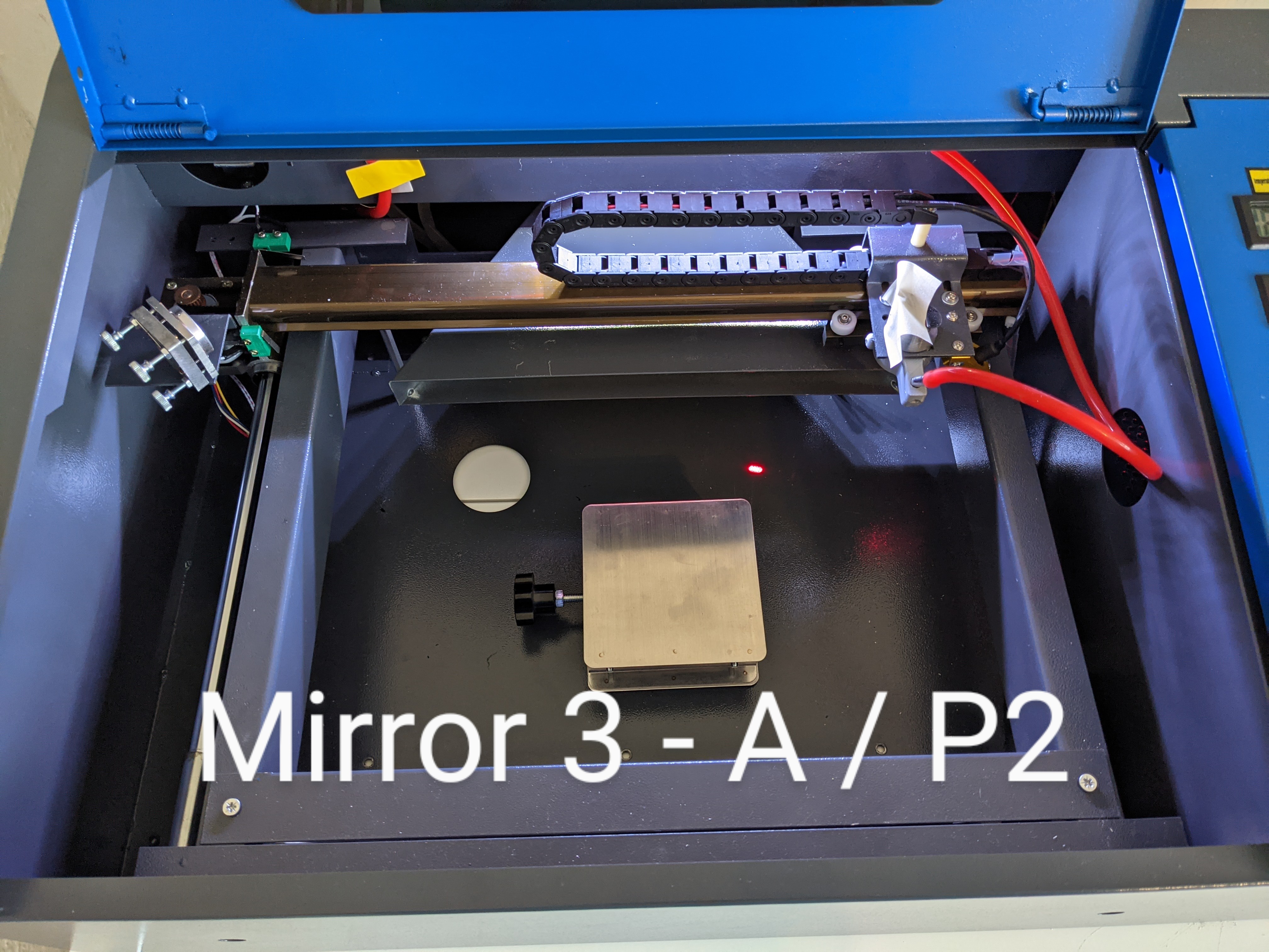
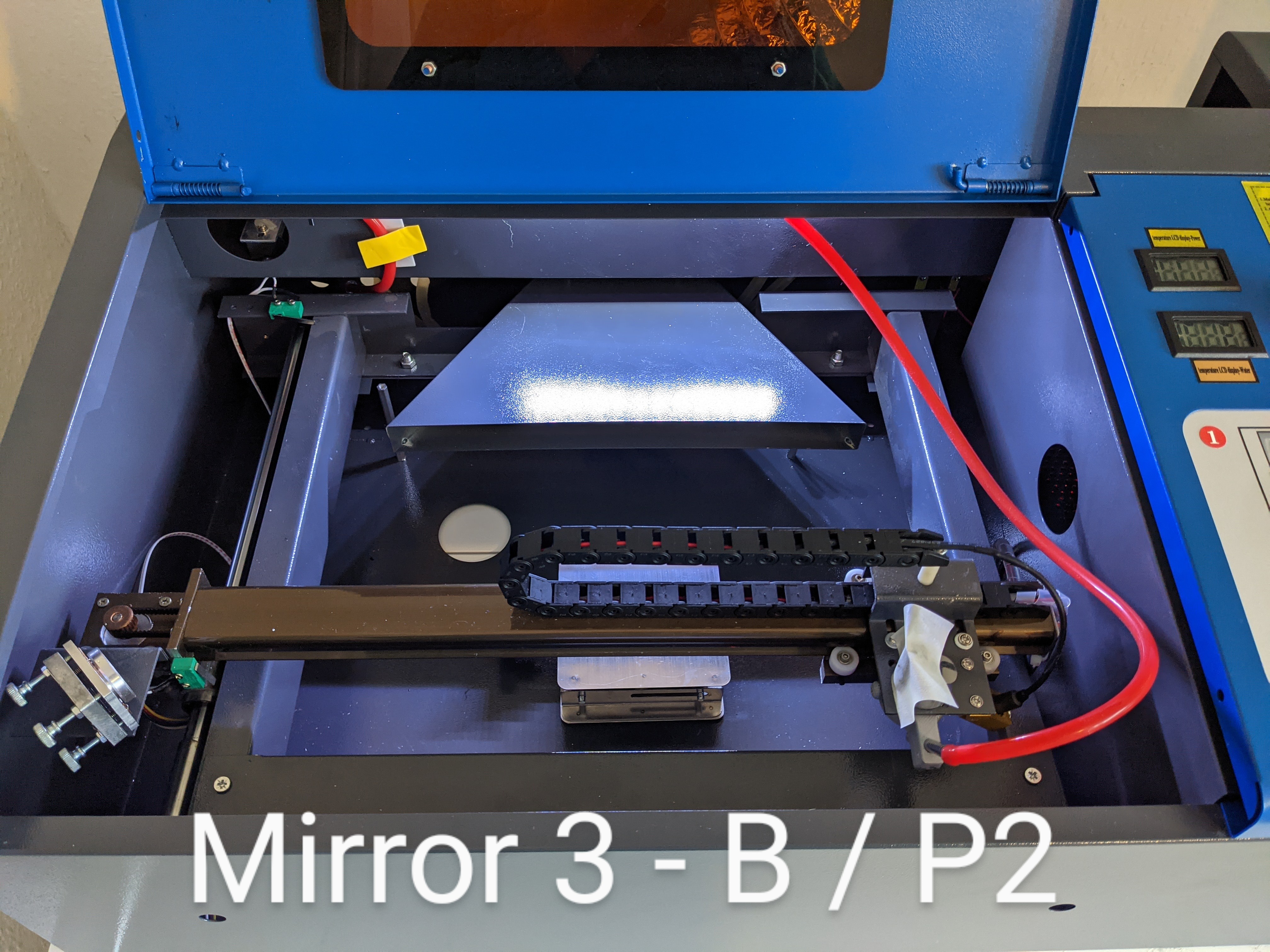
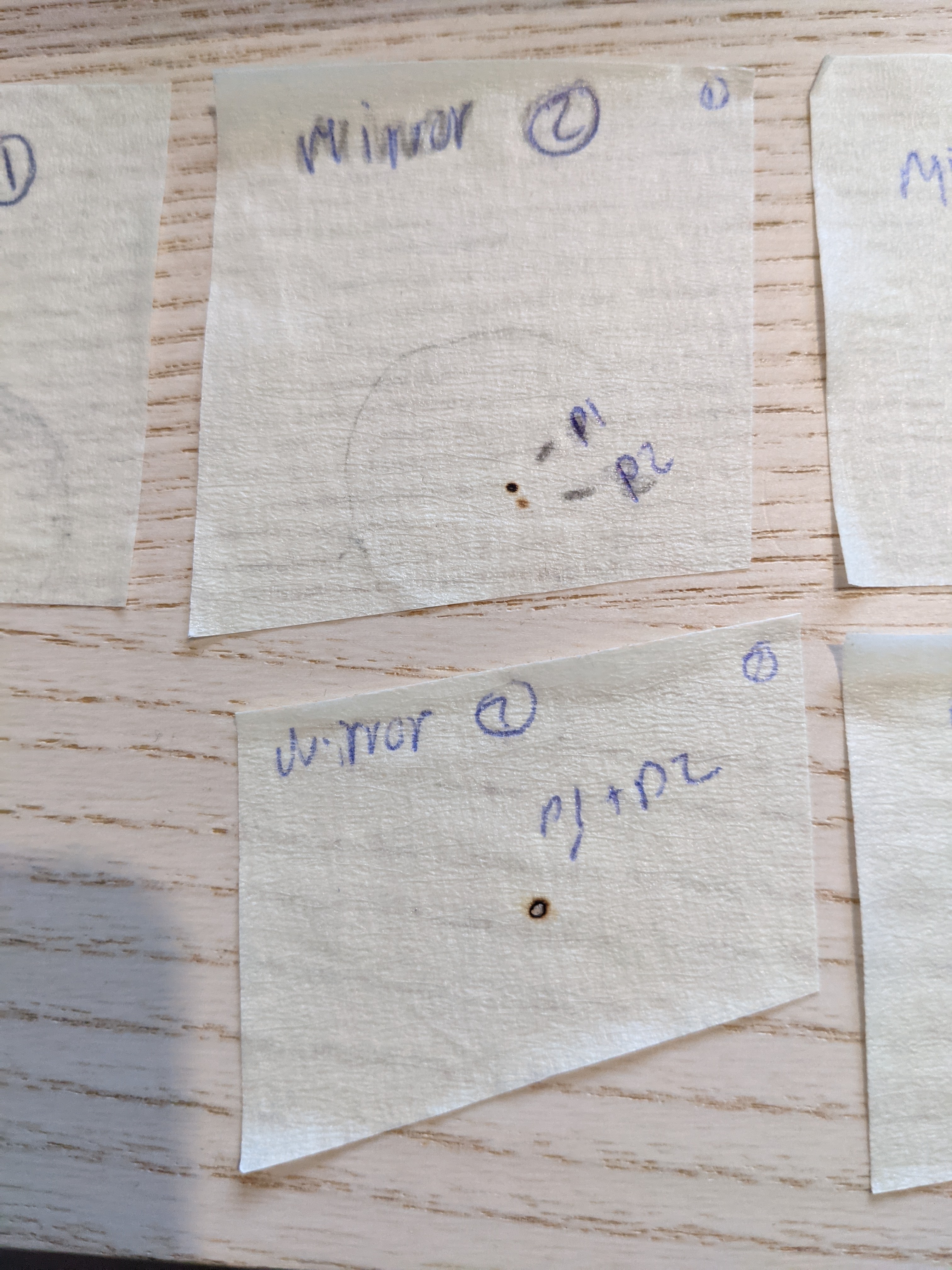
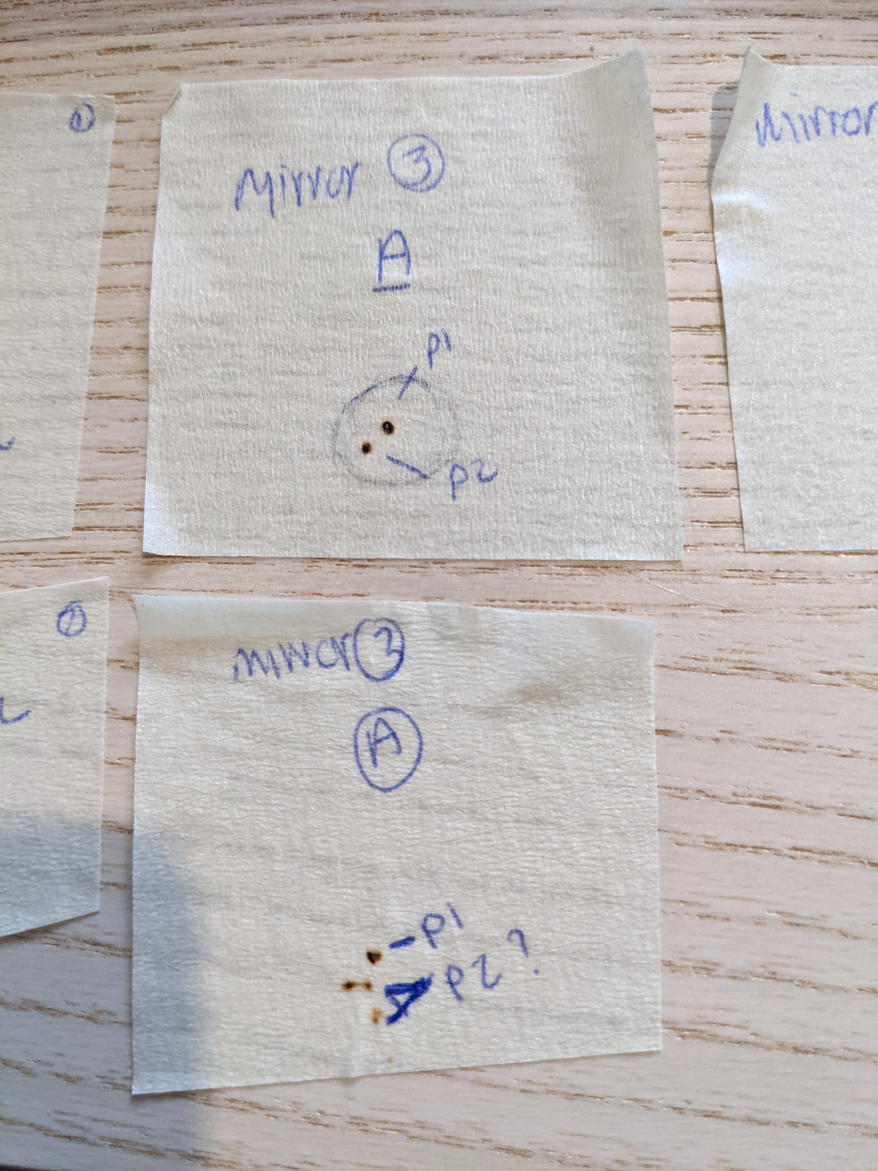
Hi guys - I’ve just done the test shots - was this the right way to start?
Settings + Mirror 1
PXL_20211123_112141409|375x500
Mirrir
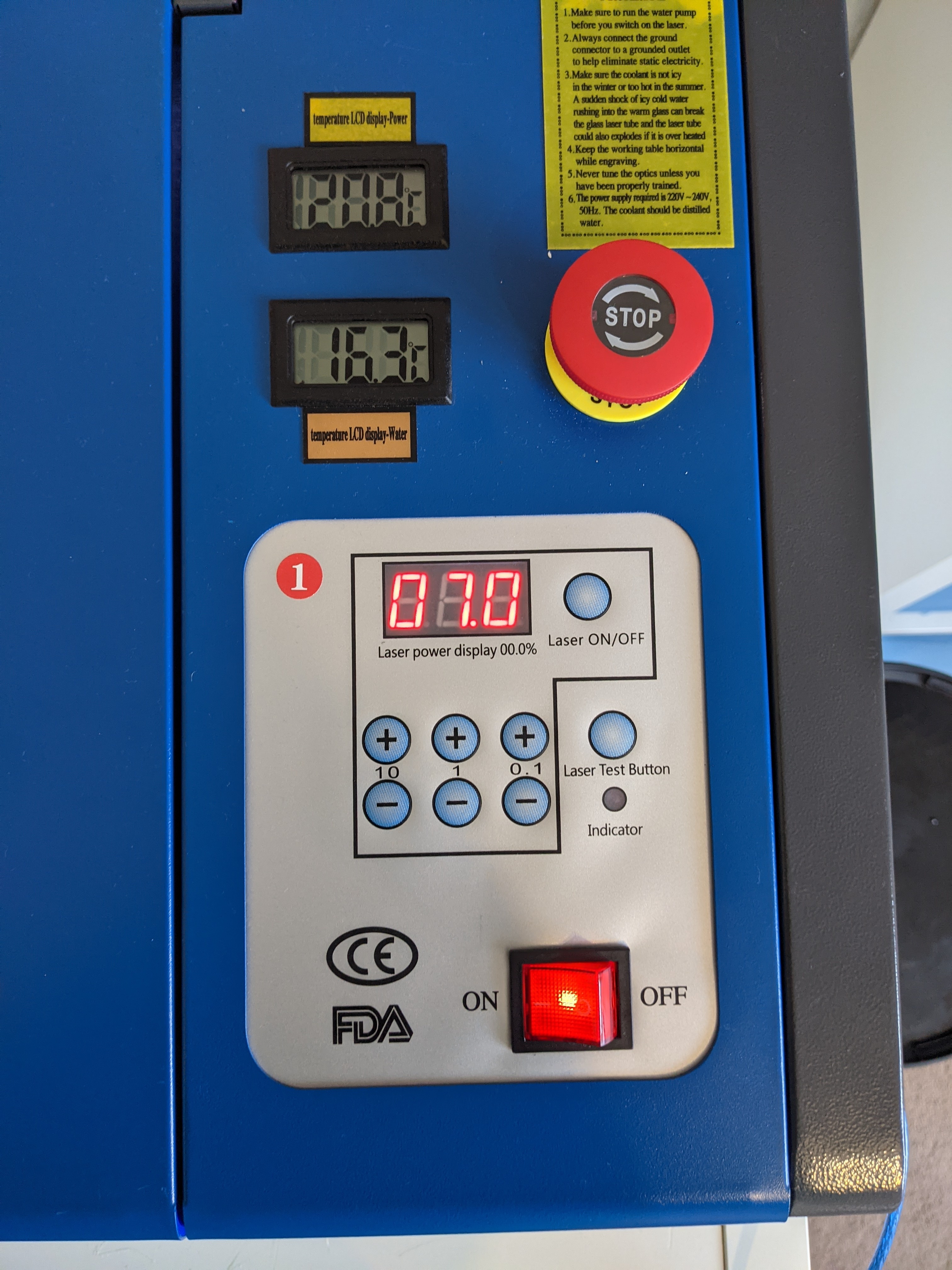

The digital meter doesn’t measure power at all, and how the numbers it shows relate to current flowing through the tube can be different not only from one machine to another, but also can change over the lifetime of the tube. An analog meter is very inexpensive, just a few dollars.
It’s sad that manufacturers persist on selling units without them, often even representing “digital” as better. ![]()
For mirror 3, what you really want to do is make sure that the beam is centered in the nozzle. You can remove the nozzle, put tape on the bottom of the down tube under mirror 3, and shoot a test. Mark the edges of the tube on the tape so you can see whether the beam is centered when you remove the tape to look at it. Ultimately you want the beam centered in the middle of the tube regardless of the position of the laser head. If the beam isn’t centered in the nozzle, it will be bouncing off the edges of the nozzle opening and will make quite the mess.
Your test shots do demonstrate that the mirrors aren’t yet aligned. This confirms the most likely diagnosis!
If this process ends up being super frustrating, do consider the visible laser backwards alignment tool I linked in my post. Being able to see the beam can make this a less frustrating process…
Thank you - will try the tape under the laser head now … I’ve had a little weird thing happen tho - I’ve aligned mirror 1 + 2 (to the Y axis and mirrors, both make fits into of each other) but when I fire to mirror 3 on position 2 (top right corner) it’s making a double dot? Is this reflecting off the rim of the lens opening? Thanks again for helping! X
Stopped the double dot - but now the cut has a haze around it! I’ve ordered sone new lenses which should arrive tomorrow - I think I may need to raise the laser up a little because after I aligned mirror 1+2, mirror 3 dot was nearly at the top rim! The dot under the laser head was centred - abit confused about what’s happening tho! I hope I can figure it out eventually!
Glad you’re working out your alignment issues but you should not be running the laser at more than 40% on the digitial setting without knowing what the real power level is. I’ve seen people burn out their laser tube in less than a year thinking they were only running at less than full power when anything over 45% on their machine was 24mA.
Please read through all of the K40 Intro at the top of this page, one section specifically mentioned not setting the digital power meter over 40-50% because it can over drive your laser tube. In the Don’t section here:
That’s really good to know - I’m hoping to run it at the lowest power possible that achieves a nice cut etc, but right now not even full power cuts 3mm balsa wood I’ve ordered some new lenses and laser head with built in air assist … will try again tomorrow!
Until you install an analog milli-ampere meter or directly measure with a multi-meter, it is highly recommended you set the power level to the minimum possible to do your mirror testing and lens calibrations( ramp testing ). Remember, setting that digital display to anything over 40% is likely over driving the laser power supply and the laser tube and these cheap laser cutters are not designed to last long when that is done. Hence the many recommendations to use an analog meter and never drive the machine over 18mA(this would be your 100% level ).
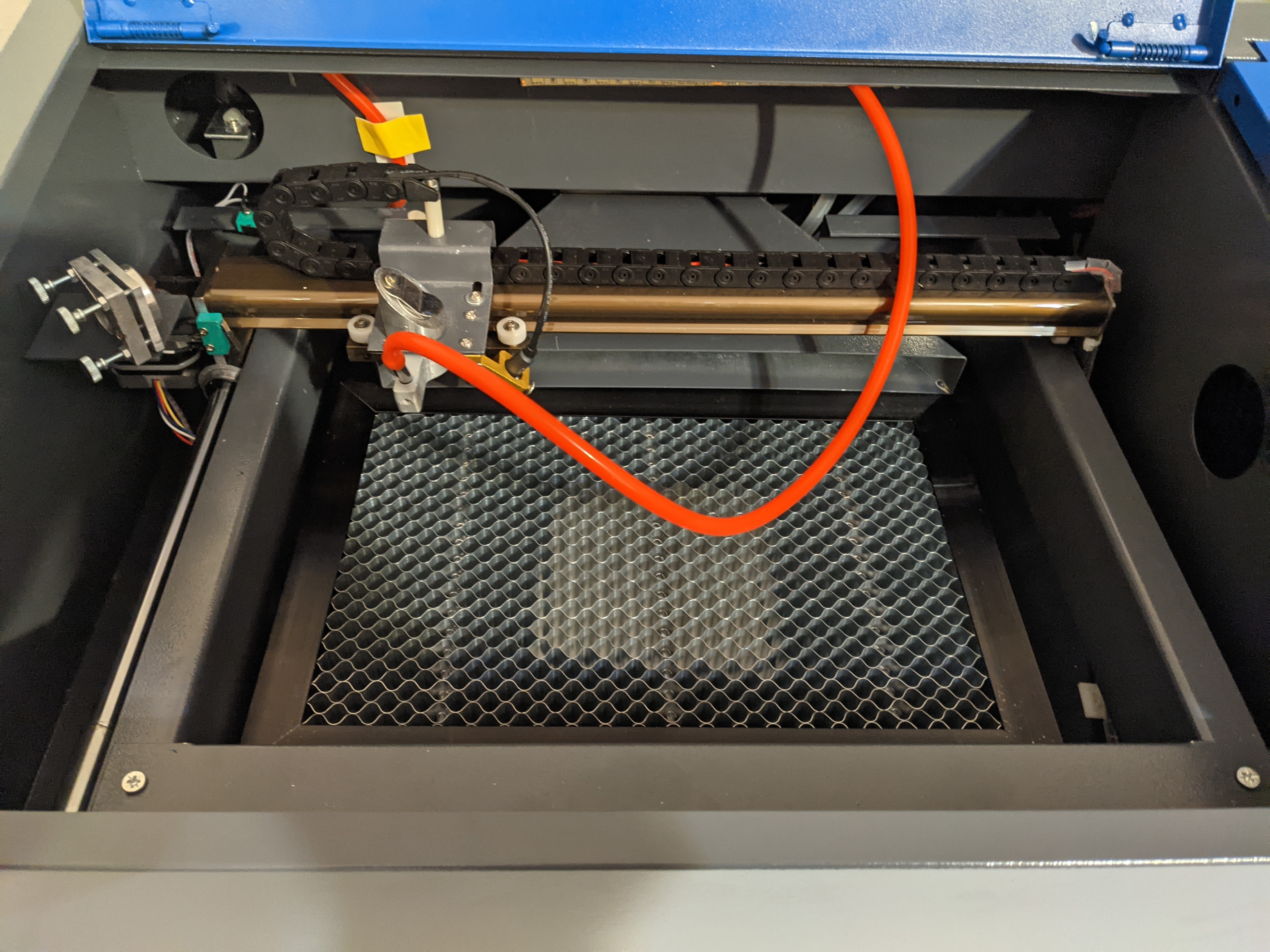
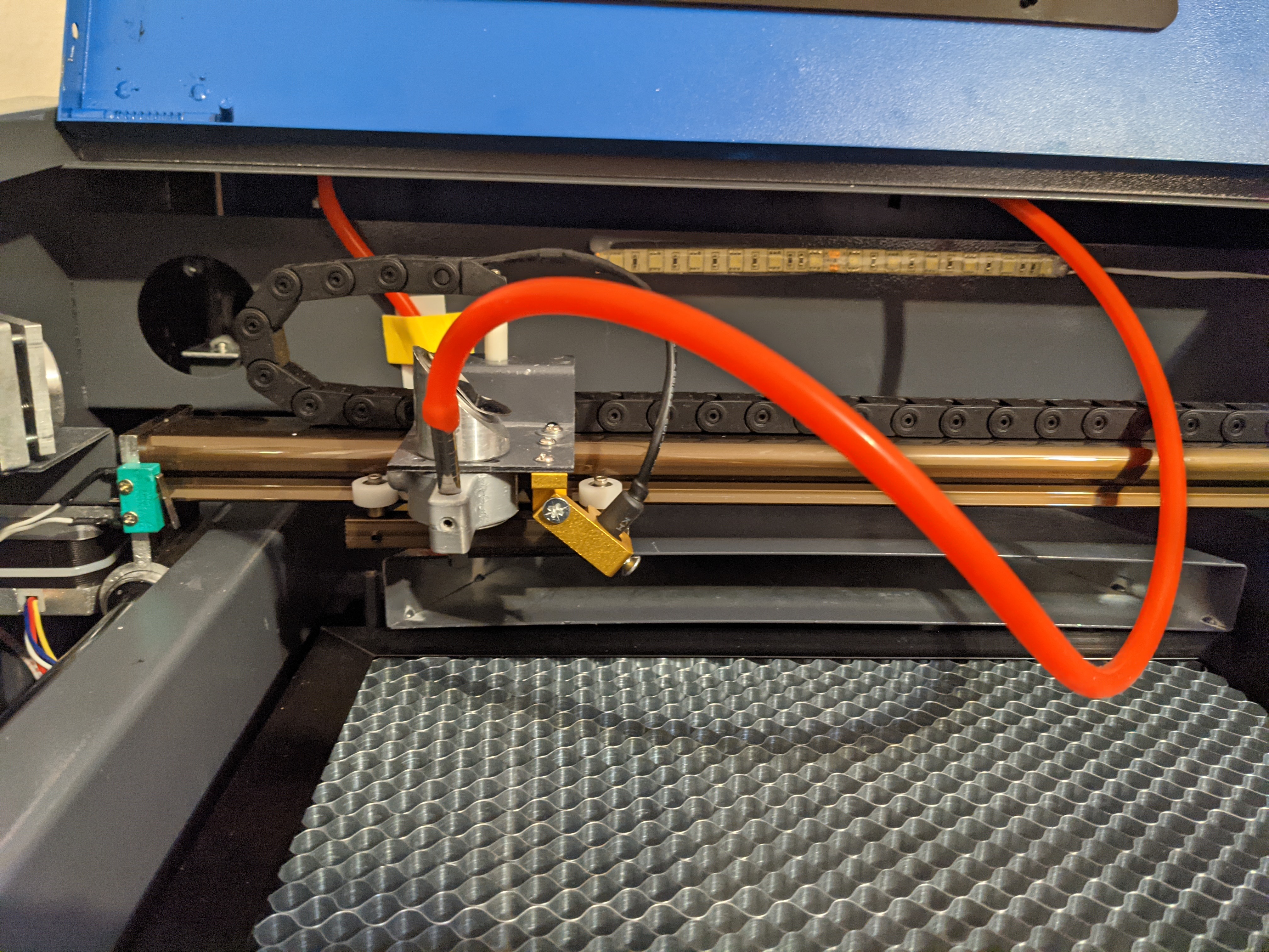
As for getting new parts, if it is a new machine you should not need new parts at this stage and although your pictures are from above, it looks like it already has air assist. Can you provide a couple of pictures of your laser head from the side so we can see what you are working with?
Once you know you are getting a single dot through all mirrors and out the laser head lens the very next thing to do is a ramp test so that you know where the focus point is. This test will also expose other problems regarding the lens like if it is installed upside down. You should not need new parts until you know there is something needing to be replaced.
One more thing, I see you are using tape in front of your mirrors to determine the laser alignment and while you will find people saying to use tape, do not use tape unless you put something behind it so that any burn-through does not splatter molten glue onto your mirrors. Far better to use paper which has no glue on the back and at worst will put a little ash on the mirror which could be blown off with compressed air.
The other thing I noticed was the markings on the tape shown in the pictures are not burning through the tape. Is this because you have lowered the power level to the point it only marks or are you still setting the output to 80% or so?
I’ll definitely do post-its next time - I was a little worried about the scorch tests dirtying the lenses so I got a little acetone on a cotton bud to clean them - is this ok to use?
Yes, in a little cautious using high power, so lowered it to 7% - I have to hold for 5/6 seconds to get a burn mark in the far right if the laser - is this normal?
Decided to try and fit an Amp meter and a safety switch to the lid - do you know of any good video instructions for this? I have no electronics experience and really feel the fear when dealing with high voltage like this!
Thanks again for the help x
I have not looked at lots of detailed instructions on installing the milli-amp meter so maybe someone else on this forum has familiarity with which one is best for someone without any electronics/electricity skills. Simply put, it’s a matter of removing the RETURN wire from the laser power supply, connecting it to one side of the mA meter then add a wire to the other side of the mA meter and connect it back to the laser power supply where the original wire was connected. IIRC the marking on the power supply is “L-” but the instructions should show and describe it better.
Good job lowering the output power to just mark the tape. And yes you can use acetone to clean them mirrors with a swap but be advised, the technique is to gently move the swap while rotating it one turn, repeat with the cotton swap at the other end of the Q-tip(they have 2 tips) then throw it away and use another. You don’t want to cause friction/rubbing on the mirror using particles removed from the mirror. Yes it can take up lots of cotton swaps to clean a mirror.
Great thank you for the tips on cleaning the mirrors - mirror 2 was pretty grimey! And for the Amp meter info, will get my hubby to help with that, he’s computer savvy but not electrical (if that makes sense!) but hopefully between us we can do it safely 

I am a little disheartened tonight, really want to get it working properly and finally make something nice! I was aligning the mirrors for a good couple of hours but it seems like they’re worse now! Mirror 1+2 are aligned but having real issues with mirror 3 - I can’t get the dots to sit on top of each other in all 4 corners of the laser bed - I’ll have to do some more research
Thanks so much again, all this help and Information has been amazing xx