Thanks Don,
I think it was pulling 5V from the USB cable. I noticed the usb cable getting hot one time.
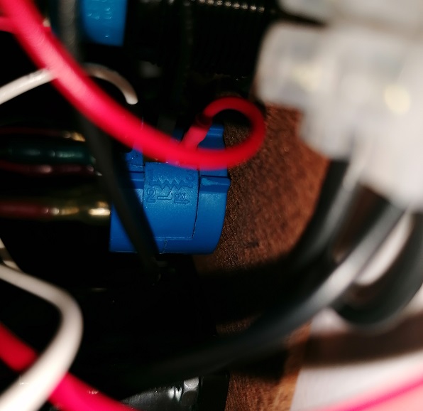
I was confused, this wire goes to the red dot laser module.
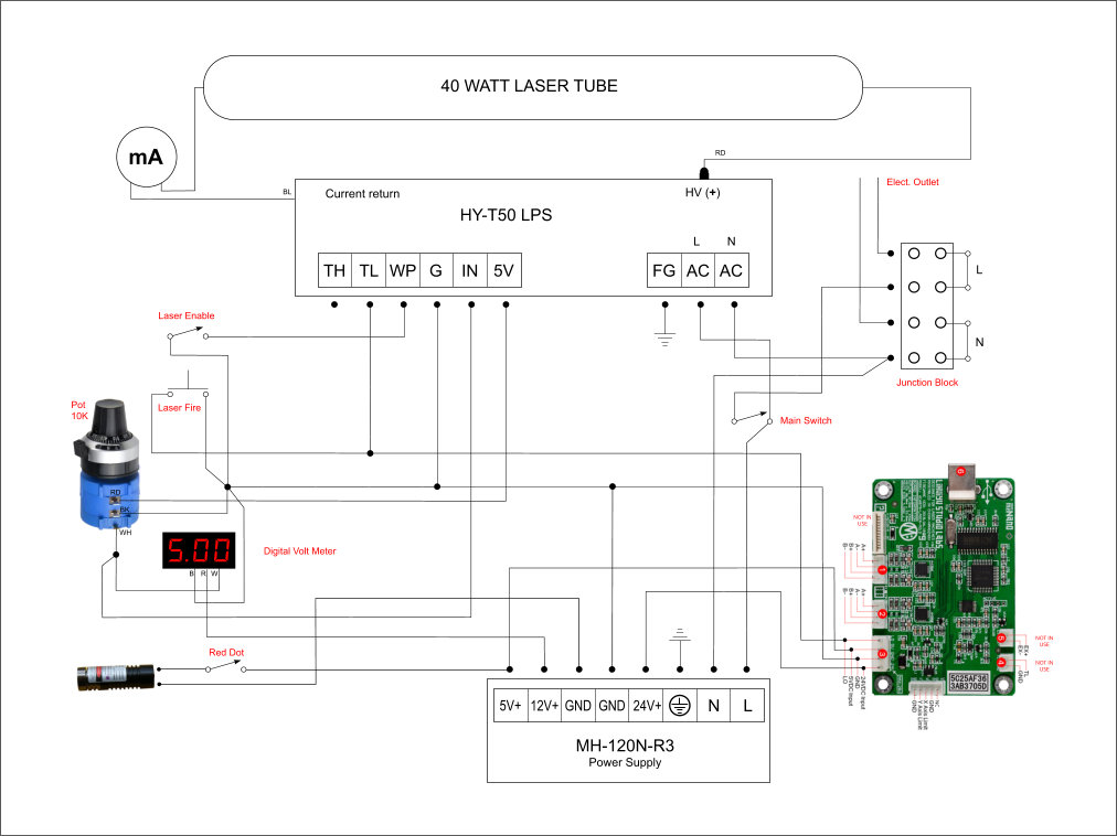
Here is the new diagram. What do you think?
Thanks Don,
I think it was pulling 5V from the USB cable. I noticed the usb cable getting hot one time.
I was confused, this wire goes to the red dot laser module.
Here is the new diagram. What do you think?
That updated diagram looks good.
I don’t know what exact parts the pot and laser pointer are so:
After the DC supply is wired in I recommend testing all the outputs before you hook anything to it.
Then hook up each load in turn (least critical items first) and test them, with the last being the controller.
After everything is wired and the voltage for each termination is measured fill out the table and we will verify that everything looks normal.
Note: for the “IN” measurement put the pot approximately in the middle of its travel.
To Fill in the table:
If you highlight the table in this post
Then click “quote”
A post will open with the tables formatting in place
Just change the values of the “x’s” to your measured values
I note that in the diagram above it is connected to 5V and 5V is at least a common voltage for the red dot lasers, which also often run off two or three button cells. So it’s at least reasonable for it to be 5V.
Your right (and well said btw). I was thinking that mine is 12V and wondered if that one was also.
I ordered one yesterday, thanks!
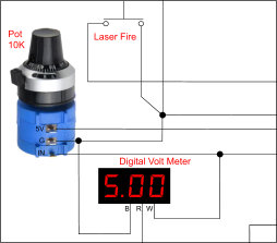
I tried switching the wires from the POT, but its not reading right.
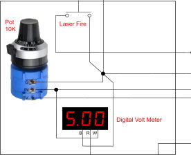
This is the POT I’m using.
Having the POT wired this way I start at 0 volts and by turning the knob clockwise i can go all the way to 5 volts.
Why did you change the pot wiring?
I was just warning you that I remembered the wiring to be strange…
As long as the IN pin reads 0-5V when the pot it turned clockwise you are good.
Ok, I’m gonna leave it like it was.
I found a PSU from an old PC, I’m gonna try to pull 5 and 12 volts to power the Nano and some accessories and do the testings while the new PSU arrives.
I don’t know if you know this and I am not sure I remember it right but:
You have to have a min load on these PC power supplies for them to regulate correctly.
I had a gaggle of problems using these PC supplies until I found this out.
This may not be an issue since you are running the Nano using the 5V rail but thought I would mention it in case it acted weird 
https://www.electronics-tutorials.ws/blog/convert-atx-psu-to-bench-supply.html
Note: A 9 Watt load resistor is included but not soldered to the board. In our experience most modern ATX supplies don’t require a significant load on the 5 volt rail to start. An artificial load just wastes electricity and creates unnecessary heat. Please let us know your experience.
I have one of these attached to a Thermaltake ATX PSU, and I didn’t solder in the load resistor. I didn’t see poor regulation on 5V. I now have two bench power supplies so I haven’t used the PSU breakout for a long time.
Something to keep in mind. You may not see or recognize poor regulation unless you load the supply. How much load, I don’t know.
I used 5V with one 'scope channel on it several times, so not having noticed artifacts, my particular power supply was probably adequate without a dummy load.
Thank you both four your comments and links. I will keep that in mind!
I will be doing some test tonight. I’m keeping my fingers crossed.
Hello Don, the K40 came back to life with the PC power supply (I’m still waiting on the one you recommended from amazon).
Having separate power supplies makes a big difference. It feels like it has more power.
You asked me to check the Gnd voltage on the Nano board, but I’m not sure how to do that.
My problem was the 20ma coming from the 5v (50 watts LPS) like you mentioned. I was not supposed to power anything else, just the POT. Can’t wait for the new dual PS to arrive!
I still need to send you all the voltages!
Hello Don!
These are the voltages using the temporary PC PS, missing the G and Gnd.
Was the Laser enable sw on when you measured these voltages.
I am just wondering why WP is 0V.
The rest of these voltages seem reasonable.
Did you try running the machine with this setup?
Yes, it was. The voltage with the laser not enable on SW was 4.96v.
Does that sound normal?
I did try running the machine and it feels way better than when I first got it.
I should be getting my dual PS this week.
Yup that sounds normal.
Thank you Don and Michael for sharing your knowledge.
It helped me out a lot 
I should have done this earlier, but better late than never, and now especially since another user has run into this problem…
I just added a warning that 5V on the HY-T50 is only a reference voltage, not a power supply, to the K40 replacement parts article: