Oh my, Sorry, I did not notice that you had no 5V power to the nano.
I don’t know how this worked at all?
After you made the upgrades:
Did the Nano connect via USB?
Did your carriage move at all?
When I drew the conversion diagram above we did not know the 5V capacity for this style LPS. Most of these use a LM7805 which can source 1A, we assumed that was the capacity.
I seriously doubt 20ma is enough to run the Nano properly.
These are the changes I recommend:
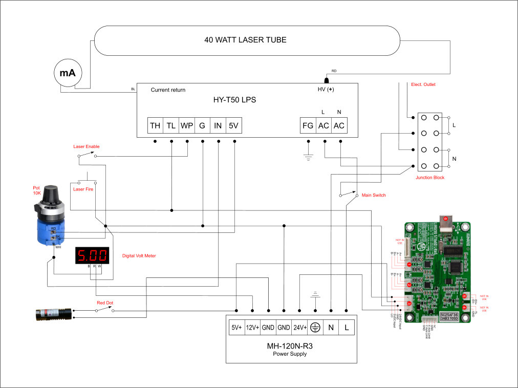
Insure all grounds are connected together including: 24V, 5V*, 12V*, LPS, Nano. [*if installed]
Add a 5V supply for the Nano. I would go for 3-5Amps. 1A is the stock supply source for the nano. Insure its ground is connected to the other grounds.
You can use one of these approaches:
Add a 5V buck converter to the 24V. There are many choices on amazon. Something like: https://amzn.to/3bMtvCa. I generally don’t like buck converters on logic boards because if they aren’t good designs they are noisy. It also depends on the capacity of your 24V supply? They really aren’t that much cheaper anyway. $12.5
Add a separate 5V supply: Lots of choices on amazon like this one: https://amzn.to/38P5QPq $12.5
Add a dual supply: Again, lots of choices on Amazon. This is a reputable supply maker and you get all three voltages 5,12,24 in the same supply. I use 12V alot for accessories. Amazon.com $23
Other questions:
Where does the wire (TO STEPPER MOTORS) go. Its at the bottom of your diagram and comes from -24V.
Next steps:
I would suggest amending your diagram adding your choice of 5V supply and then post here to review it before you purchase.
Purchase power supply
Install power supply and check wiring
After installation we should do DC measurements to verify the install.
Do you have a DVM and do you know how to operate it?
When you are done making the changes power up and please complete the table below.
Measure all these voltages with the ground lead of the meter on the same ground point.
Meter set to measure DC volts.
Location
Terminal
Voltage
24VPS
+24V
xx
Nano
5v
xx
Nano
24V
xx
Nano
Gnd
xx
LPS
TH
xx
LPS
TL
xx
LPS
WP
xx
LPS
G
xx
LPS
IN
xx
LPS
5V
xx
To Fill in the table:
If you highlight the table in this post
Then click “quote”
A post will open with the tables formatting in place
Just change the values of the “x’s” to your measured values
As an Amazon Associate I earn from qualifying purchases
I don’t know what exact parts the pot and laser pointer are so:
I assume the laser dot takes 12V
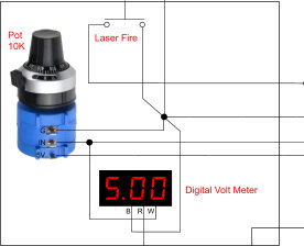
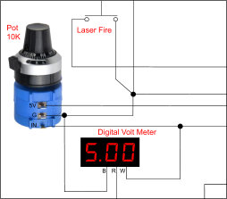
I assume the pot is correctly wired. I know the pot type pictured in the diagram has a wiper in an unusual place but it is usually marked on its side.
After the DC supply is wired in I recommend testing all the outputs before you hook anything to it.
Then hook up each load in turn (least critical items first) and test them, with the last being the controller.
After everything is wired and the voltage for each termination is measured fill out the table and we will verify that everything looks normal.
Note: for the “IN” measurement put the pot approximately in the middle of its travel.
To Fill in the table:
If you highlight the table in this post
Then click “quote”
A post will open with the tables formatting in place
Just change the values of the “x’s” to your measured values
I note that in the diagram above it is connected to 5V and 5V is at least a common voltage for the red dot lasers, which also often run off two or three button cells. So it’s at least reasonable for it to be 5V.
Ok, I’m gonna leave it like it was.
I found a PSU from an old PC, I’m gonna try to pull 5 and 12 volts to power the Nano and some accessories and do the testings while the new PSU arrives.
I don’t know if you know this and I am not sure I remember it right but:
You have to have a min load on these PC power supplies for them to regulate correctly.
I had a gaggle of problems using these PC supplies until I found this out.
This may not be an issue since you are running the Nano using the 5V rail but thought I would mention it in case it acted weird
Note: A 9 Watt load resistor is included but not soldered to the board. In our experience most modern ATX supplies don’t require a significant load on the 5 volt rail to start. An artificial load just wastes electricity and creates unnecessary heat. Please let us know your experience.
I have one of these attached to a Thermaltake ATX PSU, and I didn’t solder in the load resistor. I didn’t see poor regulation on 5V. I now have two bench power supplies so I haven’t used the PSU breakout for a long time.
I used 5V with one 'scope channel on it several times, so not having noticed artifacts, my particular power supply was probably adequate without a dummy load.
Hello Don, the K40 came back to life with the PC power supply (I’m still waiting on the one you recommended from amazon).
Having separate power supplies makes a big difference. It feels like it has more power.
You asked me to check the Gnd voltage on the Nano board, but I’m not sure how to do that.
My problem was the 20ma coming from the 5v (50 watts LPS) like you mentioned. I was not supposed to power anything else, just the POT. Can’t wait for the new dual PS to arrive!
I still need to send you all the voltages!
Yes, it was. The voltage with the laser not enable on SW was 4.96v.
Does that sound normal?
I did try running the machine and it feels way better than when I first got it.
I should be getting my dual PS this week.