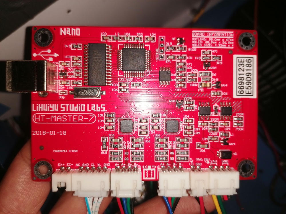
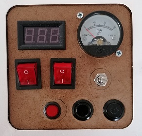
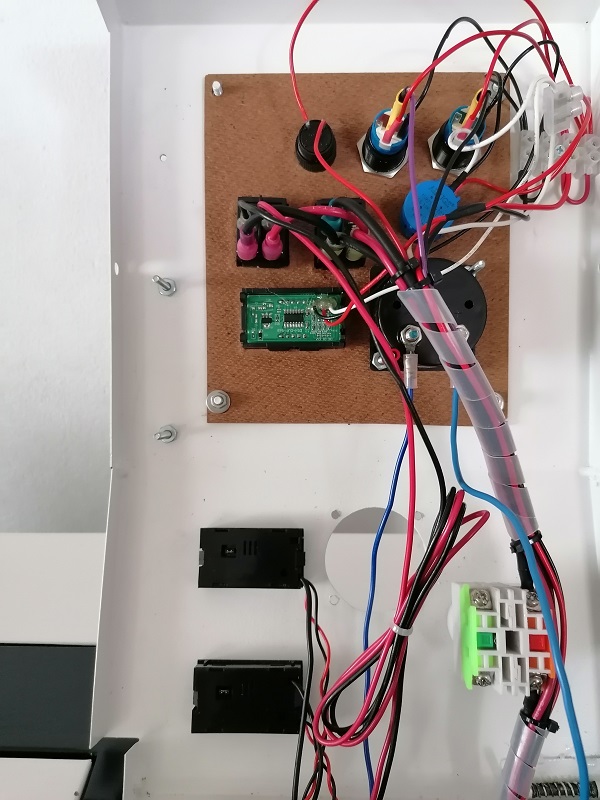
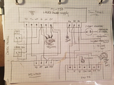
Hello guys, I recently had a tube failure on my FL-K40D and decided to change a whole bunch of parts (Power supply, nano board, laser tube, new analog panel, switches, pot, digital volt meter, amp meter, mirrors, etc.).
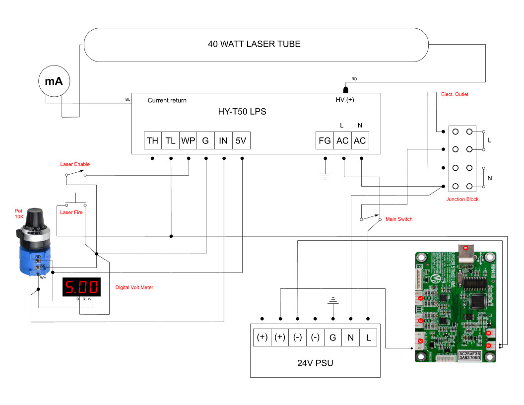
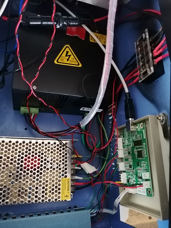
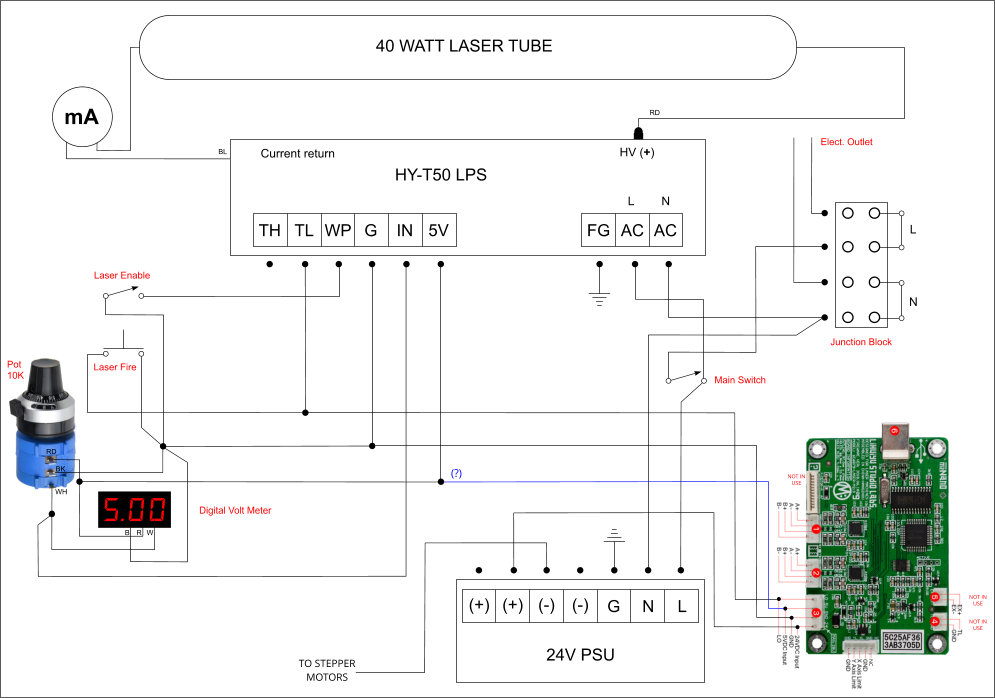
I made this wiring diagram by looking and searching on the web. When I try to raster engrave on rubber, the laser doesn’t seem to have enough power. It barely touched the material (Pot was set to 10ma manually). Not sure what I’m doing wrong.
Any help is going to be appreciated. 
Hello Don, thanks for all the knowledge you are sharing.
I tried doing my own wiring, but something its wrong. I can set the desire power manually by adjusting the pot, but when i sent the command on the K40 whisperer to raster engrave, I do not get enough laser power on the material.
(Tube, LPS, PSU, Pot, Switches, M2 Nano board, Laser Tube, Digital Voltmeter are brand new).
1 Like
I will take a look. Nice drawing BTW.
While I am looking at your schematic let’s cover some basics;
- Does you laser fire (light in the tube) during the engraving?
- What does your mA read when engraving?
- Does the laser engrave on materials other than rubber?
- Have you done an optical alignment?
Please attach the associated question number to your answers.
1 Like
Hello Don, thanks for replying.
1- Yes it does fire, but seems to have low power. (Replaced the tube twice, thinking it was bad).
2- Stays between 2 and 3 ma.
3- Yes, i usually engrave rubber, wood and acrylic.
4- Yes, twice for every tube I replaced.
Wonder if I should use your diagram instead?
I don’t see anything obvious wrong with your diagram.
Since your machine is engraving but at too low of power I would assume:
- the controller wiring is good
If the problem is not optical
1 Like
2.1 I can adjust the pot to higher power, but when I start using the K40 whisperer software I am not able to increase the power while is engraving. Power stays low (It puts a thin carbon film on the rubber sheet without depth)
3.1 Does not engrave properly on any material right now.
5.1 Sorry, I meant your drawing. I am not as know knowledgeable as you are (I would have to integrate the digital volmeter display on your schematic), I would like to try your schematic.
6 Yes, it dit for almost 2 years. It was my only means of creating an income with this pandemic until last month. Thats why I am so desperate.
I used to have this other board (Had the same problem though).
My thinking:
- If the engraved image is correctly formed the low power problem is not in the controller or its wiring such as the TL connection.
- If the laser fires during a job it’s not likely basic laser control circuits like WP.
If everything images correctly but it is just low on power. Here are typical problems:
- The voltage on IN is not as expected (this should show on your digital meter)
- There is an optical alignment problem
- Beam not in the center of mirrors
- The beam enters/exits mirror 3 in the head at an angle, causing it to hit the side of the enclosure before it exits and attenuates power.
Possible but not likely
- Low laser power (you already replaced 2)
- Bad LPS (the laser current is ok and the laser fires)
- Run an engraving job on wood (or something that doesn’t take much power to engrave on) and post a picture just so we how it engraves.
- For that same job show a picture of the control panel settings especially the digital meter.
I had a bad m2Nano board that caused low power output.
1 Like
That’s interesting, the stock board does not PWM it just dithers right?
I wonder if there is a problem with where he is getting the L signal from? Note not on the typical power connector?
This is what I used to be able to engrave and cut before I started loosing laser power and decided to buy a new tube and do too many upgrades at once (Bad idea). Never liked the digital panel, I wanted to have better control with an analog, but I am not an expert when it comes to electronics.
I’m gonna follow your recommendations and post the results.

I purchased two M2 Nano boards from Cloudray just in case. The board that came with my K40 was a weird model. Thanks for the comment.
Yes, the stock M2 Nano only dithers.
When I saw your schematic I started wondering too.
I’m thinking about rewiring and use your schematic instead. What do you suggest?
I’d suggest starting with this previous suggestion:
Thanks, I will do that first!
Action #1: Please post or link to my schematic you refer to.
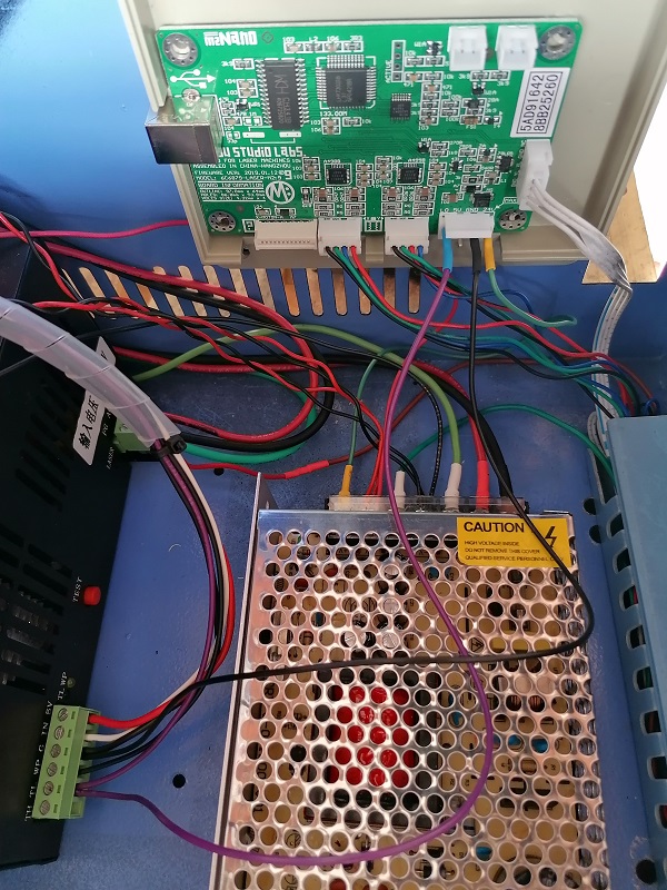
Action #2: Then I would change this wiring (picture attached):
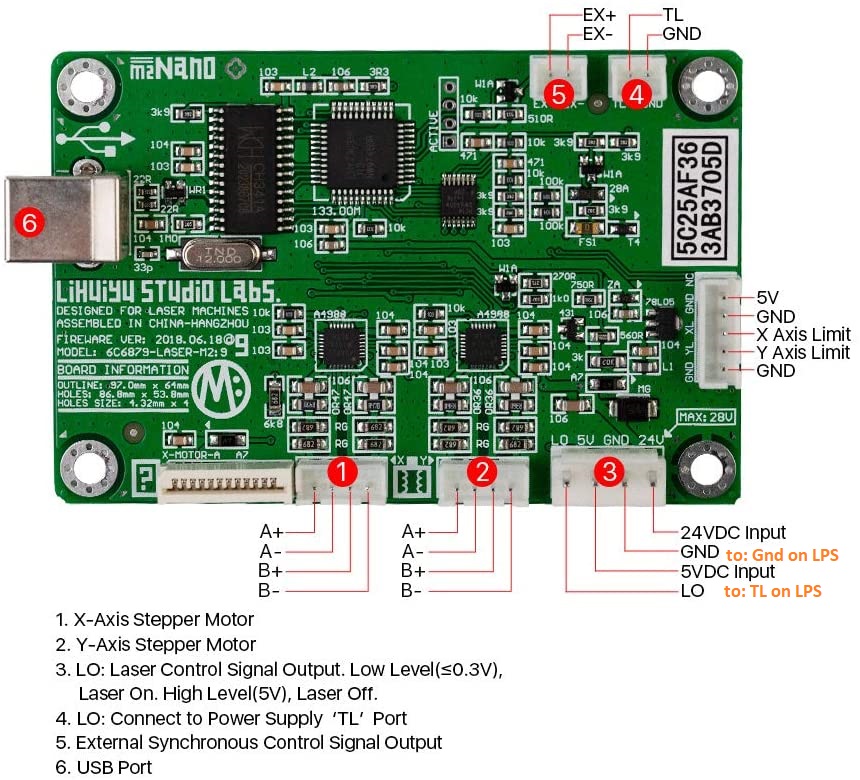
- Move the LPS-TL to the M2Nano-LO on connector #3 in the drawing
- Connect LPS-Grnd to M2Nan-GND on connector #3
The above wiring changes are mostly to insure consistency with my experience.
Action #3: Test and see if the changes completed in Action #2 made any difference.
- If not continue to Action #4.
Action #4: Test the LPS static power control
- Connect a DVM between LPS-IN and LPS-gnd and set DVM to measure DC Volts
- Turn the pot to the pot-value of column 1 in the table
- With Enable Switch ON Test Fire the Laser long enough to get a stable reading on the ma meter.
- Record values in the table below
| Pot-volts | IN | Lma |
|---|---|---|
| 1 | xx | xx |
| 2 | xx | xx |
| 3 | xx | xx |
| 4 | xx | xx |
| 5 | xx | xx |
Pot-volts: this is value on the digital voltmeter on the panel
IN: this is the DC voltage on the LPS-IN pin
Lma: the value on the analog laser current meter on the panel in ma
To Fill in the table:
If you highlight the table above while reading this post
Then click “quote”
A reply post will open with the tables formatting in place
Don’t mess with the formating (|), just change the x’s to your measured values

Hello Don, This is the schematic I was referring to.
I moved the TL and Grnd connections.
I tried to do a test, but the computer was not recognizing my K40 (Tried different usb ports, replaced the Nano board with the other one I bought, but same results).

Do I need to send 5V from LPS to connector #3?
I’m stuck on action #2.
What do you think I should do?
The 5V supply is what powers the processor on the board as well as the limit switches. The 24V powers the stepper motors only. If you don’t supply 5V, it won’t function.
Thanks Michael!
I was wondering:
Is it safe to pull 5V from LPS to power the board and the digital voltmeter?
Do I need a (-) connection from 24V PSU to GND on Nano board also?

Oh my, Sorry, I did not notice that you had no 5V power to the nano.
I don’t know how this worked at all?
After you made the upgrades:
- Did the Nano connect via USB?
- Did your carriage move at all?
When I drew the conversion diagram above we did not know the 5V capacity for this style LPS. Most of these use a LM7805 which can source 1A, we assumed that was the capacity.
I looked around again and this time found a spec: 5V@ 20MA
https://www.amazon.com/Engraving-Cutting-Temperature-Relative-Humidity/dp/B08PD941Q9/ref=sr_1_6?dchild=1&keywords=Hy-T50&qid=1610720450&sr=8-6
It may be that my original drawing was flawed, or at best marginal. I am pretty sure it worked but I would not chance it. Poor supply capacity can cause a myriad of headaches.
I seriously doubt 20ma is enough to run the Nano properly.
These are the changes I recommend:
-
Insure all grounds are connected together including: 24V, 5V*, 12V*, LPS, Nano. [*if installed]
-
Add a 5V supply for the Nano. I would go for 3-5Amps. 1A is the stock supply source for the nano. Insure its ground is connected to the other grounds.
-
You can use one of these approaches:
-
Add a 5V buck converter to the 24V. There are many choices on amazon. Something like: https://amzn.to/3bMtvCa. I generally don’t like buck converters on logic boards because if they aren’t good designs they are noisy. It also depends on the capacity of your 24V supply? They really aren’t that much cheaper anyway. $12.5
-
Add a separate 5V supply: Lots of choices on amazon like this one: https://amzn.to/38P5QPq $12.5
-
Add a dual supply: Again, lots of choices on Amazon. This is a reputable supply maker and you get all three voltages 5,12,24 in the same supply. I use 12V alot for accessories. Amazon.com $23
-
-
Other questions:
Where does the wire (TO STEPPER MOTORS) go. Its at the bottom of your diagram and comes from -24V.
Next steps:
- I would suggest amending your diagram adding your choice of 5V supply and then post here to review it before you purchase.
- Purchase power supply
- Install power supply and check wiring
- After installation we should do DC measurements to verify the install.
- Do you have a DVM and do you know how to operate it?
When you are done making the changes power up and please complete the table below.
Measure all these voltages with the ground lead of the meter on the same ground point.
Meter set to measure DC volts.
| Location | Terminal | Voltage |
|---|---|---|
| 24VPS | +24V | xx |
| Nano | 5v | xx |
| Nano | 24V | xx |
| Nano | Gnd | xx |
| LPS | TH | xx |
| LPS | TL | xx |
| LPS | WP | xx |
| LPS | G | xx |
| LPS | IN | xx |
| LPS | 5V | xx |
To Fill in the table:
If you highlight the table in this post
Then click “quote”
A post will open with the tables formatting in place
Just change the values of the “x’s” to your measured values
As an Amazon Associate I earn from qualifying purchases
1 Like