I’m hoping someone can help me here. The issue is that I don’t understand anything about electricity, but I can follow pictures and diagrams.
I needed to purchase a new laser tube for my K40, and I decided not to upgrade to a 50W tube. Therefore, I bought a new 50W tube and a 50W power supply from Cloudray. Before ordering, I contacted Cloudray customer support to inquire whether my machine with the Nano2 motherboard would be compatible with this type of upgrade. I was informed that it would be compatible.
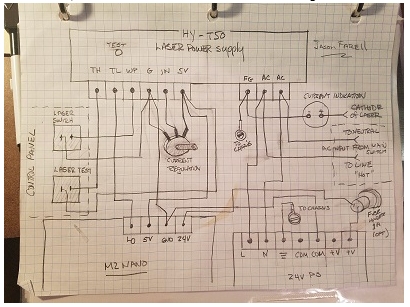
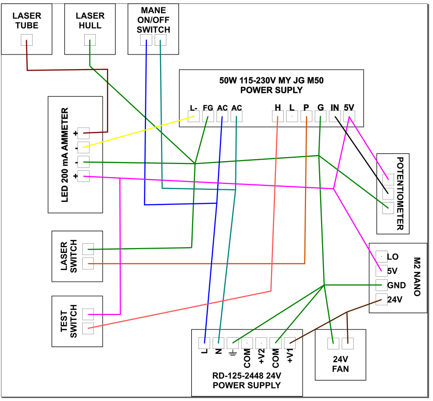
When the new parts arrived, everything was fine until it was time to start the electronics. The new power supply had fewer connections than the old one. After conducting some research online, I discovered that I needed an additional 24V power supply. I also found a picture of a diagram that appeared very similar to my situation.
After completing the necessary adjustments, the machine turned on and connected to my PC. The third mirror moved with the 40k whisperer controls, but the laser itself did not turn on. Neither switch was working, the LED ammeter was showing nothing, and the potentiometer was not functioning.
Is there a way to fix this issue with my current setup, or do I need to purchase a new motherboard?
It does not fire.
I have no clue about the connection between Nanno and LPS. I have 0 understanding of electronics. It would be great if you could explain me as simply as possible or with drawings.
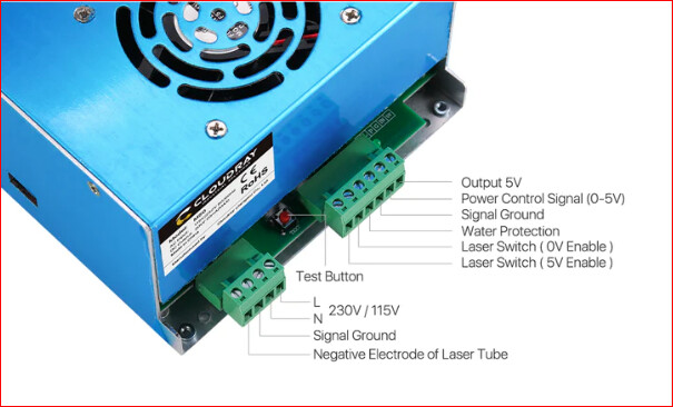
The LPS should fire with the test switch irrespective of any other of the connections except the pot.
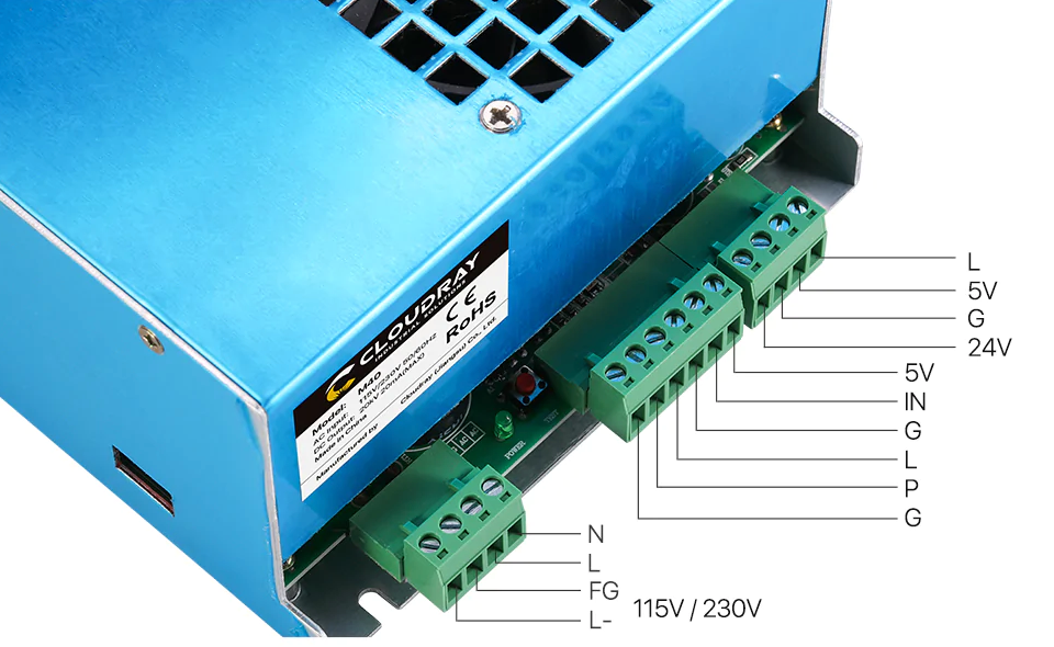
Your LPS picture does not reflect the LPS that is in your drawing??
Do you have this one?
Verify the LPS has AC mains power.
Verify that the voltage switch (on the left side if there is one) is in the right position for your mains power voltage.
There should be an LED down on the board near the connectors it could be red or green. It may be labeled, “Power”. When the machine is powered on does it illuminate?
You will note in the “diagram you found” there is a connection between M2 Nano-LO and the LPS-TL. TL = Laser Switch (0V Enable) OR L on your supply.
Yes, That is LPS that I have. The left side switch is in the correct position, LED down on the board is green. And between LPS- L and Nanno- L0 is a connection.
the voltage between the G and P is ~4,66V
the voltage between G and IN is ~4,66V
With the pot turned all the way counterclockwise, I got ~0V.
As I turn the pot clockwise, the voltage gradually increases until ~4,66V
And still no laser action.
Let’s review so I don’t take us on a wild goose chase:
With power on and the voltage switch in the correct position:
The LED on the board is illuminated
With the LPS wired as shown in the schematic [with the addition of the LO wire]:
The laser does not fire when the red LPS test button is pushed
With all wires disconnected except the POT
AND The pot is positioned at max.
The laser does not fire when the red LPS test button is pushed
With all wires disconnected except the POT and reading with a DVM
The IN voltage = 4.6 V when pot is max
The IN voltage = 0 V when pot is min
Also to verify:
The LPS is a new 50w supply.
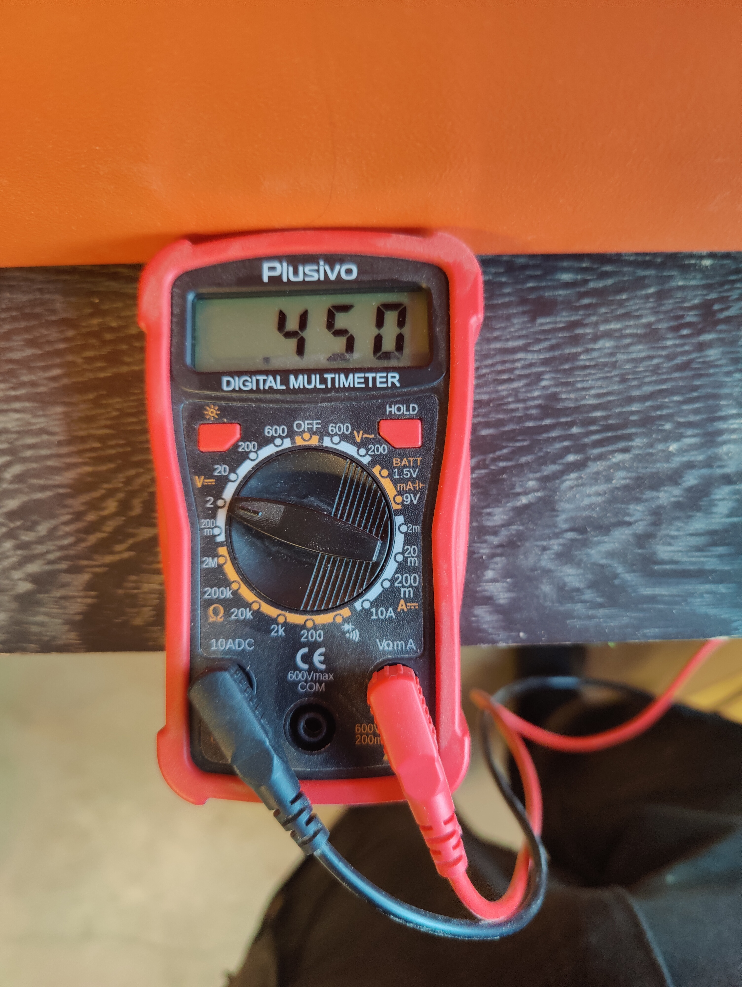
Meter reading:
I am surprised by the meter’s display.
On the 2v scale, it reads .466. I would expect the decimal place to be one more to the right or the meter to max out if the voltage is 4.6V. Perhaps the voltage is really .46? 4.6V is abnormally low.
I am just verifying that the meter and our measurements are correct by measuring a known point.
--------------------- Reasoning ---------
If there is no 5V on the LPS [i.e. measured .4v], then the LPS supply is bad.
However, this is a new supply and that would be unusual.
In addition, the light on the LPS is on. That LED is connected to the 5V side of the LPS. Why is it on yet there is no 5V on the output pin?
Trying to make sure something is not fooling us into believing the LPS is bad.
Important: Make sure that nothing is connected to the 5V or any other output pin when you measure it.