@nickm324 are you able to post again?
The fan was connect to the bunch of wires from the main power from the socket, when I tested from the red wire coming from that group and normally connected to the power switch there was a short and there was nothing else connected but the fan, as soon as I cut the fan wires the short disappeared which lead me to think that the internal windings of the fan were shorted cause it to blow the fuses.
I have sent a message to the seller but they have not responded yet, probably cause its the weekend.
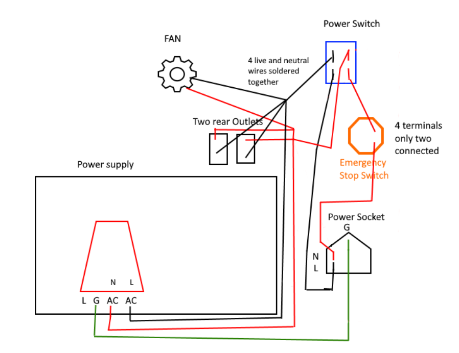
I will try and draw a diagram of how it was all wired originally and post it here maybe you will see something that could have been causing the problem.
Checking that we are on the same page:
When you say you tested the red wire and there was a short where did you measure the short?
When I say short I mean between the black (one side of the line) and the red (the other side of the line).
Have you been looking for shorts across L & N???
Yes, When I test the unswitched side (back power connection going to the soldered group of wires) to the red there was a short.
here is a crude drawing of exactly how my unit is wired. I have removed the fan connections and the two auxiliary outlets completely now.
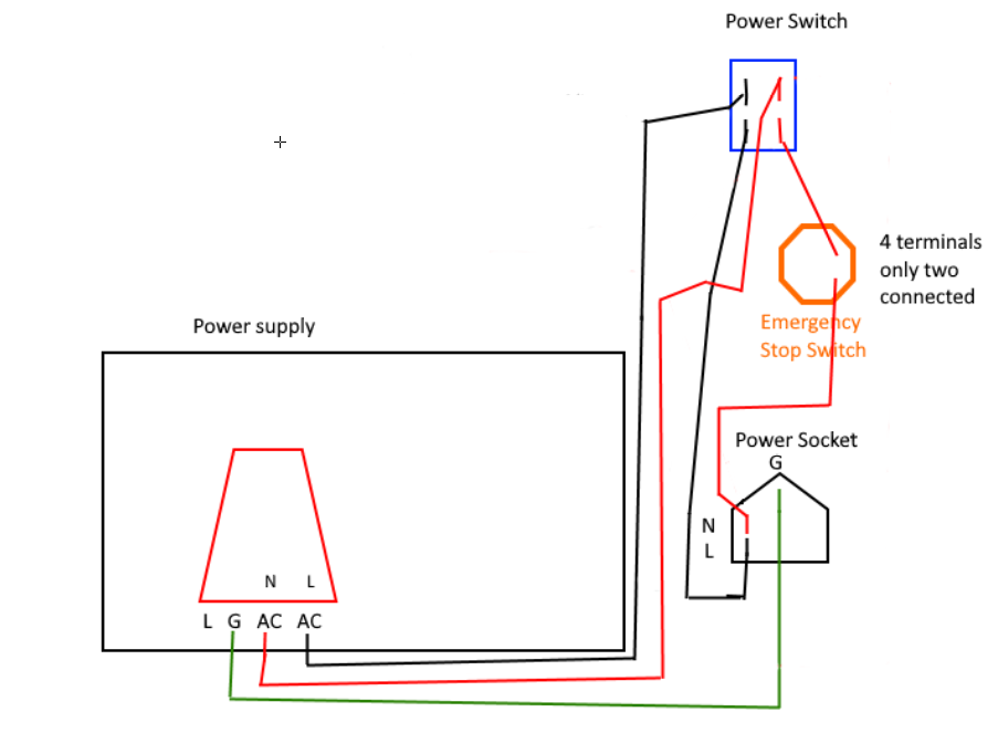
Ok exactly the same with the sockets and the fan missing.
I don’t see anything wrong with the before or after.
Where is the unit plugged in??
How do you know your house power is wired properly???
Do you have a socket tester?
Try putting a plug on the fan and see if it will run by itself.
The unit was plugged into that long black power strip I posted an image of last night. While dealing with these issues I had the water pump, the Cohesion3D power brick, 2 LED strip lights and the unit all plugged in at the same time. The water pump , Cohiesion3D board and strip lights all worked fine and still do. I can plug in the Cohesion board and move the X/Y on the gantry just fine, and the LCD on the panel for the Cohesion board displays correctly also.
I am in the US, my house was build in 2016 and requires to pass inspections at the end of construction and I have also since construction I had an certified electrician install additional wall outlets in my garage that I run my X-Carve CNC and many other things off of and is the same outlet I had the power strip plugged into. I am very confident that the grounding in my electrical is working correctly.
I will try and test the fan and see what happens but if it is shorted then its should trip a breaker before exploding like the LPS did, I hope.
If the original wiring looks correct then I can only assume that the LPS was bad from the start because the minute I plugged it in and hit the power switch for the very first time it blew the first fuse.
Still very suspicious, especially the relationship the fan has in the scenario?
The catastrophic nature of the failure bothers me as that usually means an input power problem.
I agree, I am still concerned with what caused the initial issue with the fuses blowing and then the power supply. Before I even put in the new LPS I am going to attach the power and measure for 110v at the switch terminals to ensure I have clean input from the house power source and then there is nothing left other than attaching the Neutral and Live to the two terminals on the LPS. Not really a whole lot that can go wrong in that simple circuit. I will post my results.
Of course there is always the possibility that some how I screwed something up when I was cutting wires and reattaching the switch terminals I guess. But I know in the begining when the fuses were blowing I had not touched any AC parts of the circuit except for removing the wires from the On/Off switch and putting them back on.
I would measure for proper 110v at each used it is used.
Measure across the line L to N and then from each of these to ground.
Have you checked that L and N are correct on your power strip.
Is that safe to measure from N and L to ground with the meter? I am no electrician by any means but seems like that would cause a short and blow up my meter. And I have checked N and L at the power strip and I get 110v there.
Measuring AC voltage will not hurt your meter make sure it is on the right scale.
Do not measure on the ohms scale that will blow up the meter.
L-N = 110V
L-G = 110V
N-G = 0V
Be careful… getting hit with 110V AC is uncomfortable…
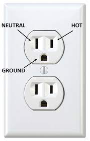
This is how a plug should be wired:
Thanks I will test that and post back the results later this afternoon after work.
1 Like
@donkjr I got the new power supply in today and have mounted it and hooked up all the connections.
I have a couple question though.
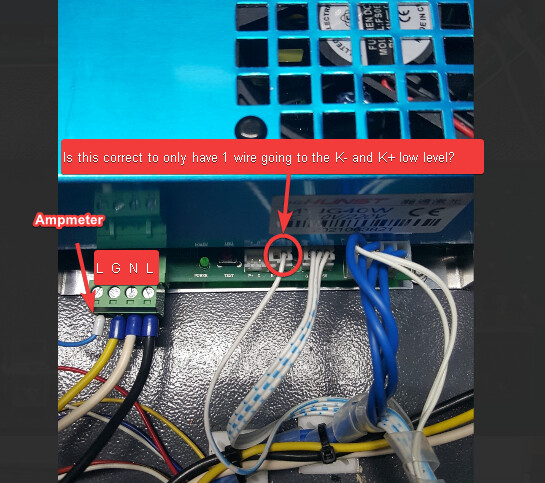
Is it normal to only have 1 wire connected to the K- / K+ Low Level?
Also should there be a jumper over the P+/G in order for the Laser to be able to fire?
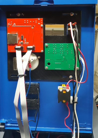
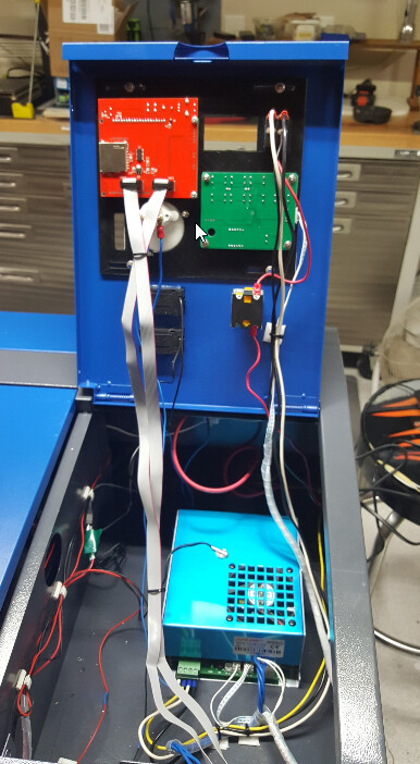
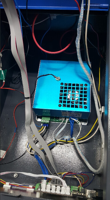
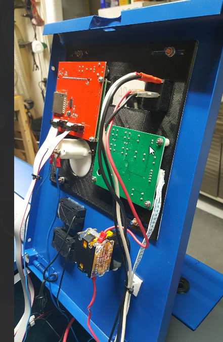
Below is a picture of everything that is hooked up to the new LPS.
Here are the results from the test I did that you sent me the details on.
L-N =110V : I got 123.3V
L-G =110V : I got 123.3V
N-G= 0V: I got 0V
With the multimeter leads connected to the ON/OFF switch and in the ON position I test the Emergency Stop button.
With the power on and pressing the Emergency Stop I was still getting 4.54 Volts reading on the Multimeter.
This is how I am wired and I tested from the two top switch connections and the ground wire.
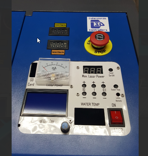
Post picture of your control panel pls.
With the digital control panel, yes.
K- is just another G. K- and G are connected at the power supply and also at the control panel. That’s why they usually don’t bother with hooking up another wire which wouldn’t do anything. There already is one for G.
The person who designed that power supply thought it would be neat to have a two-pin plug for the test fire button. That’s why it is like that.
1 Like