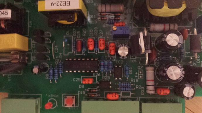
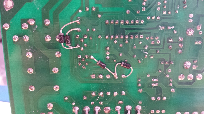
My k40 psu blew up when i pulled and pushed my usb cable into my laptop. Since i studied electronics at uni, i thought i should be able to fix that in a sec. The big schottky recovery diode next to the 12v regulator blew up (shortened) and the full bridge driver which are the 4 transitors in a row on the left(one npn transistor blew). I will draw up the schematic since the design has several flaws. The main one: No separation of the mains! So there is only one rectifier bridge between me and the mains. Opto couplers are implemented as barriers for the controls but all grounds have been connected to the minus of the rectifier, so these become superfluous of this flaw. No ‘snubber’ diodes on the driver bridge so soldered those in as well. My conclusion is that the designer took various power supply designs and cobbled it together without understanding of the electrical principles. Please be smart and add a seperation 1 to 1 transformer to protect your lives! After fixing the hissing is gone when I switch on the high voltage. I guess this was the leaking high voltage through my usb connection. The laptop was dead for 5mins and miraculously recovered, god thanks!
I have been trying to get an old one of these to help understand the interface and the failures everyone is having. Have been searching for schematic and would love to see the schematic you come up with. I would check all the grounding in your machine as the USB part of this failure is strange.
@donkjr thanks. I will try to draw the schematic this week. Once you see it you will understand the ground wire flaw. 
Yikes! I haven’t even unboxed my K40 yet (it’s killing me, but I’m just too busy right now). This makes me want to be extra careful when I finally get to plugging it in. Thanks for the warning!
Yet another reason why these machines MUST BE GRIOUNDED to a GOOD GROUND ROD SYSTEM INDEPENDENT of the mains wiring.
Them Chinese folks aren’t exactly known for their excellent electronics, only that it’s cheaper because of all the shortcuts they take. Separation from mains? Pffft, as if they give a damn. Plug in, it works? Great, ship it. If it blows up tomorrow, not their problem …
I doubt the solution to this problem is provided by a rod in the ground vs using the gnd in your mains.
However, something surely doesn’t make sense.
For the gnd on the usb connector to create this much damage is perplexing because it suggests that something inside this machine is floating and the USB cable provided a ground return which was drawing current. The gnd of the USB should not have been at a different potential than any other gnd in the machine.
The gnd on the usb connector is at logic gnd (the controller gnd) and that controller gnd is tied to the gnd in the LPS and the LPS has two grnds (one from HV return and one safety) which is connected to logig gnd. I checked these in my machine and the are connected and they are all < .4 ohms.
None of this failure sounds normal or good…
I am pretty sure that switch mode off-line power supplies do not use isolation transformers however there is a flyback transformer of some type. The fact that it is an offline design does not in itself make it unsafe. Most of the brick supplies used today are offline switchers with no isolation transformer.
That is not to say that this LPS is a good design. Something is certainly wrong as many people are popping them. Maybe it is when they plug their USB cable in …
Lets wait and see what the schematic shows
Some switcher design info.
http://www.edn.com/design/power-management/4364011/Designing-offline-ac-dc-switching-power-supplies-brick-by-brick
A rod on the ground will definitely NOT solve the problem
But it will protect you BECAUSE of the problem - and others, that are prevalent in the design of the machine
My simpler point (without all the tronics stuff) was that if we have machines that are “grounded” and something is floating inside, the ground is already not working and the machine is unsafe … but it would likely “hurt” when you touched whatever is floating.
I just wanted to make sure that folks didn’t think that grounding in another way would make this problem go away…I think we agree on that.
My advice and what I have done is to do all you can to insure that all the grounds in your machine are at the same potential. Best to actually measure it with a meter.
With an ohm meter:
Check the green/yellow wire that goes to the back of your machine from the LPS AC connector is connected to a bare metal spot on the case.
Check that the gnd on the LPS DC power connector (blk) is connected to the green/wht wire.
Check that the green wire on the LPS AC connector is connected to the green/yellow.
Check that the usb plug is connected to the black wire on the LPS dc connector.
The meter should read <.4 ohms
Just want us to be safe!
Hmmm I’m thinking 4 ohms is a bit high - should be ideally - zero - and resistance indicates a potential problem but yes we do agree grounding the letal box is just for protection - ain’t gonna solve any engineering problems.
I think it says .4 ohms that is close to zero 
I will put in another plug for someone to donate a dead LPS to me so that I can help us know what we are dealing with and even be able to improve and repair these things.
Excellent, hopefully the design won’t change too much between production runs.
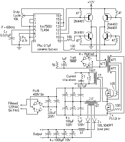
@donkjr repair is quiet simple since the design is very basic. The high voltage part should be isolated. I think that is easy to accomplish by removing the common ground. The high power psu is driven by a tl494 pwm chip which gets its 12v from the low voltage supply. Will publish that schema soon so it will show you the issues. Fairly easy to understand. Just google tl494 psu and you get the basic designs.
This is a very close similar design. Except for the ht transformer which is not rectified and its primary connection goes directly to the laser tube. The current wave form is fed back to the tl494 to regulate the voltage on the tube. This circuit does have the snubber diode on the bridge. Ours doesn’t. … further imagine the minus of the mosfet in the ht circuit is grounded to the rest. Ouch.
I don’t really know what you mean by HV section isolated certainly not the common ground.The last thing you want is any chance that the HV ground gets to a potential above safety gnd. Actually any gnd for that matter.
The return current from the tube must be returned back to the LPS directly and it also must be connected to safety gnd.
In actuality the gnd wire from the laser tube is a single wire that returns to the supply so the tube current is isolated and not flowing through any other path to gnd. That gnd is then connected to safety gnd in the supply.
The return line from the supply is not dangerous in fact it is about 10V across the current meter at 20ma.
Gnd is not dangerous is is not floating from safety gnd.
The schematic is interesting but I would guess not the same as the real one. The output caps on this are rated at 10V, the supply outputs many 10,000’s of volts :). I think our supply’s have a flyback and HV voltage multiplier but I have not seen the real schematic. Looking forward to yours.
@donkjr indeed this schema just show the principle of our k40 psu. None of the values applies of course. Hopefully i have some time this week to draw it up.


