My first Freegrid design: ER11 tray in nine freegrid units

I’ve been vaguely acknowledging the need to get my shop drawers and surfaces in order. Cutting shapes in high-density foam is a classic, but I keep buying new tools that I didn’t previously think about, and cutting out a foam holder for my most accessible drawer — where I need this the most — doesn’t feel good.

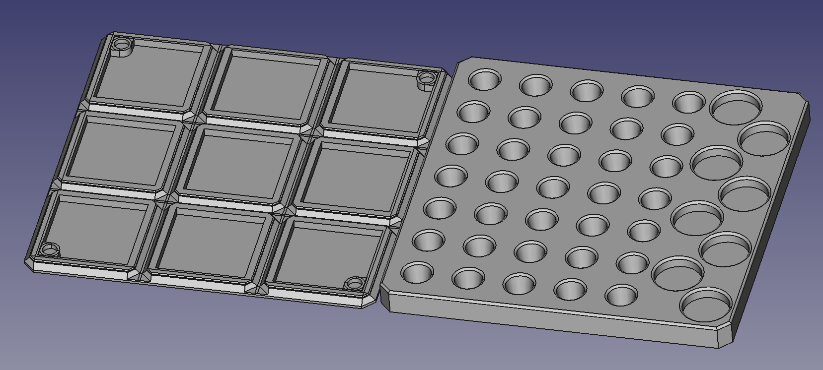
I recently stumbled on the in3d Freegrid system. 50mm by 50mm unit spacing, optional magnet attachment, 3D printed, generated in FreeCAD with macros so that your mind is the limit for adding new modules on top of a general grid. It’s very new so it doesn’t have much in the way of documentation yet but I’ve already helped a little bit with code and am likely to help with docs as well.

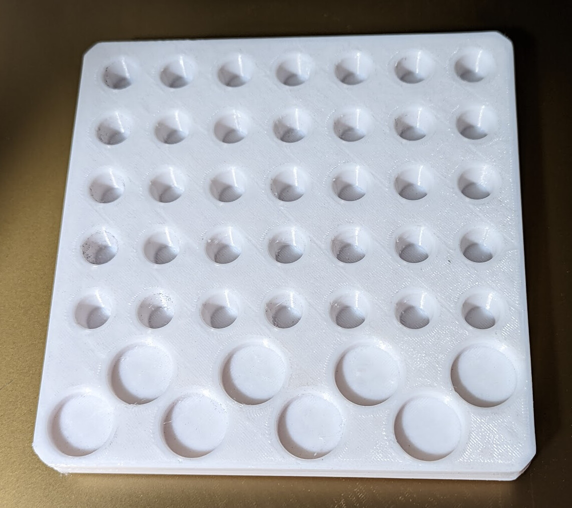
I already had a version of this tray that was 150mm x 160mm, so it wasn’t hard to imagine tweaking it to fit in 150mm x 150mm. I had printed that older tray in PETG, and wrote the collet sizes on the top with sharpie. PETG wicked ink from the sharpie, so I decided to print the new one with PLA to see whether that works better.

I succeeded!

But wow was that a rabbit hole.

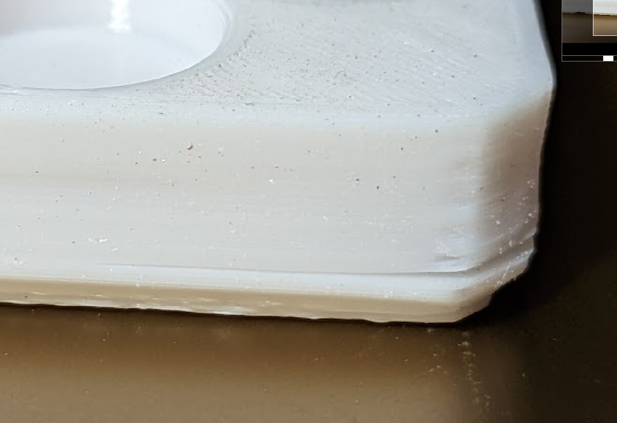
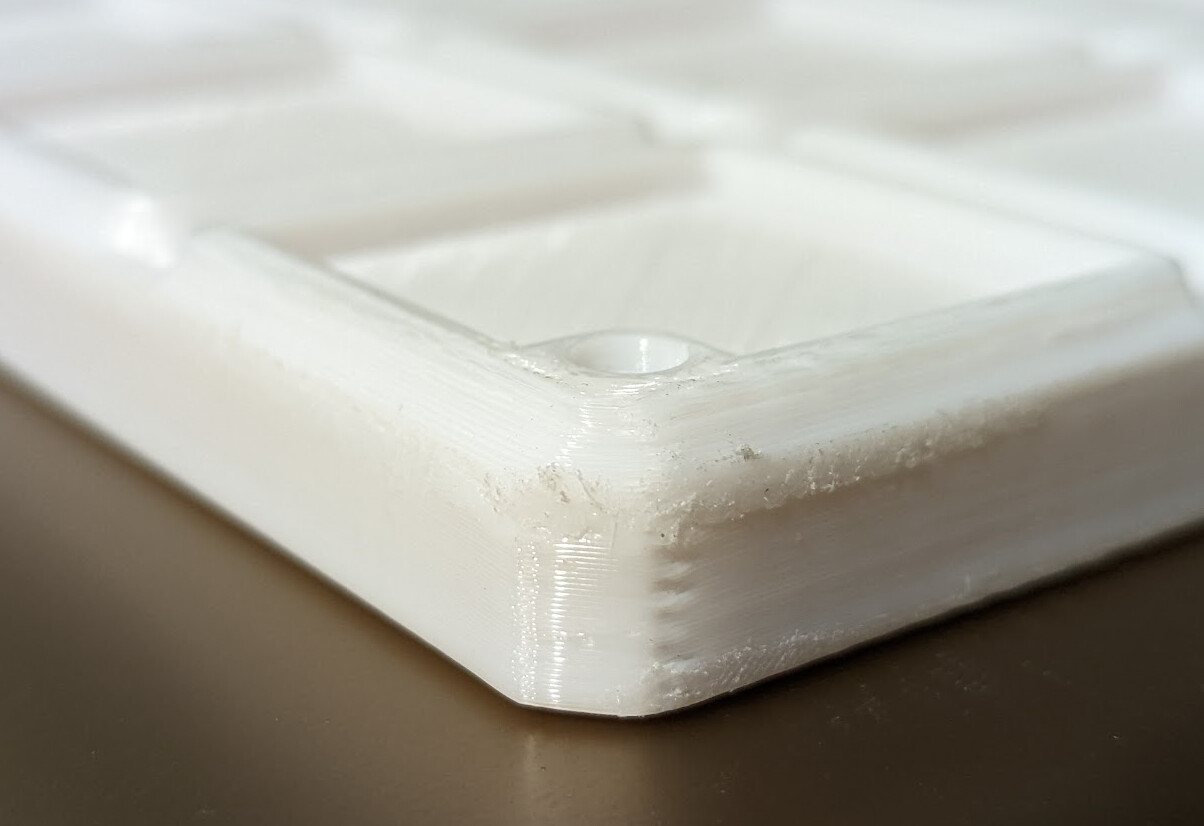
Large flat dense objects without an enclosure and with limited bed adhesion warp easily in PLA. Waking up to this was a disappointment:

After several experiments, I determined that overhangs were curling up (regardless of cooling or speed I printed them at), and that “external perimeters first” avoided most of that curling and led to an almost successful part.

There’s no way that magnets in that lifted corner are going to snap into place in a grid. :sob:

Ultimately, I ended up cutting it in half and printing the cut halves on the bed for maximum adhesion, and got only a little lifting at the corners, but enough flatness to glue together.

Part of the rabbit hole was switching to the pre-release of Prusa-Slicer and using the Arachne perimeter engine, and another was that Arachne makes a 0.6mm nozzle make sense, so I swapped nozzles, which led to replacing the entire hot end up to but not including the heat sink and doing re-wiring.

And I still don’t know whether the PLA will work better as a writing surface after I sand/iron it.

1 Like

Thats the coolest looking fail I have seen so far!

For me it would have been a piece of 1/4 fiberboard and forstner bits. :wink:

1 Like

Leave it to @donkjr to stay level headed!

I’ve generally resorted to putting round removable pads at corners when there’s repeated adhesion problems at corners.

@dougl yeah I’ve heard them called “mouse ears” — after a bunch of prints, I’ve realized that shrinking plastic above is what’s pulling it off. Even the version that I split apart so that it had a complete layer across the whole thing still pulled up a little bit at the corners. I don’t think mouse ears would have helped in this case.

@donkjr I’ve been thinking about combining CNC-routed tops with printed bases and gluing them together. I’m not yet satisfied with my solution for R8 collets. The ER11 collet holes here are tapered to match the collets, which is probably silly but was meant to make it easier to pull them out.

1 Like

That’s odd since I’ve never had PLA shrink like that. ABS is a given for major cooling/shrinking issues and I’ve often had to place a box over the machine to prevent air movement in the room effecting cooling of upper layers. For years I’ve printed PLA on glass using only school glue stick and on my Mini Kossel with no heated bed. But there are so many different vendors and mixes.

Right on the “mouse ears” naming now that you mention it.

I have another printer that has an enclosure, which tends to help with shrinking. But I think that one reason for shrinkage is that I’m printing fast and hot. 150mm/s and 125°C 225°C and I think I could have gone faster. I’m printing hot so that I can go fast, but the hotter and faster the more shrinkage, up to I think 3% with PLA. I could buy a larger piece of glass and use a custom Z offset for printing PLA, but it would be a trick; because I probe and tram with an inductive probe, I’d have to level with the PEI sheet, then swap it for (or augment it with) glass, then wait for the glass to heat up, then print with an offset.

I glued the pieces together with CA glue, and here’s the worst resulting corner from the shrink-induced lift:

I chucked some filament in my dremel (one of the collets almost fits it; well enough to bodge) and found that 5K RPM and starting with up to 12-15mm of extension beyond the tip of the dremel let me friction stir weld.

I did file it down after laying a bead on the theory that these things might eventually need to sit right next to each other in the grid:

The technique that worked best was kind of tig-like I guess — get a puddle started in one spot, then move about 1mm at a time, dwelling a bit over a second, to lay down really tiny “dimes” of plastic on a small line. For the big gap, I had to first fill inside, and then I could run a bead on top of the fill. For small gaps, I could just walk along until the filament was right up near the nose of the dremel.

while that is pretty quick for a non-delta machine that temp is just wrong… PLA typically is melting at 175-180C and I usually print at 210-225C

Typo: — 225°

Higher than normal high end of 220° because it’s measuring the block not the filament and it’s running through pretty quick at that rate. :relaxed:

1 Like

the splitting also looks like layer adhesion issues and also probably because of printing too fast.

My guess is that you are setting your machine speed too high and pulling the plastic which causes the tension. Maybe you got your extrusion width set by adjusted extruder multiplier or adjusted slicer for narrowed/stretched extrude width setting. Either way, pulling the plastic too much effects results and as you’ve experienced costs lots of time in the end.

I often have 3 settings/configurations for my plastic rolls(color effects absorption) which are basically speed and quality based. I’ve also found that I can get lots of time saved with a high travel speed setting and limiting or eliminating Z moves(especially on Cartesian machines). It just doesn’t pay to go beyond speed at which acceptable quality results. For those I just increase layer thickness but generally I print at .2mm /layer for everything and then employ variable layer heights when special details are needed or overhangs look problematic.

That’s not layer splitting.

I printed two halves and glued them together back to back with CA glue.

It’s just that the corners on the thicker part lifted, and when I glued them together they weren’t quite flat.

ah, I’d thought you split it horizontally, not vertically and were showing repairs. Yes, I’m that anal about the fact that I didn’t see the split in equal halves so it never dawned on me that was a purposeful split of the model.

I don’t know what you mean. I was showing how I filled in the crack where they were glued together.

This is what I printed:

The corners of the thicker part pulled up slightly (around 1mm). I glued together the faces that had been on the printer bed. Where the bottom wasn’t flat, there was open space at the corners that I filled by friction welding.

? regarding which comment? I had understood when you said it wasn’t layer issue but was where you split the model. You said you’d split the model IN HALF and those were not halves so I figured it was a repair of one area where you had more bed adhesion issues. I get it that you split the model horizontally.

I did split it horizontally, as shown, in the model.

Splitting it arbitrarily in the middle of the collet holes wouldn’t be valuable; it could only reduce the surface for gluing and result in potential imperfect alignment inside the holes. When I split, I look for splits that will have minimum impact on the part; that’s my idea of being anal about splitting. :smiley:

And my real goal here is that I have a general base unit onto which I can glue arbitrary different top units with different features, like one for my R8 collets for my mill.

I have a lot of these to design and make.

I bought 1200 magnets to get started.

I think both printers are going to be busy for a while.

1 Like

ya, sorry I had visualized splitting the physical model in a left and right half and my fingers just went with that. Definitely the wrong description since we generally talk about the direction of the “knife”.
Making a model smaller is how I think of solving warping issues because I’ve always experience warping over large parts vs small parts. It never dawned on my to keep the footprint and split it vertically.

Now that makes sense but solving the printing issues means that part would stay in the design phase and not in the printing phase.

Not necessarily.

At least, not for me.

They are already initially separate in the design phase. At first I didn’t see the benefit of preserving that through the manufacturing phase. In fact, once I did, I had to learn more FreeCAD to modify my design to enable it. (I had to learn how to rebase a Part Design Body from being on top of a face of a Part to being on top of a subshape binder of that face. I had to chase the topological changes all the through the model, one node at a time.)

Benefits?

It avoids the need for printing supports, reducing total filament use.

It enables having some ready-made bases printed in various sizes onto which to attach custom prints with less waiting.

It enables easily doing multi-mode versions that have one side printed and the other side CNC routed, laser cut, or even sculpted by hand such as with foam.

It enables printing single-unit bases, snapping four of them into a grid, and gluing an arbitrary-size feature on top. The feature on top might be some existing thing. For example, I might take the hinges off the box for my V-blocks and glue the bottom of it to one of these bases, instead of spending more plastic I don’t need to print out a custom box.

:tada:

1 Like

Big plans, makes sense.