My dark 20 years history in making

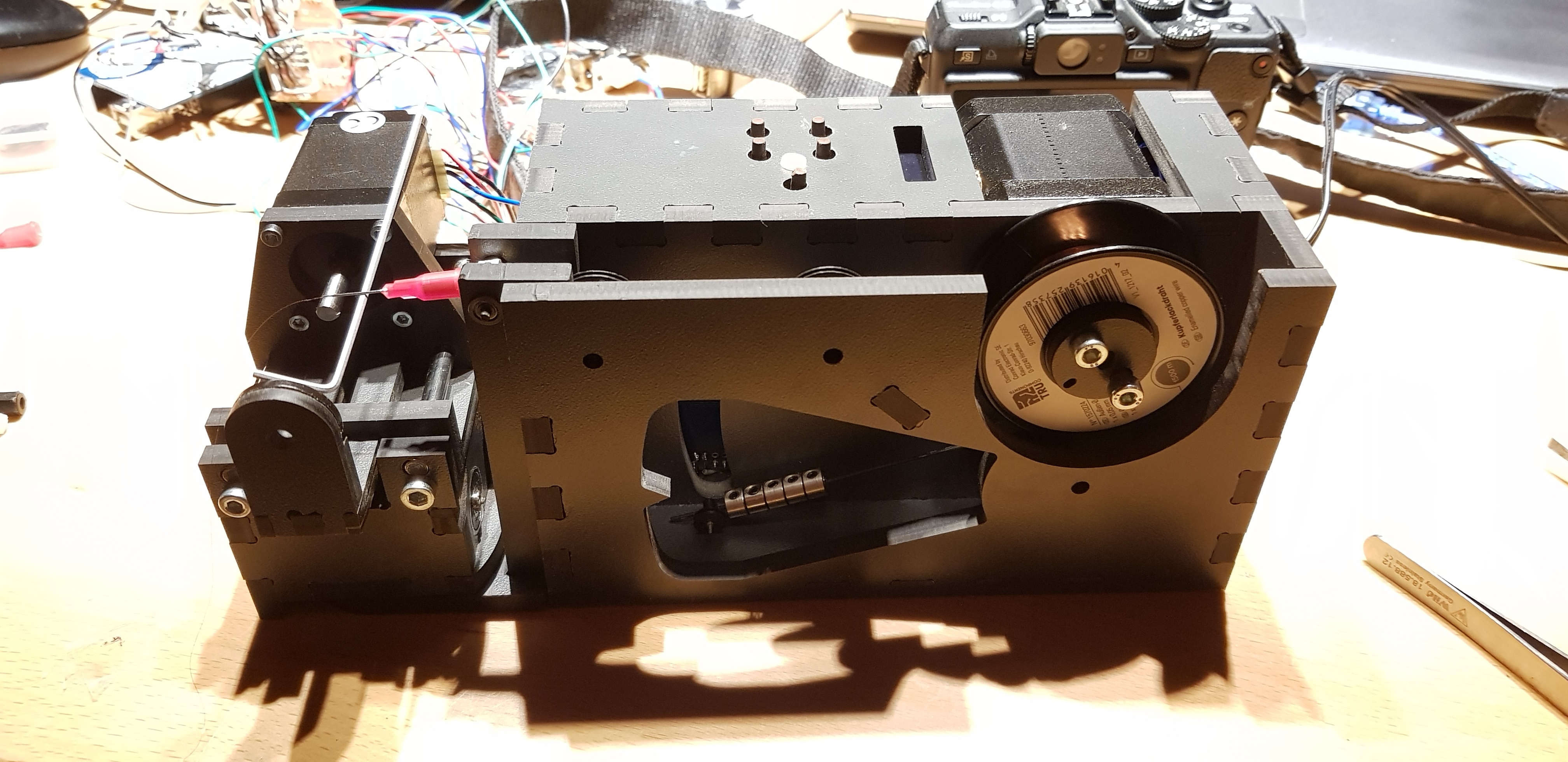
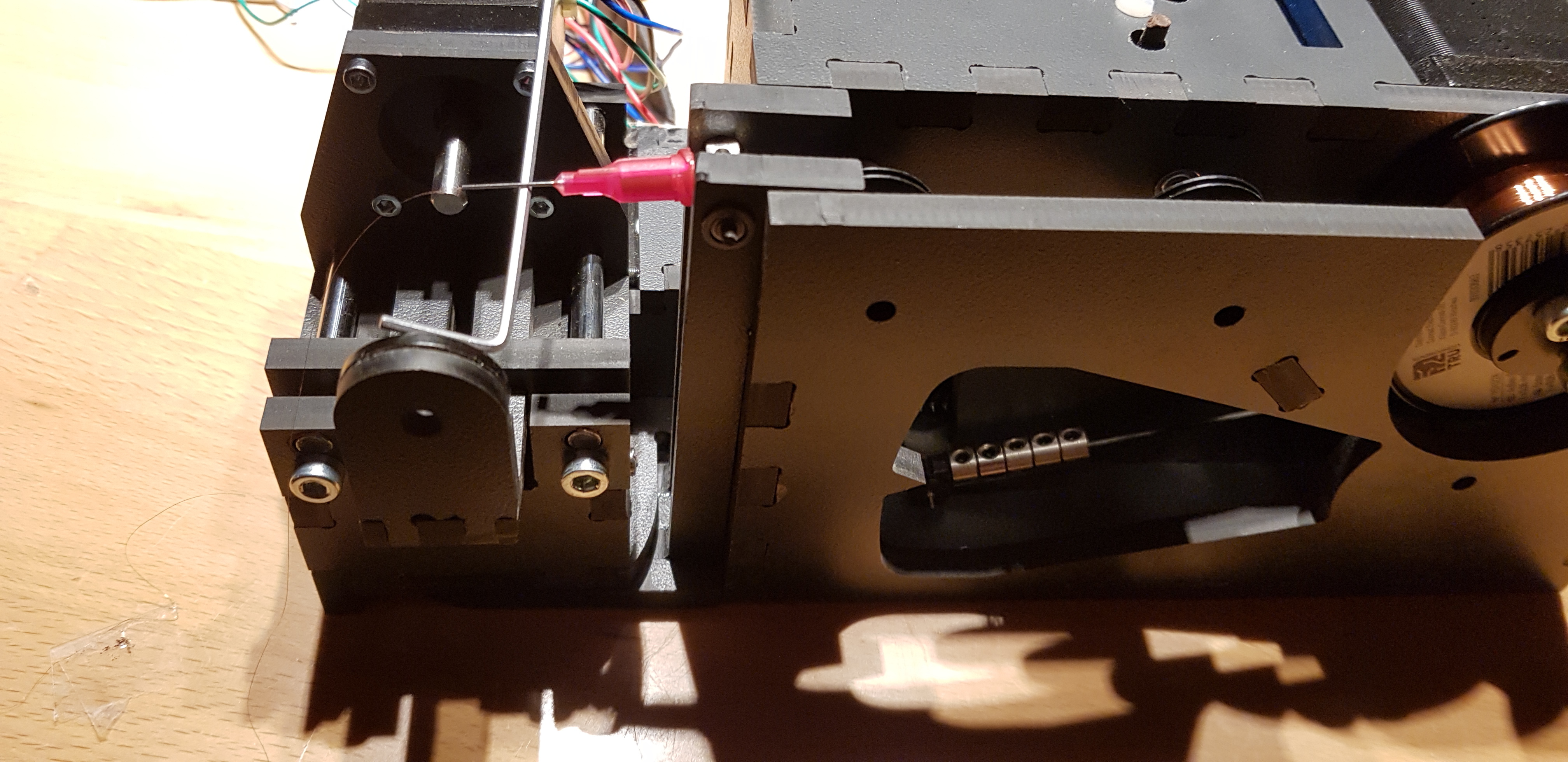
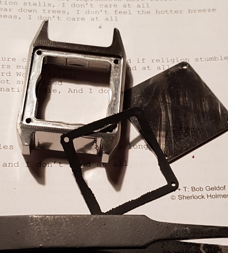
Meanwhile I setup the harnesses of the light barriers… as I try to have a 5 states wire support indicator using an array of light barriers, I recognized that there is too much light emitted so the phototransistors are not fully high impedance. Perhaps I need a comparator PCB to have clear digital signals.
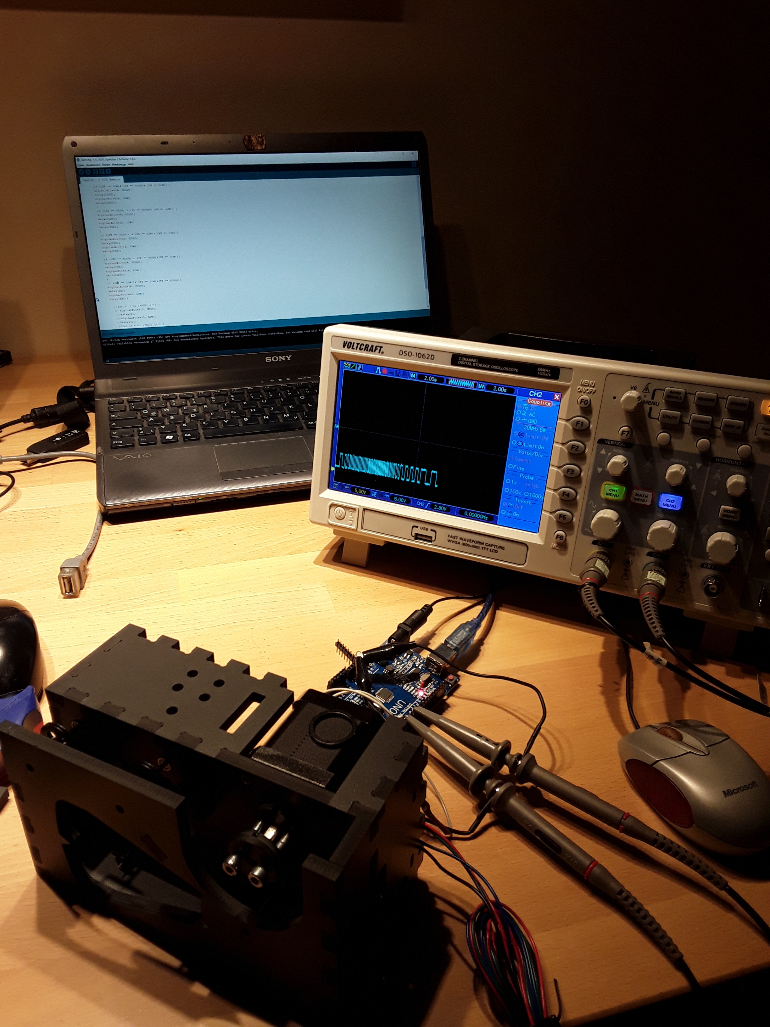
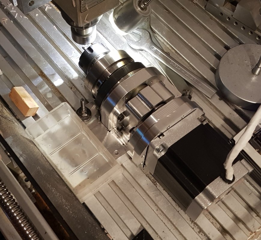
I also did a simple sketch to get the axis moving but recognized a strange thing I will have to check tomorrow.
Each I/O I need is initialized to be an output and pre loaded with the initial state. The sketch consists of two for loops to apply the stepping signals to the polulu driver shields. When the program starts the feeding motor does several steps into the wrong direction before changing to the right one… tomorrow I will have to see if ths would be hardware bound.

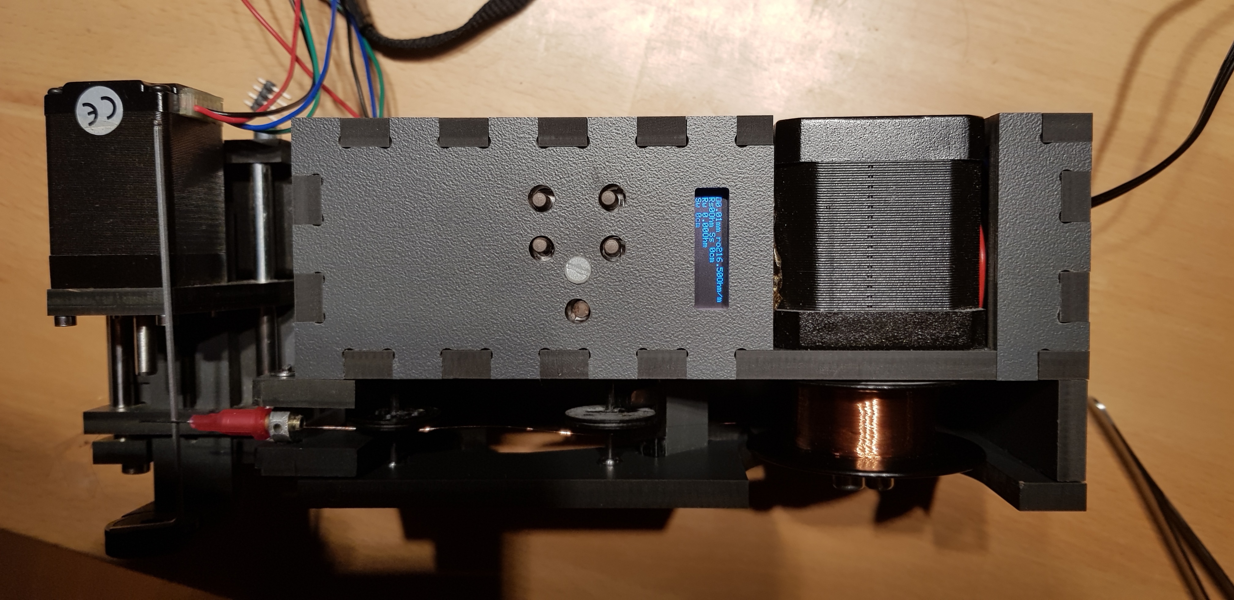
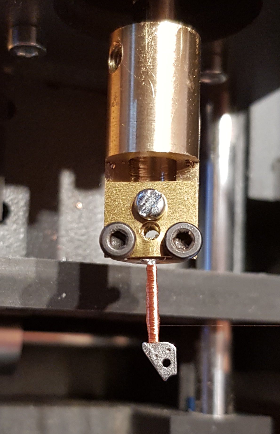
But the stepping feed is pretty acurate for the cheapish setup I run. Step width is between 0.03 and 0.05mm
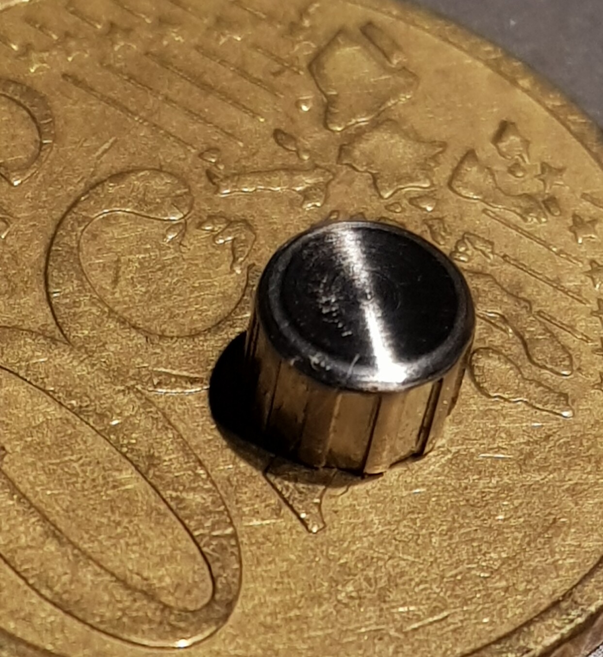
With quite some elastic play under applied load conditions. But how much load can I get from a 0.02mm Copper wire, othogonal to the moving direction. :grin:

But thats it just for today…

1 Like

Today is just short, created some code lines for a discrete cheap control and tested… next would be to connect the stepper stage to the arduino instead of changing port levels only.

The screnn of the oscilloscope shows the 5 weightened frequencies which will afterwards feed the stepper to provide wire

1 Like

Both boards have a very reduced core loop program not to get the controller too much from telling the steppers.
So display and variable parametrization are just open to be implemented, but will probably be added before the winding process and not during… but until now it seems to work… Test is done with 0.05mm enamel wire but 0.02mm should also work

2 Likes

Finished the first revision of the dispenser software
With slightly decreasing the smooth characteristics of the stepper. Now with the right buttons pair you select the wire diameter which is shown with the resistance per meter.
Second is to adjust the resistance you want to dispense /apply then press enter and the dispenser counts the length, calculates the resistance and as the adjusted value is reached it shows an alarm.

2 Likes

First system test on a MIYOTA stator.

Enamel wire 0.05mm Copper diameter.

7Ohm means 7.x m wire…

Wound in rather 35min.

2 Likes

Finally implemented the teach in function for the winder… now its just the case for the controller

2 Likes

Further testing… had a discussion with a colleague and he gave me a few meters of 0.02mm diameter enamel wire from a mobile repair for testing…

Putting this into the device was pure horror but finally I made it and surprisingly the machine had no problem processing this. I ’ m also searching for 0.01mm enamel wire as AWG 54 magnet wire for benchmarking… but a single KG of 0.01 is sold for roundabout 10000 bucks +VAT in Germany… rather 250 KM of wire… but I just need some hundred meters.

2 Likes

While waiting for reply of a possible Chinese wire source,a I thought about what to do next and ended up with the idea of building a lapping machine to grind and polish watchparts.
The concept bases on a half open planetary gear where the object carrier is moving on a hypocycloide trajectory over my mirrorplates carrying different lapping films,!
20200202_183515|243x500


.

3 Likes

Whats left is a nice box around the electronics and some Brass weight and object holder.

1 Like

Turned the two carrier weight elements and thought to initially process those… its very slow . But the results are rather flat… but still with fine scratches … now I will have to find a compound to polish them afterwards…

1 Like

Trying to grok how that works. Any chance of a video showing the underside of that in operation too? :slight_smile:

Watch the previous clip…assume that the weights have centric holes where the pins are picked in and which move the weights (later with the objects stuck to the underside of the weights over the abrassive structure. Pressed down by their own weight ( which may be a little low for a pressure polish…)

1 Like

Hello guys. After a longer break from making , due to “C” circumstances and job change .
I - in February- , stumbled into a new watch project, which I just wanted to add to my list.

.
With exception of strap and movement its all DIY.

3 Likes

Always amazed at your skills!

2 Likes

Love the hex motif!

Is the case cast? Machined? Polished or plated?

1 Like

Sry for posting that little information!
Here is the full package!

Proposal. Designed on Rhinoceros5 and rendered in Keyshot

Case: 1.4112 Nickle free surgery steel, case is routed from stockmaterial, hand ground to remove path markings and polished with corund lapping films, felt and fabric to finish.
Pinholes for strap pins as crown tube hole are milled and reamed to deburr and fit.


Crown: 1.4301 xsteel turned from 6mm wire, structured, threaded(M0.9)milled on divider (also DIY)


Crown tube: 1.4301 xsteel, turned on lathe two cut in seats for gaskets, reamed stepp fpr crown thread flange

Lid / bottom: 1.4301 sheet metal shaped, drilled and engraved.
Gasket, routed from TPE

Movement holder as batterie insulation: POM
Hands: routed from springhard brass , polished reamed and colored
Crystal: hardened raw watch glass disk ground into shape and fit.
Dial: first attempt aerograde aluminium and brass routed , -2 parts - 0.2mm thick backplate +
Structured (2x0.1mm layered front grid was too sensitive to handle.)

Second attempt: 0.4mm thick cut and coloref from stock.


Rehaut : EN AW 8350 machining Aluminium routed and structured from stock. Varnished.
Movement mid class ETA Quartz movement
Strap: modified HIRSCH leather strap with Buckle.

2 Likes

In parallel building some furniture from ply wood/ bamboo… and Aluminium - big vs. small


3 Likes

Amazing work! Thanks so much for sharing. :smiley:

Finished my Watch…

Seems to be a good daily rocker…

5 Likes

Truly beautiful piece of art.

2 Likes