For I touched many fields of engagement in more than 20 years of making I find it rather difficult to start one thread for each. So I think I setup just one thread to from time to time introduce a new topic. Hope you can live with this solution.
2 Likes
It started all in 1998 when I finished my studies in mechatronics / precision engineering.
I thought to go auto with my slide projectors.
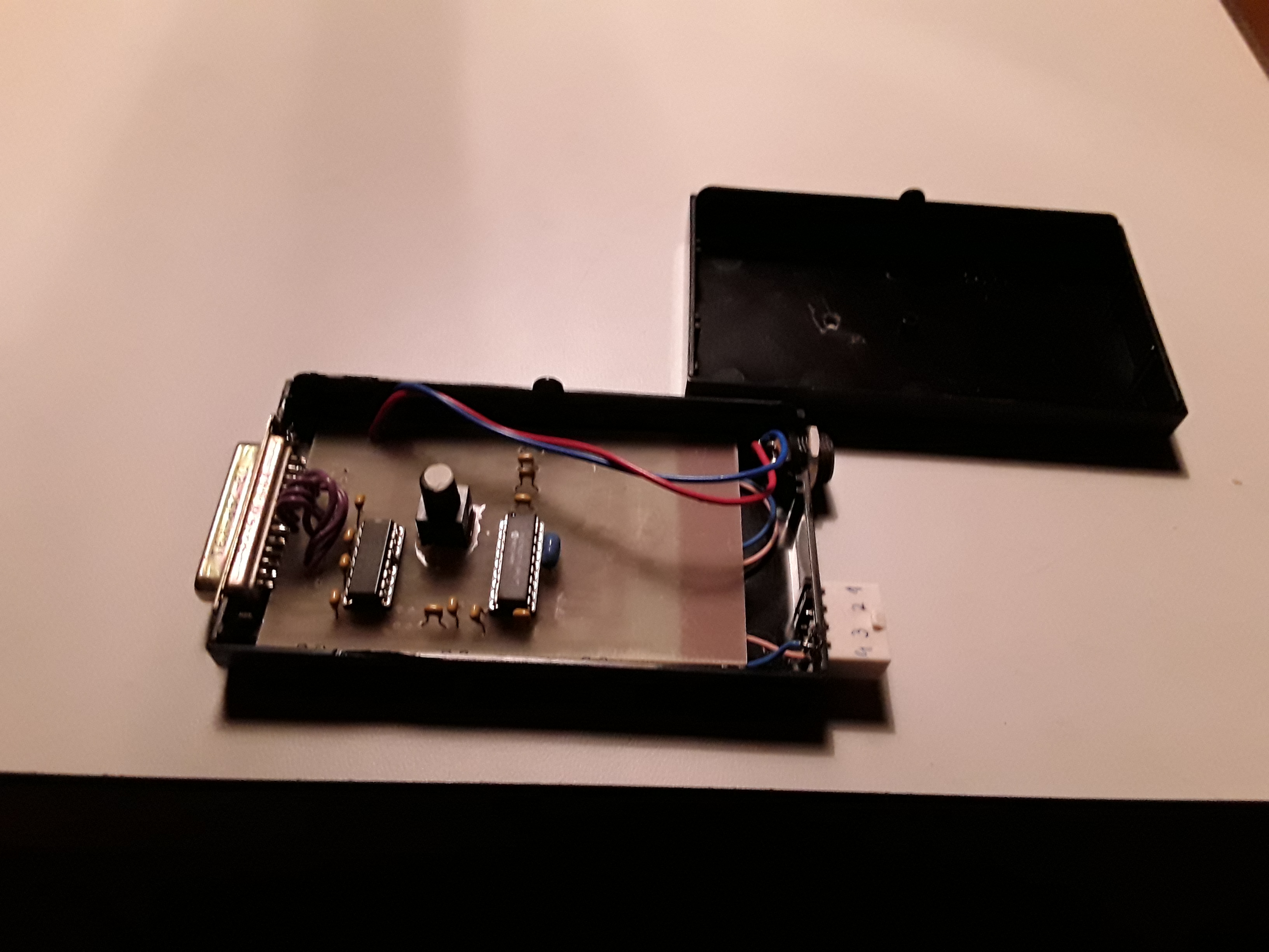
So I built a small controller board which triggered the remote controls of the projectors via opto bank using a PIC controller.
The comunication was solved via RS232 and the command protocol (on a 5 1/4 Disk) was generated via an ASCII table which contained the CD time code of the audio track and was triggered by the running Disk so dependent to the time related signal the two projectors were able to feed foreward and backward
As to fade and blend.
Unfortunately RS232 is past, Delphi( the PC + script/ protocol generator) too and … what is a 5 1/4 " disk, please! One of the projectors was defective and the other had been sold… so the controlbox is the only thing remaining just for sentimental reasons
1 Like
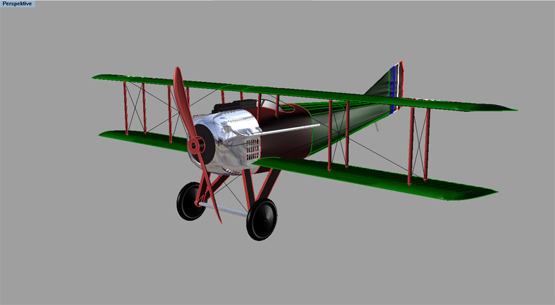
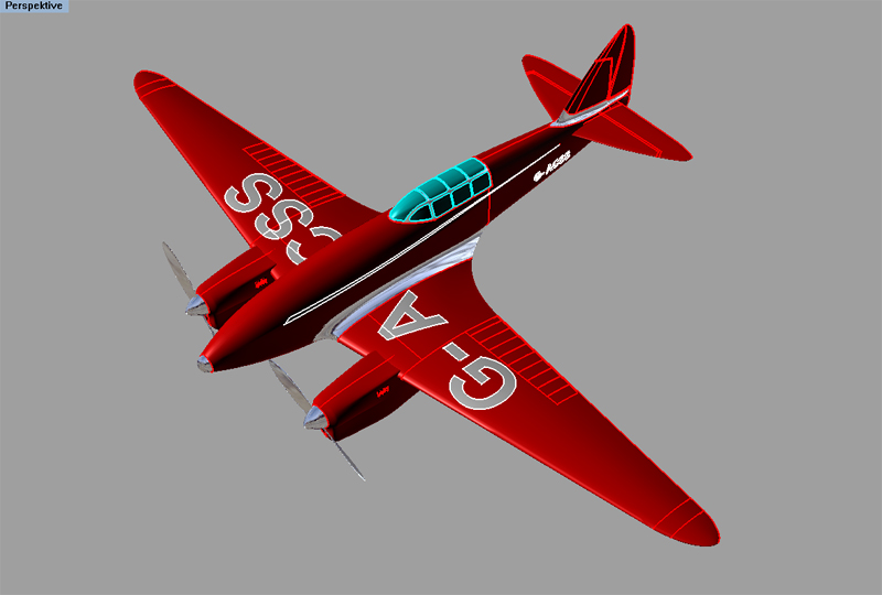
Short after that with the first styrofoam plane wave landing on European costs, two colleagues infected me with the RC Virus. But I did noth want to buy but to build so I started my own work with jigsaw and epoxy. But due to rather bad piloting skills I had to go effective in repairing building and designing new planes.
So I developed a methode to coldform closed cell styrene foam (e.g. blue board / depron etc. Afterwards heattreat and so generate 3d shaped ultra light fuselages and wings…
I m sorry not to poste each of the 146 planes I built over 14years but perhaps 2 or three

The Stuka was the smallest model I ever built. The Rx is a keyless entry chip (so8) which was supported with the peripherals on the chip case, actuators were 3mm coil actuators with 0.5mm carbon rods manipulating the rudders and the motor was a 4x7mm type from vibrating in a cellphone… battery 100mAh single cell placed in the 500kg Bomb under the fuselage. 15.5cm wingspan 3.05grams all up weight… unfortunately too fast for indoors and too sensitive for outdoors, so it did not have a long life

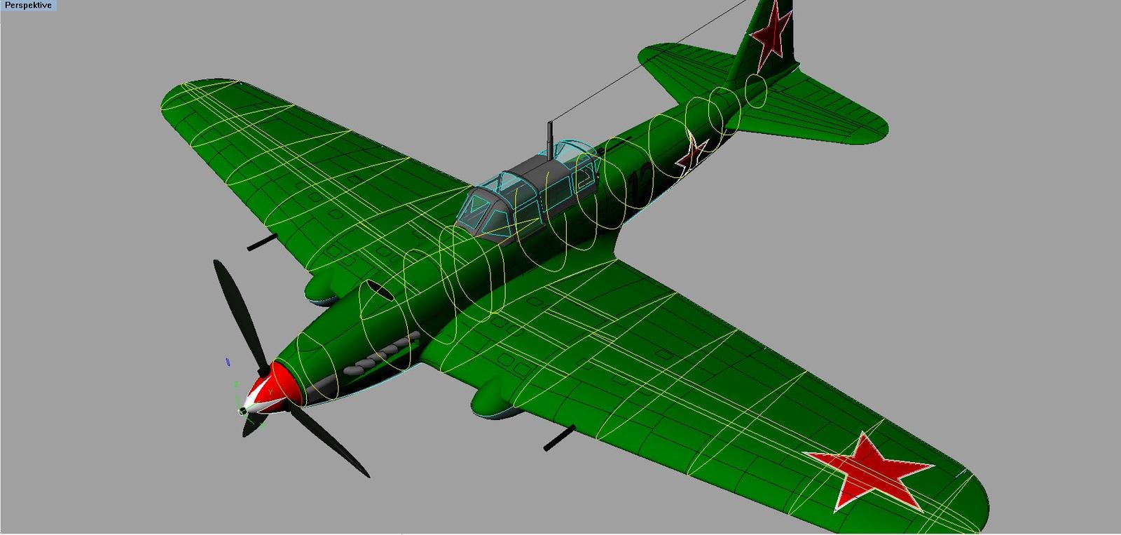
For the 262 I built moulds from modelling board and pressformed the parts includung panellines and structural things about 36 gram AUW 32cm wingspan… a very furious flyer.

For the MIG 3 we organized a world wide modelling workshop on RCGroups.
80cm WS 350 gram all up weight. Built after my method mentioned at the beginning…
The migs previous project …https://youtu.be/_4AeY_xJtac
The big version… https://youtu.be/7WTJTGkiLjs
3 Likes
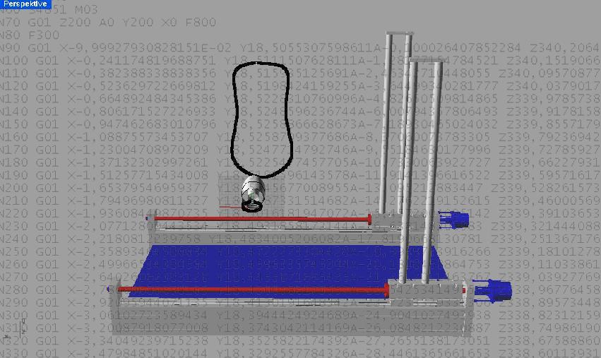
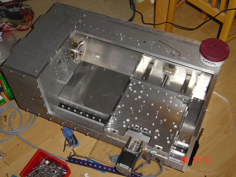
With the rather 60th plane after the same technuque I decided to go a step further and to search for a CNC router to buy. After 1.5 years of research I was not willing to spend that amount of money for the available low precision, and decided to build my own one. But after it went little over budget , I decided that it would have to have additional features for the price.
So I made the concept modular and wrote a preprocessor to generate gcode for wire cutting ability.
5 Likes
A hot wire Cnc is something I’ve never considered before. Thanks for sharing.
There are different concepts out there, depends on what you want to do with the device or what you want to spend… would be probably best to check the cad cam channel of RCgroups at this point as they are busy with that stuff for years now… ( Iwas one of the first posting about and this might be more then 10…12 years ago…)
To proceed with the timeline, I produced several 10 models, kits, planes from EPP for buddies and the club before I recognized it to be boring to do all the same process again… For my previous job I had the Idea for a
Device which I call the CNC killer gun. A portable CNC with which I was able to do quick and precise developmental moves at the customers site, and with the customer in a very quick manner. Unfortunately I had a boss which felt in a way unfortunately affected by the idea and so blocked it whereever possible.
So my direct superior liked it, the CEO too, - but the technical director blocked the idea wherever he was able to.
I’m not permitted to show much of that time as the IP is linked to the company I was working for, but some clips linked to the CNC…
40kg including pc and case, and transportable in a wooden box
2 Likes
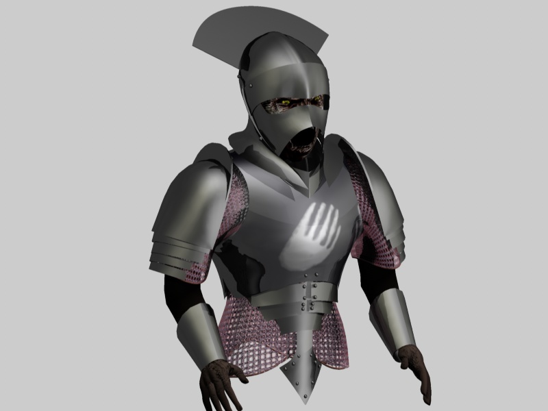
Someway paralyzed by the so called blocking I changed my doing and further worked on my CAD , and rendering skills I own a pretty old licens of C4d and so tried myself in character moddeling… ( this should be an Uruk Hai Orc from the Lord of The Ring, (clan of the white hand)


1 Like
Going through all the planes and builts I did over the years should be rather boring for most non RC - addicted persons so I would continue with eqipping the toolshop.
I passed my studies in Black Forrest, in an location which previously was used as a watchmakjng school. And once a year there is a big watch related meet and greet and trade weekend. Went there , wanted to buy a watch making lathe but that one I wanted was off right before my eyes.
So I got frustrated, went home again and built my own lathe…
1 Like
From that time I recognized that all my walls were full of planes and there was no space left for more… time to change my direction of making. And as the lathe was just finished it needed some testing…
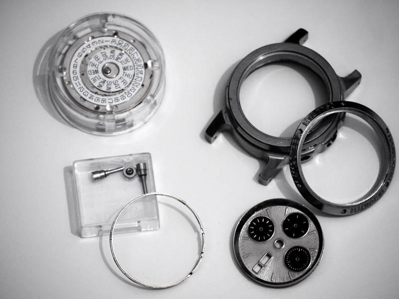
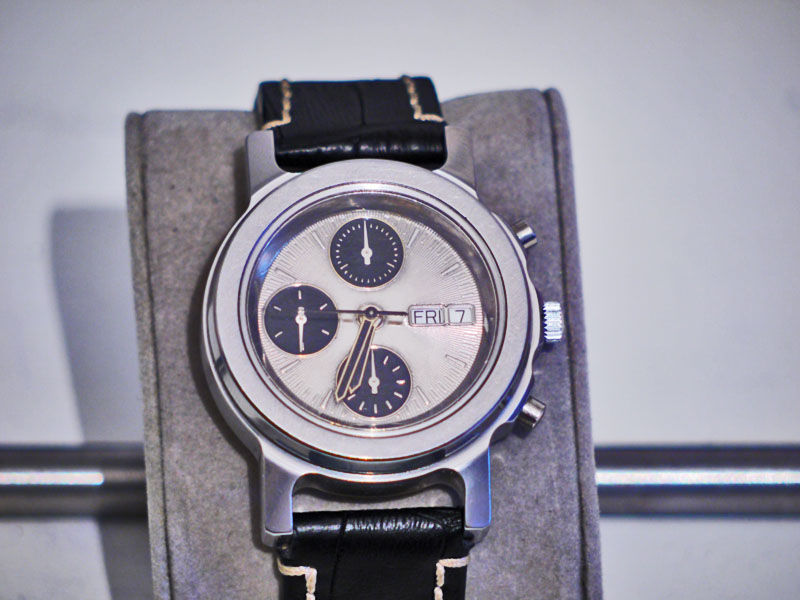
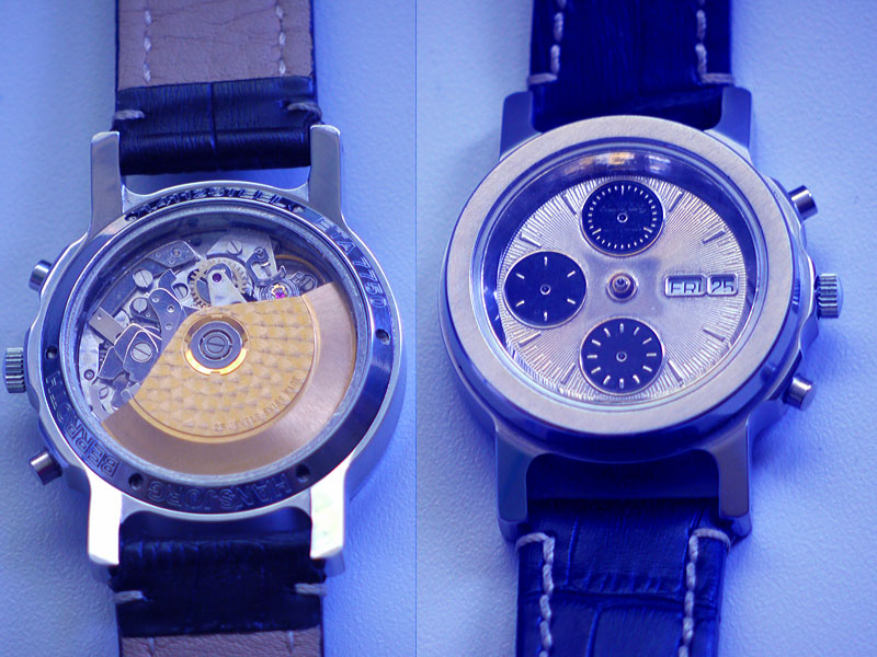
So I decided to buy a Swiss watch movement and started to make the environmental parts from Nickel free Stainless Steel and Brass and gathered my first experiences in electroplating.
2 Likes
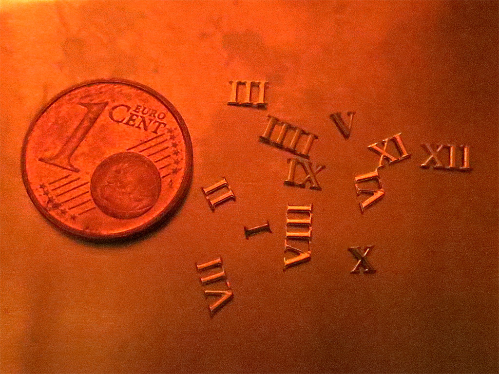
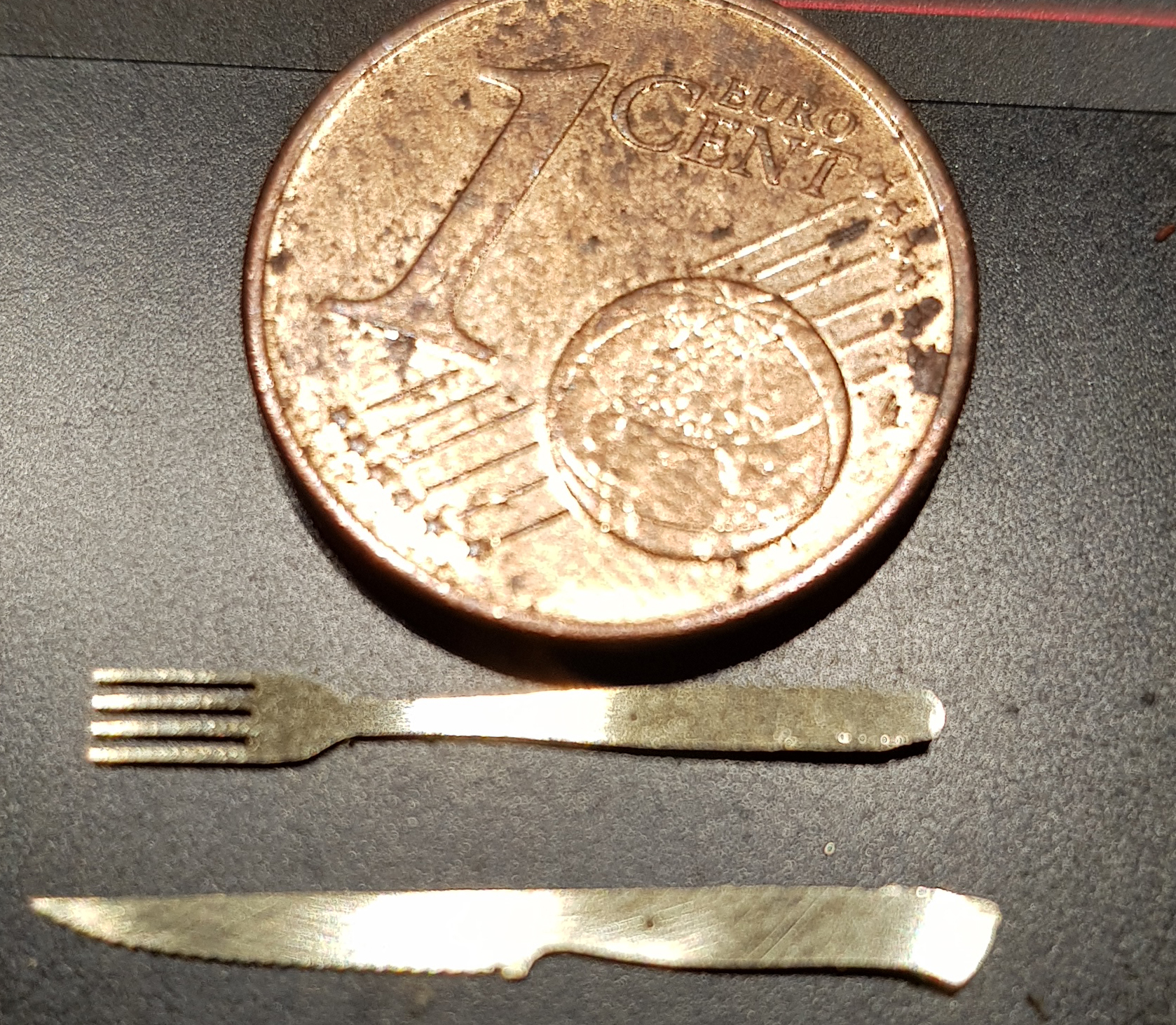
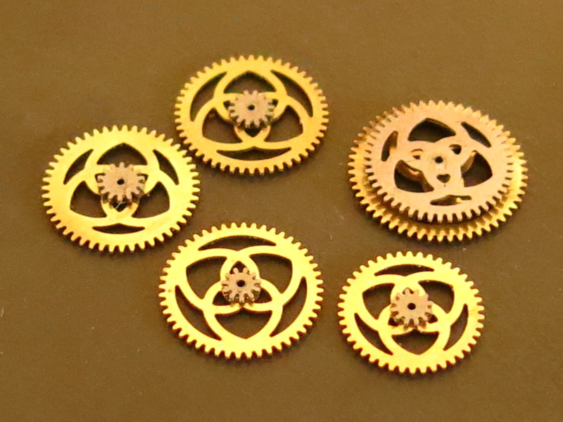
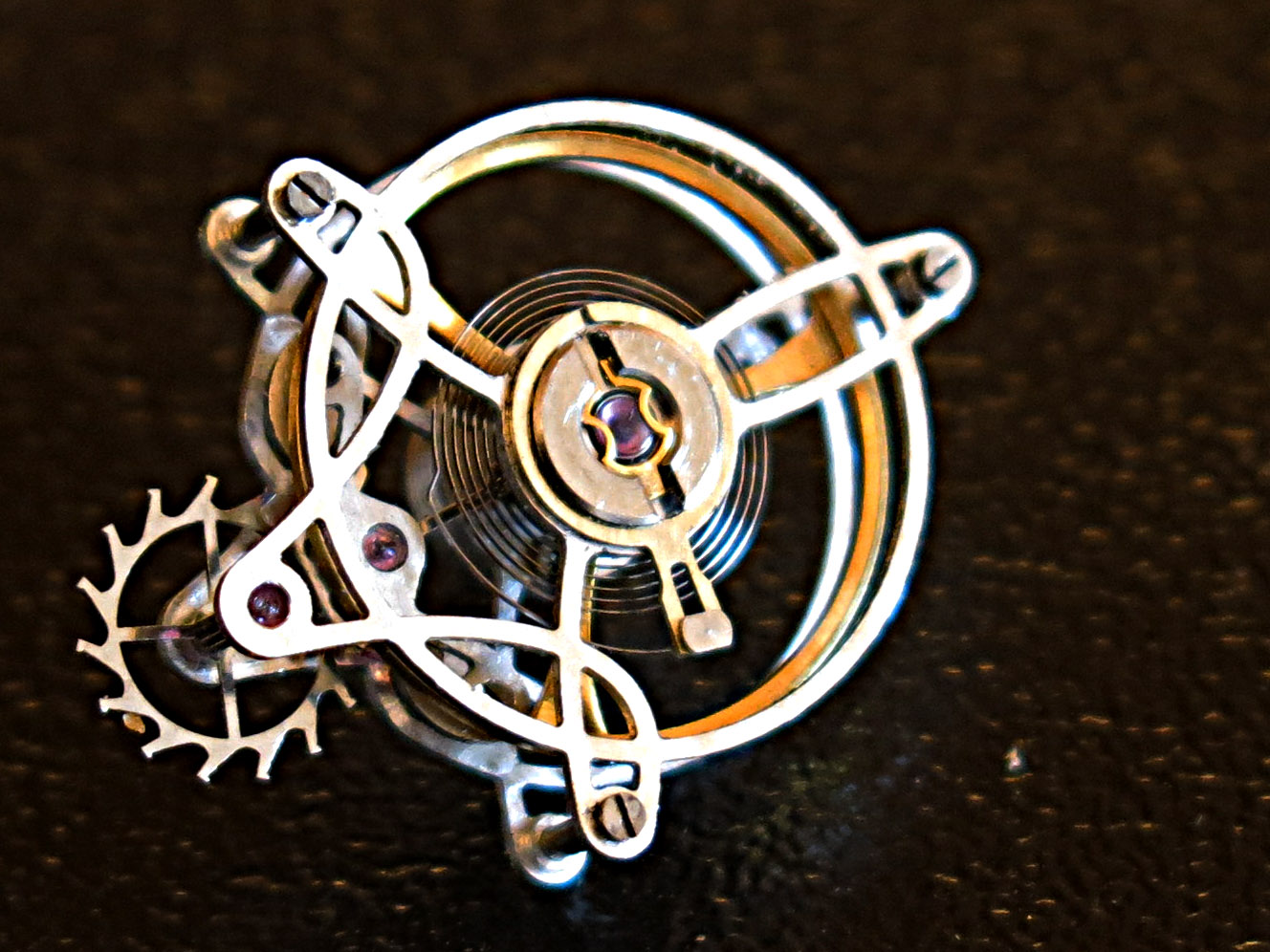
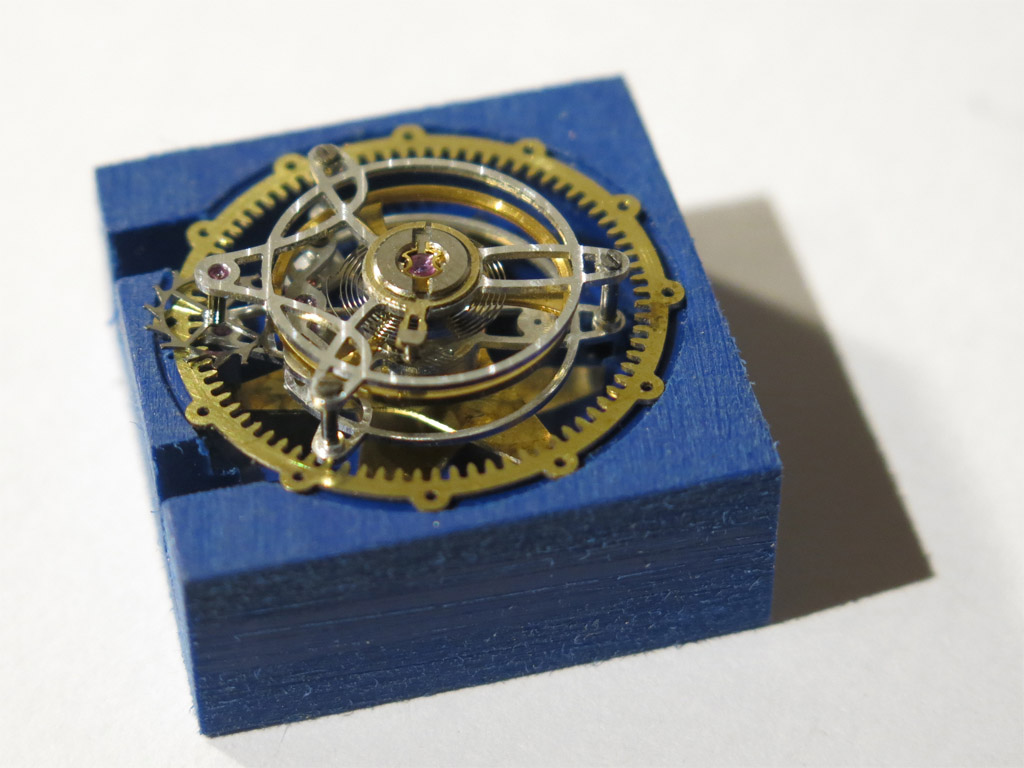
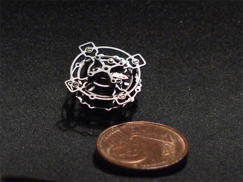
Success raises ambitions, so I thought about the possibility to get smaller in parts and technologies and tried myself in producing watchparts for my own purposes…

3 Likes

I know next to nothing about watchmaking. Did you cut all those parts by using the lathe as a milling machine by putting a mill in the spindle and mounting the stock on the cross slide? (Thanks for continuing to share this journey with us!)
1 Like
Nope. First I bulit a router , then I built the small portable router with the big one (clip above). If you watch the hot wire CAD picture and virtually remove both the posts for the z Axis but add a gantry instead you have my big router. Then I used the big one to build the lathe.
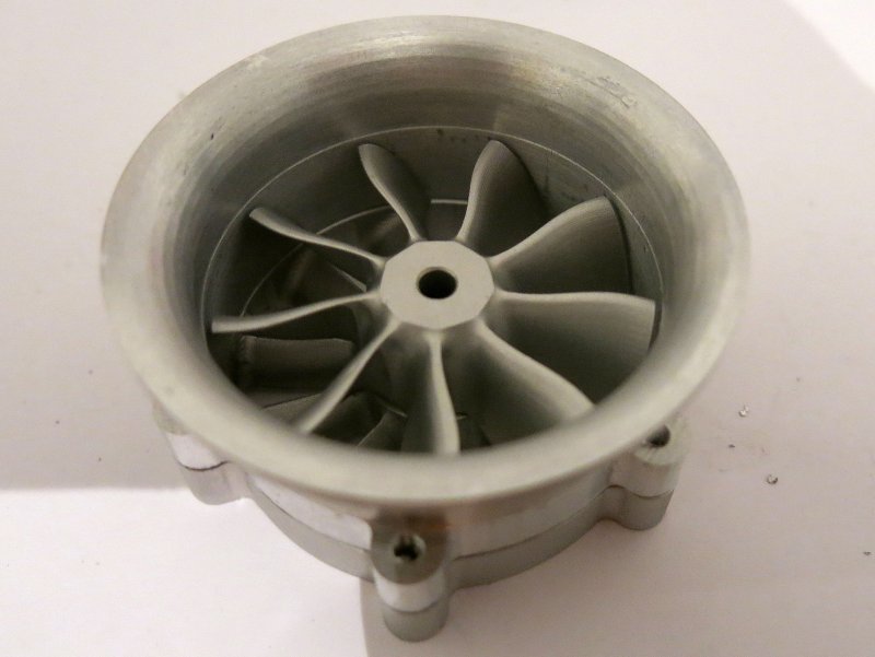
Most above parts are done with the first big router, a few with the lathe.
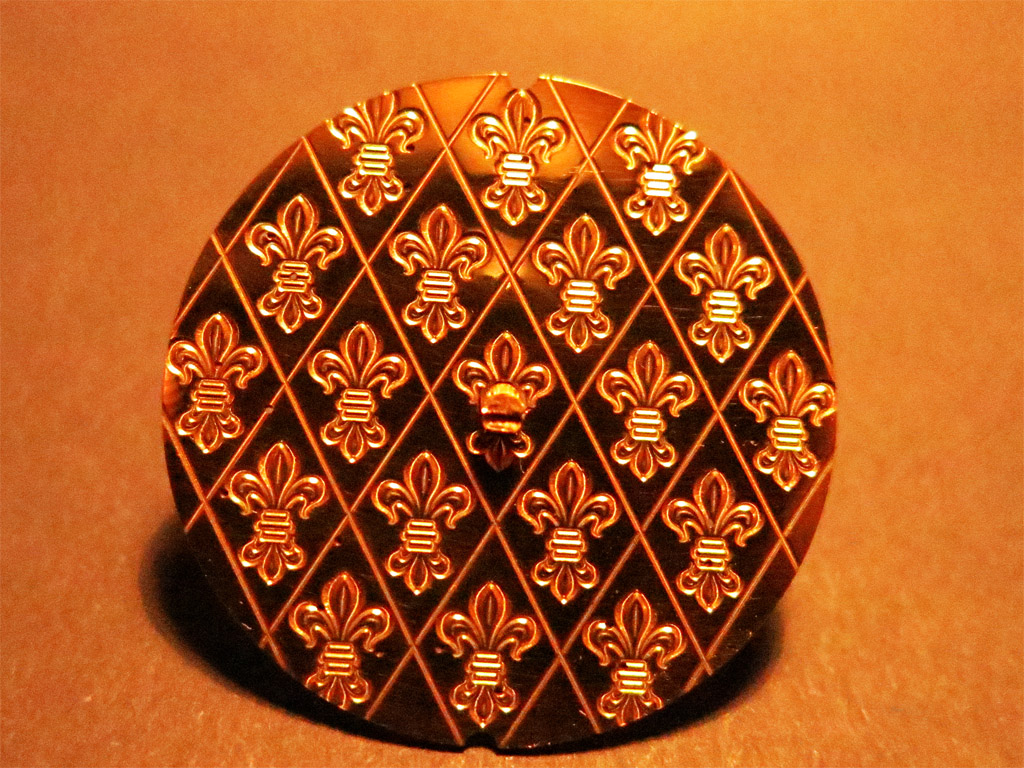
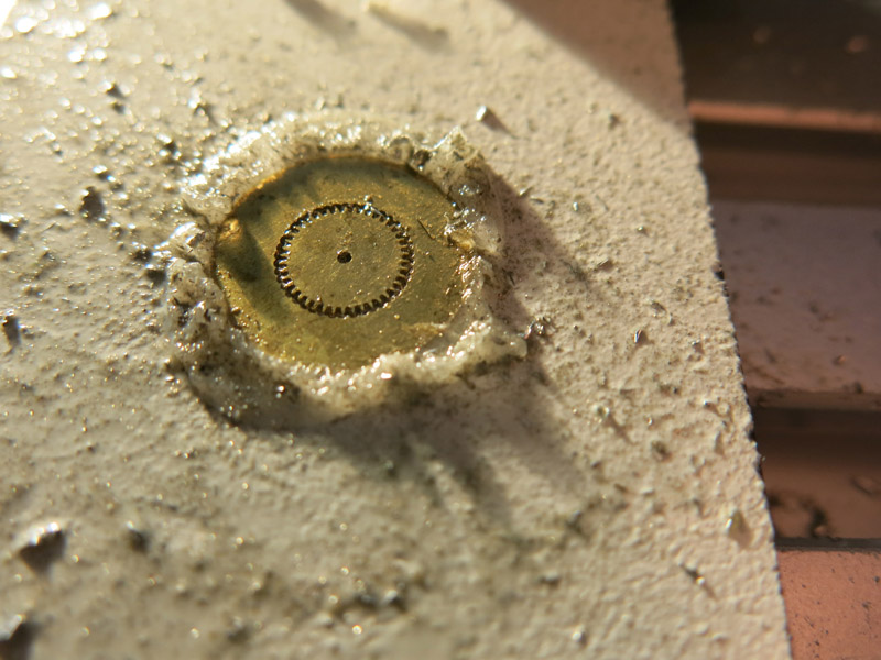
Mostly used tool for that parts is a 0.3mm flat tip shaft bit. Some engravers and bigger flat tips for the surface patterns the posts of that tourbillon in the last pic are syringe needle pieces threaded with 0.5mm from both sides. E.g. the gears are made using a 0.3mm shaftmill . The precision plained brass is fixed to a HPL lost stock plate using CA. The part is shaped and afterwards the CA is dissolved over night in Acetone…
6 Likes
WOW! That is truly amazing!
1 Like
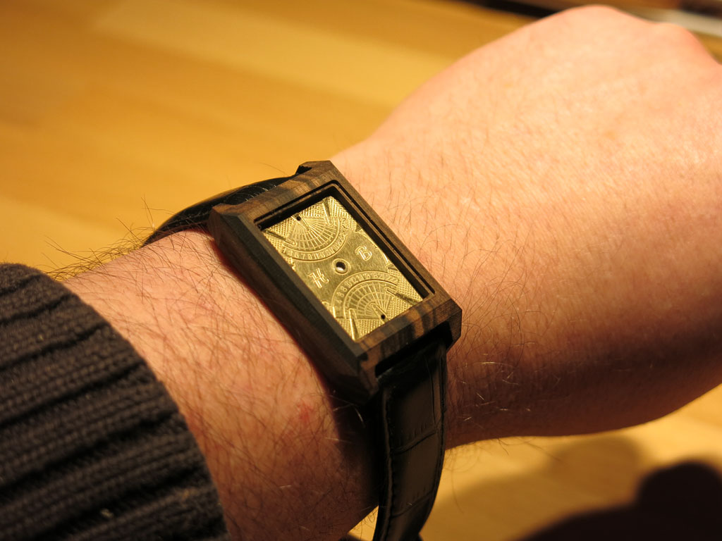
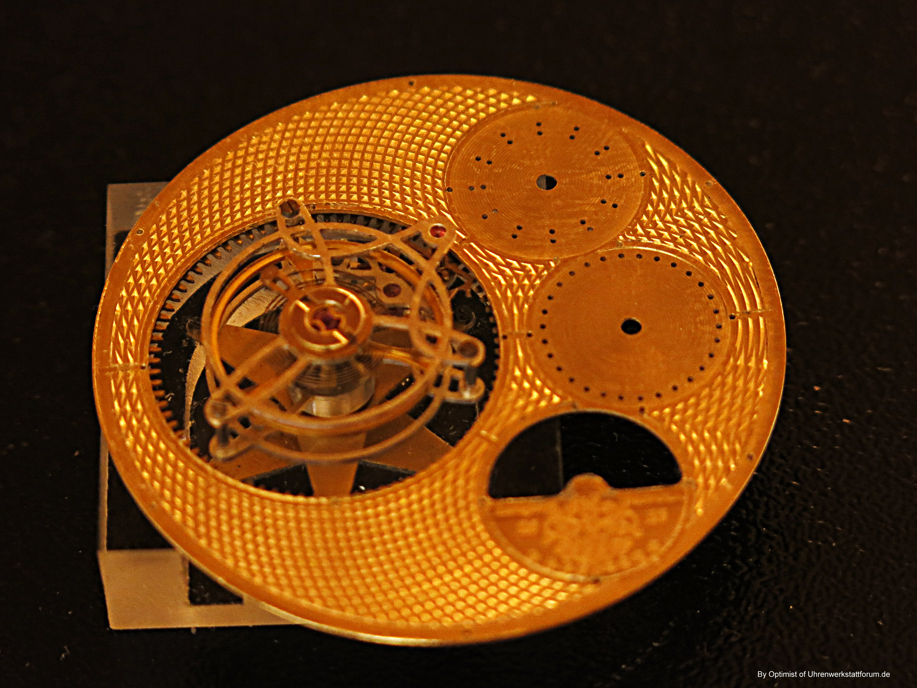
There is much more “material” left but too much of the same kind might be boring…
This is done in similar way but not from Aircraft grade aluminium but from cold working steel. Conceptual design… too heavy…

Very fancy parts can be done same way, routed half way from stock then refilled with CA (activated with mild tenside as it is an anaerobe adhesive which needs initators to crystallize on)
The dashes have a width of appr 0.08mm the screwhole is 0.5mm still embedded in CA to be dissolved
2 Likes
Getting closer to today … When buying my Ramps board for my 3D Printer I thought the boards were so cheap that I had to take 2 sets… thinkering about whatfore to use the second set I decided to do something beside p
rinting


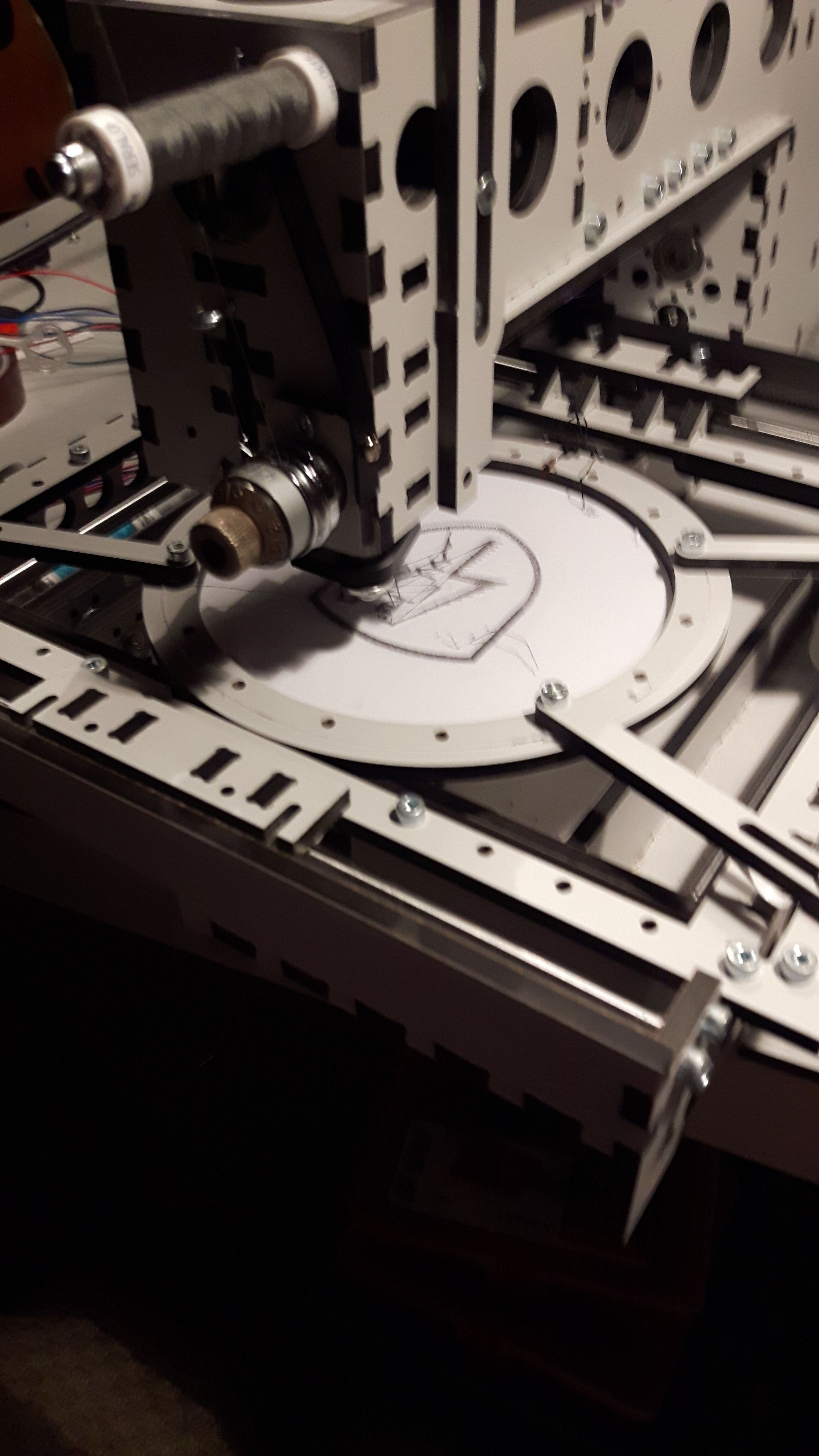
2 Likes
I think I now should break the timeline as we are close to status quo, - but not to bore you I left out many projects over the time…
3 Likes
Recently: as I have told, I’m currently digging into watchmaking.
The latest challenge are two vintage quarz watches with defective coils of the lavette stepper motors.
Unfortunately those coils are wound with 0.02mm
enamel wire which is not possible to be wound by hand. At least not by n= 1800 .
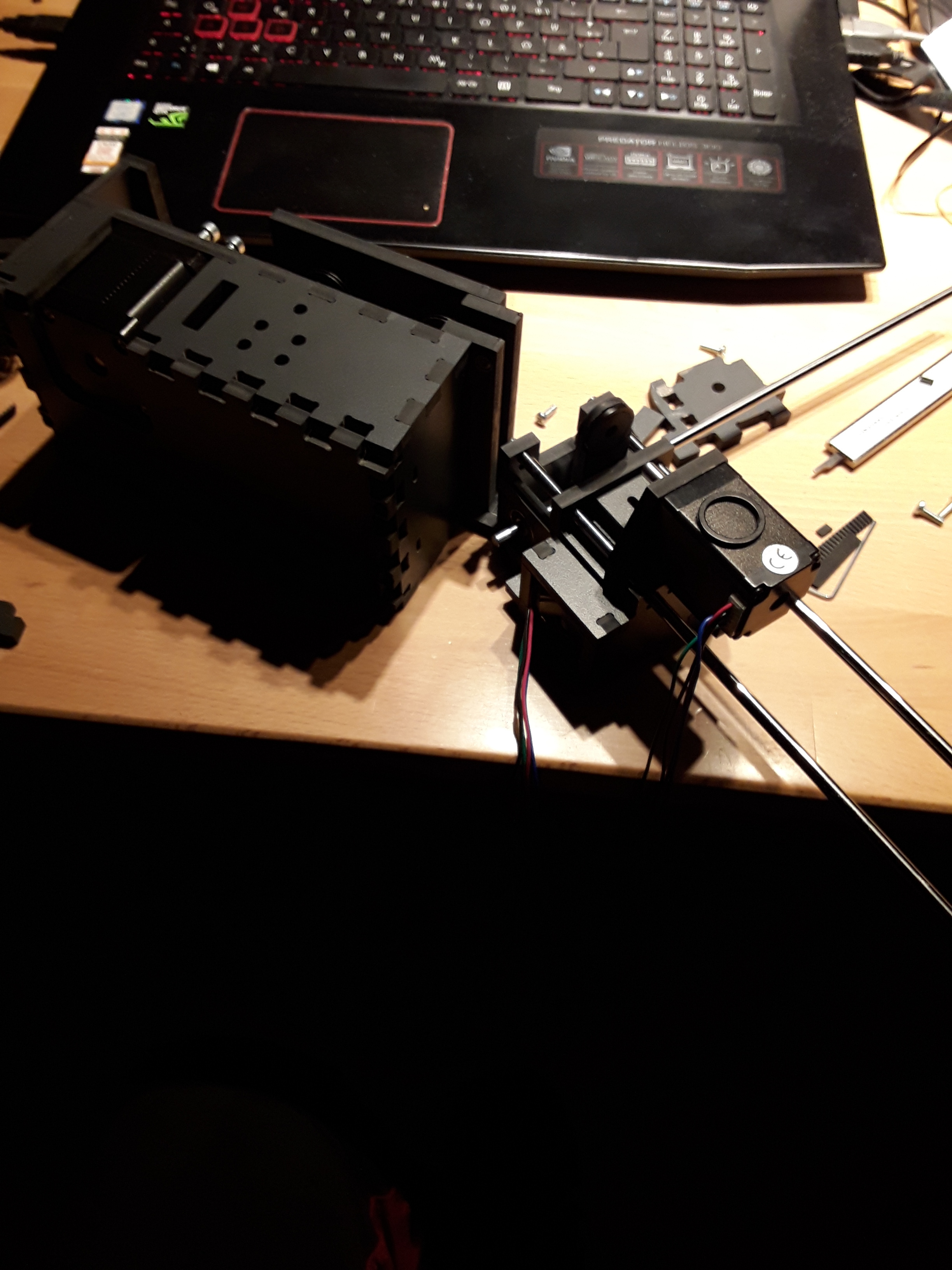
So I started buliding a coil winder…

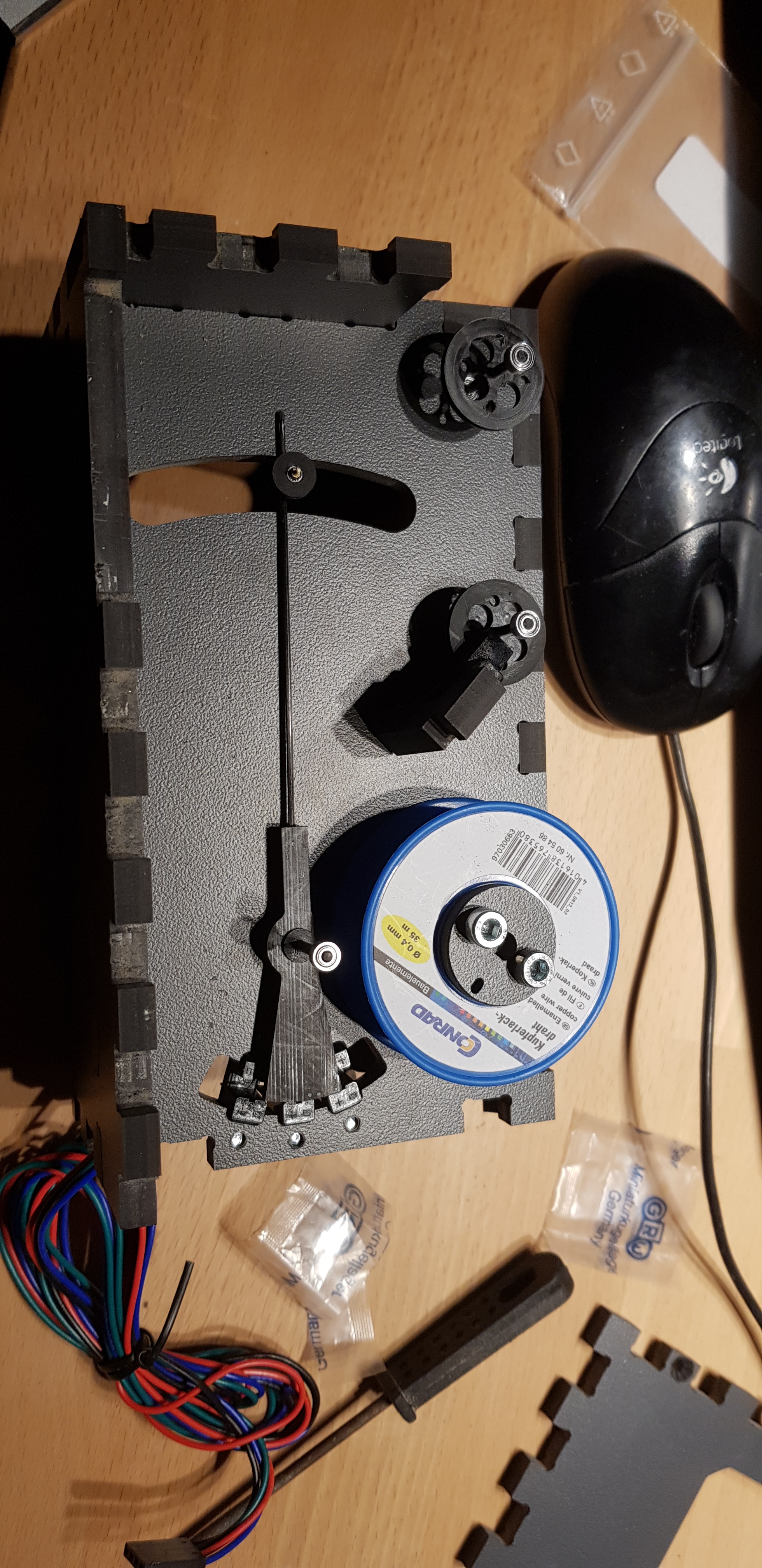
First part is the wire auto support with someway a constant tension source.
( until now ist just mechanics but the uc boards should arrive by next week)
5 Likes