I’m just messing around with theoretical stuff at this point, but is it possible to change the projection plane for 2D objects? I was playing with some of the 5 axis machines and trying to find a way to do projection on STL with those, but it seems that 2D objects can only be in the XY plane?
can you post a picture maybe of what you are looking for?
You can project a 2d object onto a plane and then move/deform the plane in 3d and get a different projection/object but this maybe different than what you are talking about.
Are you talking about grey scale height maps?
At this point I am just looking to do projected cuts on an STL using a 5-axis machine. As an example, if I open up the Hybrid5D machine, load a cylinder STL, and then load a DXF that I would like to put on the cylinder. The 2D object is opened in XY plane, but in order to get it on the side of the cylinder it would need to be in XZ or YZ planes.
Unfortunately, even with 4-axis machines I seem unable to select projection on STL cuts. It isn’t present in the cut menu, even when I have the 2D object positioned as indicated in the feature youtube videos.

I see. So its more a question of the software capability. Sorry, I will not be able to assist. I am the most ignorant person on here for cam software. Hopefully someone can help on here. They are super smart.
Not sure if it would be useful but on the question of 2d plane projection to 3d it can be done externally in 3d modeling software (used Blender3d) and then exported to STL.
For an example below.
I projected a 2d image (height map image) onto a plane
Displaced the height data to get the 2.5d model
Deformed the plane to a cylinder and closed the ends
I can export the model to STL now.
Good luck.
2 Likes
I started with CAM functionality on the 3-axis and am slowly struggling along. ![]()
Unfortunately, I don’t have the multi-axis machines under control yet as I would like. Not everything is working flawlessly yet.
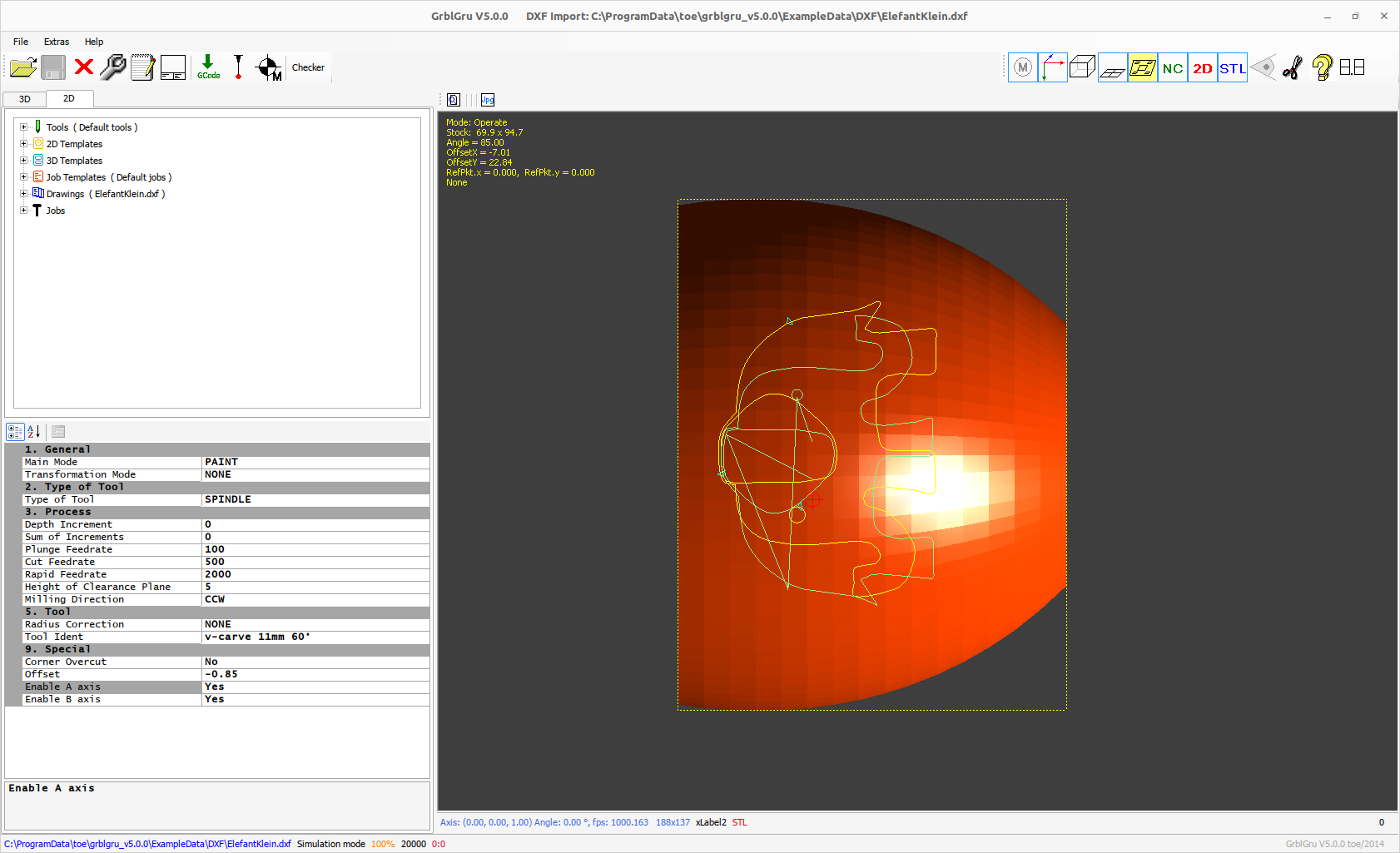
If I understood your question correctly, you want to project the DXF drawing onto the side of the STL.
The projection is always from top to bottom, i.e. in Z-direction. But you can change the position of the STL.
Press CTRL AND the left mouse button to select the STL. The STL gets a dashed frame.
Now you can open the 3D Context Menu with CTRL AND a right mouse click. Select ‘Geometry Editor’ and rotate the object with e.g. delta x to rotate the object by 90°.
Now position the tool in the 3D view approximately above the STL and press “Set Workpiece Zero Point”.
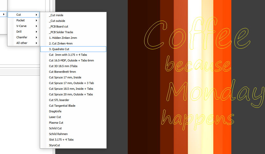
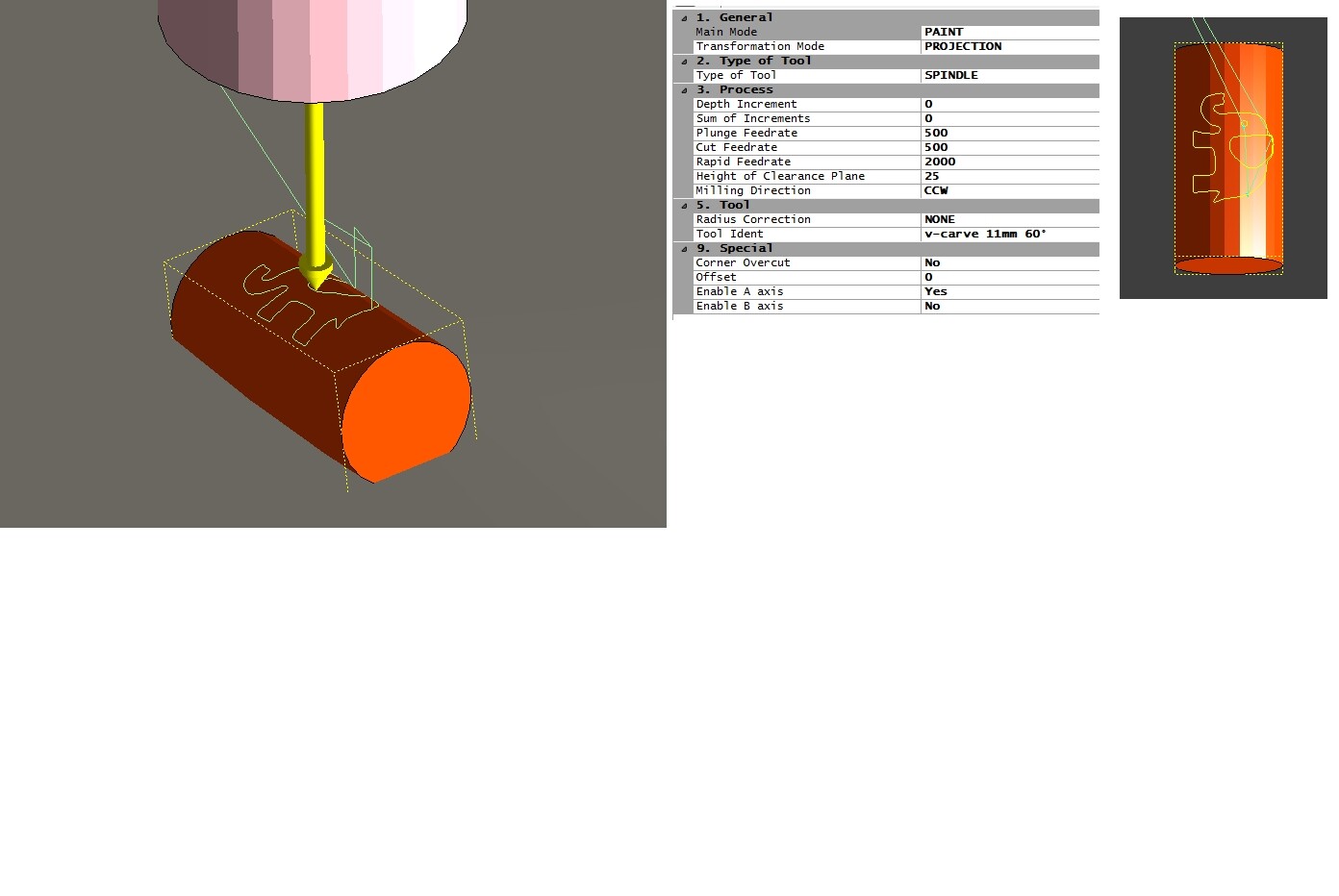
Go to the 2D view and select the paths of your drawing. Press the right mouse button (without CTRL) to open the 2D context menu. Select ‘Graphic Editor’ and position your DXF exactly over your STL. Now create a job “Paint + PROJECTION”.
Please have a look at my website. At Video Gallery you will find the videos “Scanning uneven surfaces and turned parts” and “Ring Engraving” as examples for handling
of DXF and STL.
Please let me know if something should not work.

3 Likes
Thank you, that was very helpful. I have made some progress, but one issue which I am running into is that even if I enable A and B axes for a 5 axis machine, they do not seem to be used. The system I have in mind would have a fixed Y axis, so I am trying to eliminate Y movements. This includes using stock machine definitions. The only one that seems to work for me (so far) is DIYCNCEngraver.
As already mentioned, not all multi-axis machines work yet. If you can describe your real machine and explain what exactly you want to do, I can try to find a solution.
Thank you. I appreciate the support (and all the work that has already gone into GrblGru!)
The machine I am trying to build is effectively a “bolt-on” 5-axis for my wood lathe. A axis is the lathe spindle, with an X, Z, and tools on a B axis. I have been able to get it to work to some extent, starting with the DIYCNC-Engraver and doing some very basic stl mock ups. In my case the tool (B axis) would physically be mounted on the X axis, but I’ve found that GG defaults to putting tools on Z, so it doesn’t look pretty, but works:
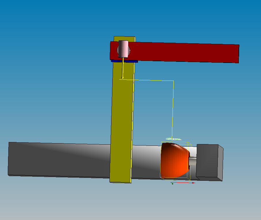
With this setup I have been able to get A and B axes working, though because my A axis setting is X=-1, any projections are inverted:
I suppose this is related to how the coordinate axes are established in the machine definition.
I’ve also played around with trying to do cylinder projects and that leads to tool paths being placed at weird locations (that are not impacted by radius setting of the stock). I haven’t probed around much with that yet.
You have already been very involved with GrblGru ! I would like to exchange with you about it.
I have sent you a PM with my email address. Maybe this way we can exchange files easier. If you agree, please send me the STLs of your model.
1 Like