Sorry, off topic. What’s this about dissolving a drill bit?
1 Like
Interesting. I see a number of references like this one from hackaday.
Seems clock makers are in the know. Any experience @funinthefalls?
So alum is ammonium aluminum sulfate. Aluminum sulfate will react with iron. I think using alum is just because it commonly available. Just Aluminum sulfate, with out the ammonia would probably be more effective as you are making sulfuric acid to attack the iron. The aluminum part, the drill bit is in, is passivated so does not readily react.
2 Likes
This alum is labelled as potassium aluminum sulfate. @NedMan would you expect that to be better or worse than ammonium aluminum sulfate?
It definitely didn’t work in 30 minutes. It’s still cooking. It’s much better than it was, but I can’t cook it overnight. Maybe just leave it in there and turn the stove back on in the morning.
Oh, I see. Hmm…I don’t think there would be much difference between potassium and ammonium based alums as far as dissolving steel.
2 Likes
Next time I’ll use a crock pot overnight, and a different container that I can put the whole part into. The surface was damaged slightly where it stuck out of the water, and turning off the stove for the night precipitated alum onto the surface of the glass inner vessel that I haven’t completely removed. Some alum escaped the glass vessel and I had lots of work to do with scotchbrite to fix the saucepot. Took a bit of work with emery cloth and scotchbrite on the bracked to make it look presentable.
I filled the belt clamp mounting holes with jb weld, and tomorrow or so I’ll drill new holes in the right place.
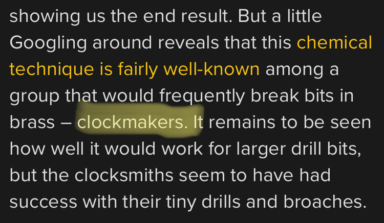
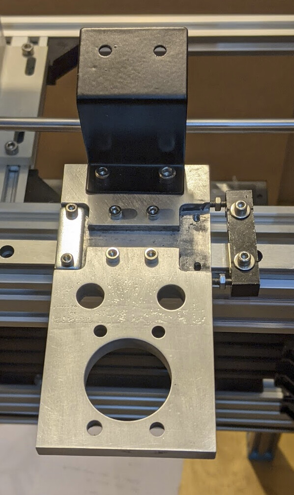
Here it is, test-mounted on the linear rail:
1 Like
So you ended up dissolving out the bit?
Mostly. There was junk left in the hole, so when I tapped it, it turned out rather loose. However, I don’t actually know what that hole is intended for; I was just copying the part and figured if it were important later it would be nice to have it already done. And I was curious to do the experiment on a part that didn’t matter very much; worse case I could make another one. It has enough features that it’s a little tedious, but it’s not hard work.
1 Like
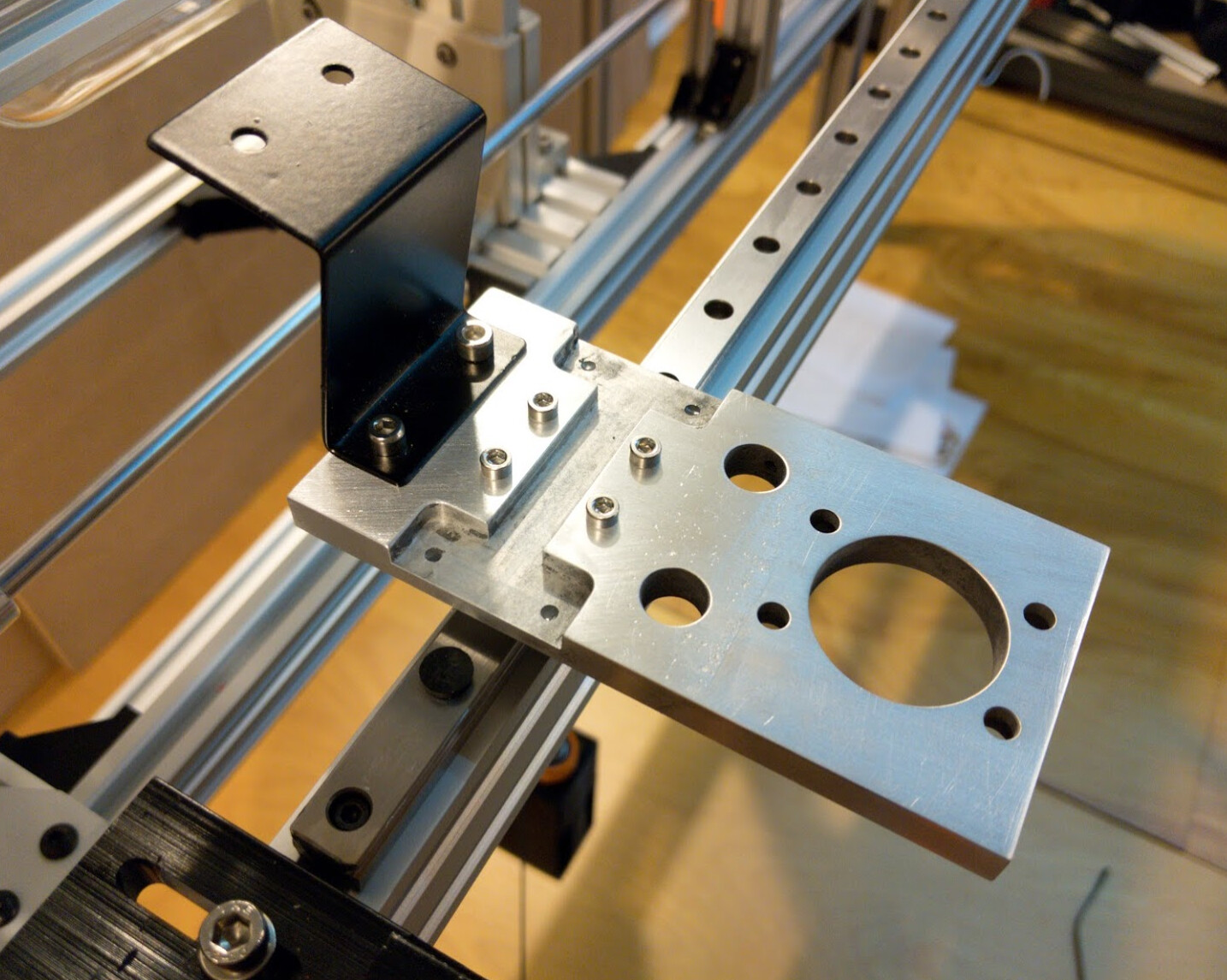
Filling in the tapped holes with JB Weld, letting it cure, and redrilling and tapping worked well. Here’s the usual blurry cell camera picture that shows the overlap.
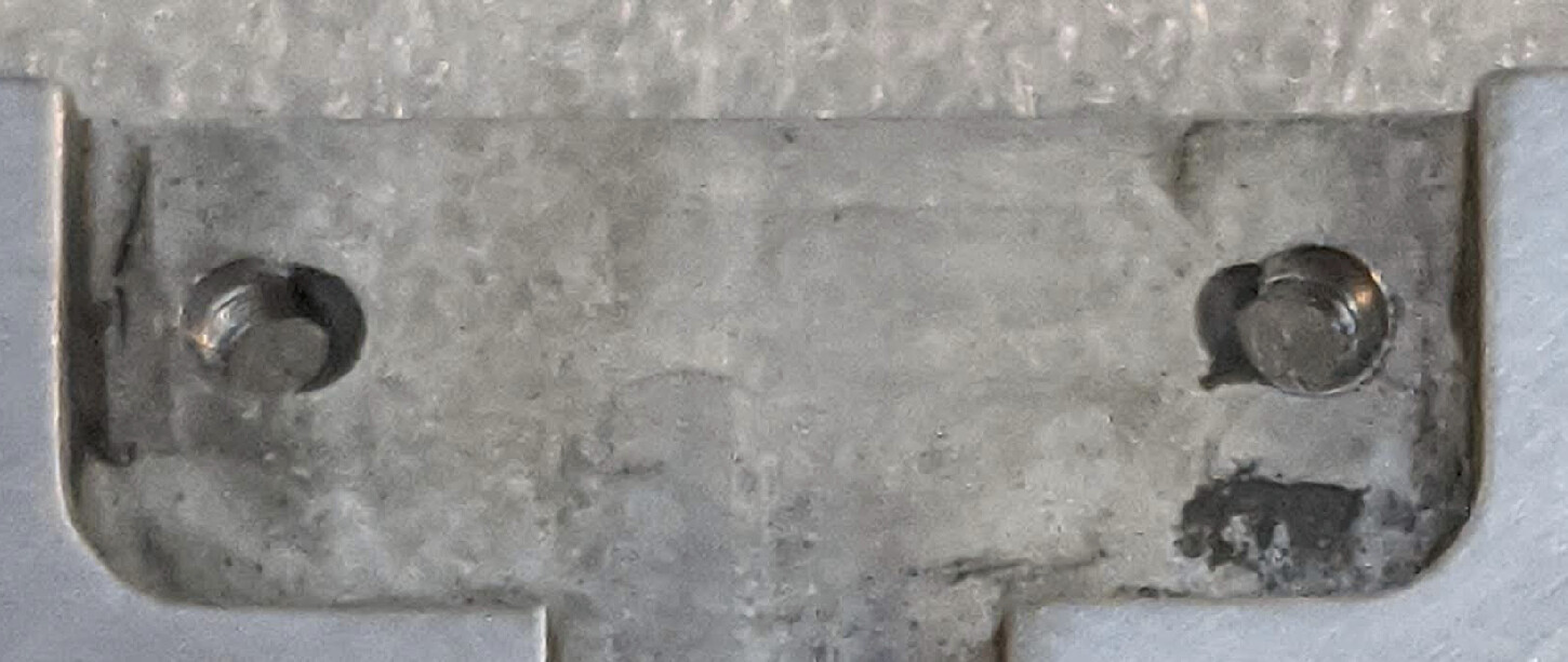
Here it is with the hardware attached:
Installed on top of the rail, now moved to the top of the gantry:
After all that work, I realized that moving the belt to the top was going to cost me some X and Y travel. So instead I’m first trying to use the belt position I came up with initially. I’ll drill two more holes for M4 screws to attach a belt fixture. A typical 40mm x 9mm belt clamp screws into the bottom, holding the belt in place. (This part could still be 3D printed trivially enough, but I’m going to use the mill.) The cut-out at the top goes around the carriage.
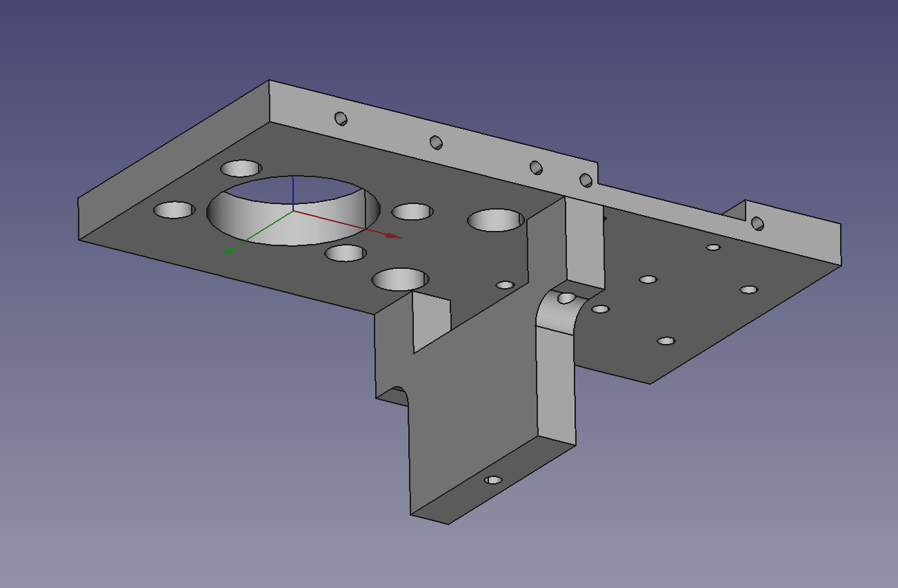
The new design, done with the latest realthunder build of freecad, is pushed to the repository. I haven’t cut it yet.
4 Likes
I mis-measured something, so I drilled the mounting holes in the laser head block such that the belt block piece was 2mm too close to the laser tube.
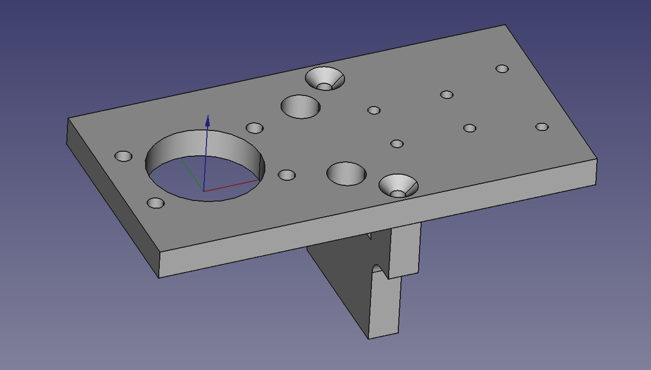
I’m going to leave the current block for if I ever decide to run the belt on top as is often done (using the belt clamp fixtures that came with the original block) and just make a new plate without the top belt groove and belt clamp holes for my current belt setup that looks more space-efficient:
Here’s my print, such as it is (if you know what you are doing, sorry if your eyes bleed when you look at my prints):
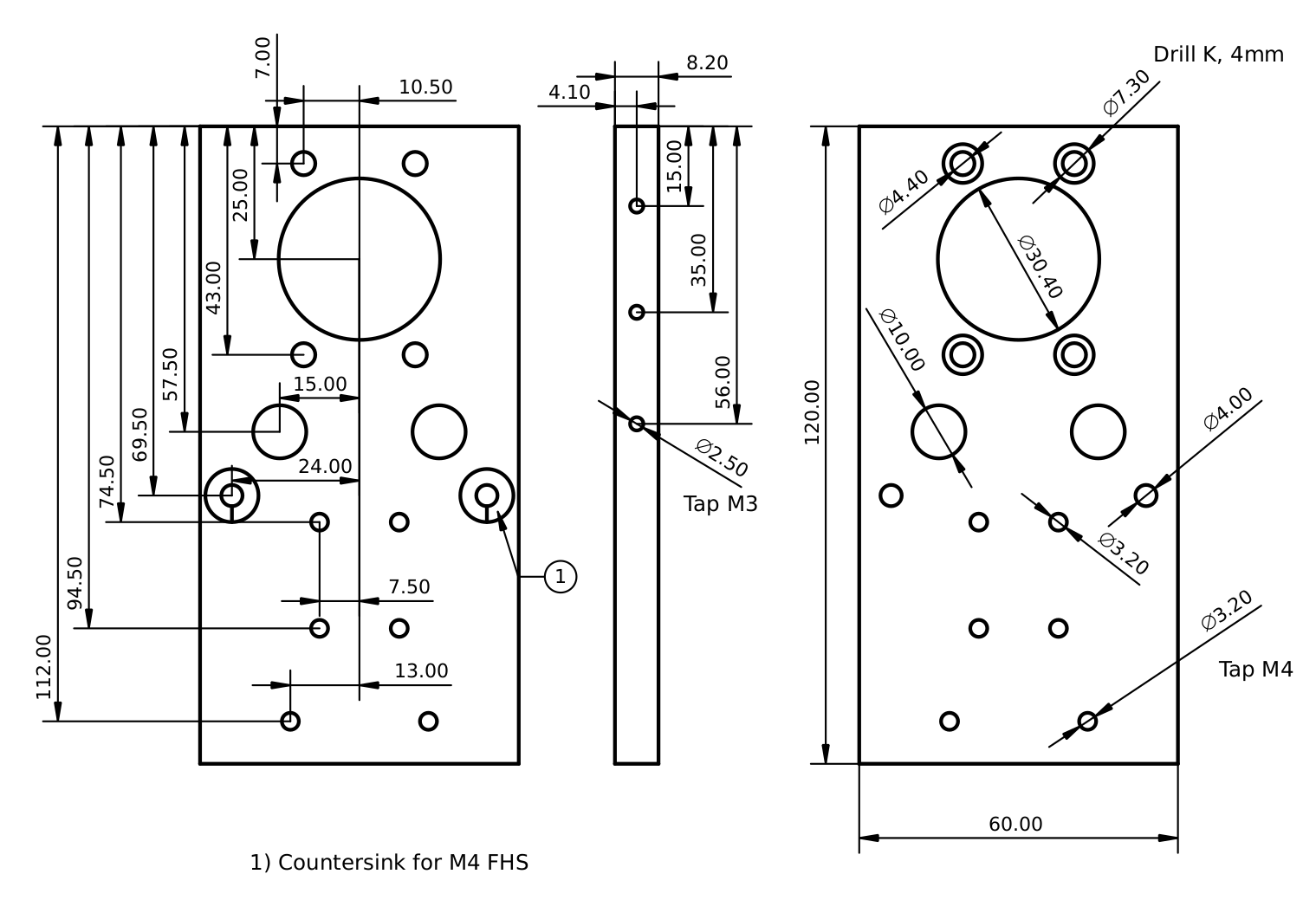
Edit: updated print for latest changes; one actual change in dimension, and a few missing dimensions and annotations added to the print, after making the latest version.
3 Likes