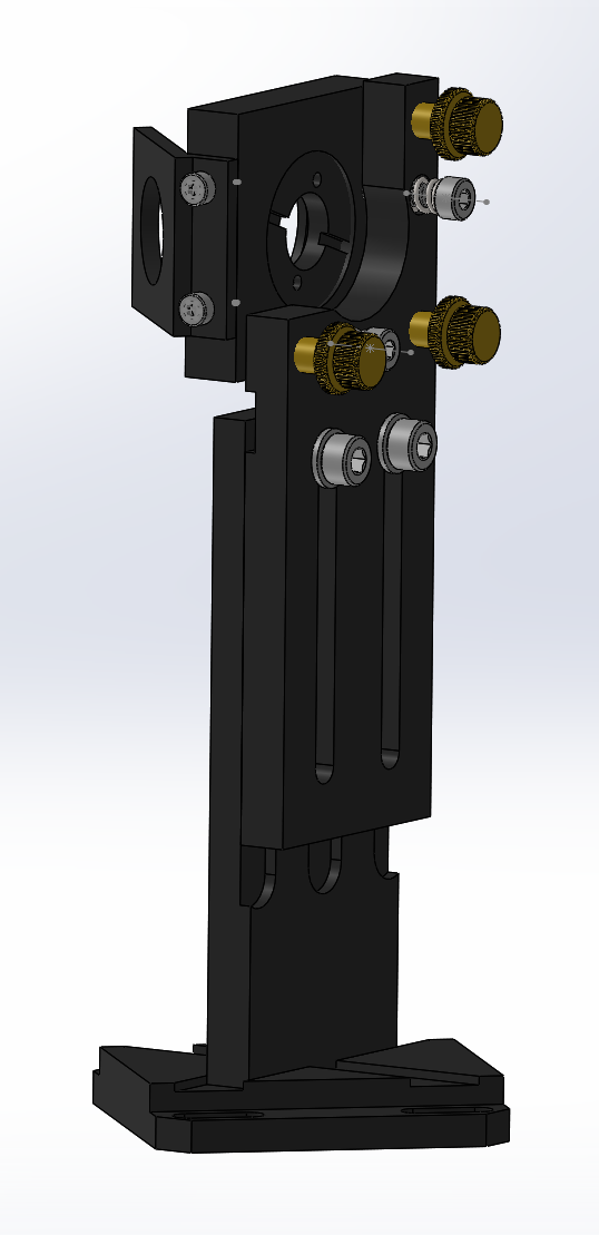
The current Project Monocle work is creating a CAD model of the Cloudray Series C laser mirror and head set. My youngest and I have been working with calipers and micrometer to create measurements, though we probably want to adjust them to the nominal dimensions I see on their site for the dimensions that they give, rather than the measured dimensions, since I expect that their dimensions drive the CAM and if our models match the nominal dimensions instead of our measured exemplar, our models will be more useful for others. We’re doing this as a SolidWorks learning exercise, but will export in multiple formats when we finish. Since we do just a few features per session, it will take a while, but I guess there’s no real hurry!
If you have SolidWorks 2019-2020, you can follow along at
I’m very much new to this and have made plenty of mistakes, but I think that it’s roughly right. Note that it’s designed to test fit in CAD, not to reproduce the design; I haven’t modeled any threads, for example.
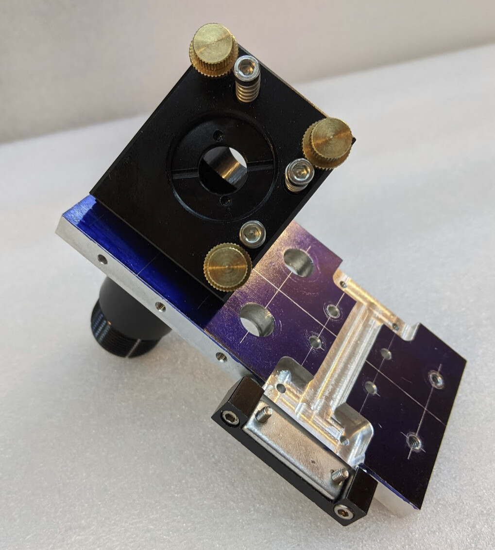
I didn’t notice until after I was looking at the picture to compare that I’d forgotten to put one of the screws back in! Other than being different projections, they look pretty similar.
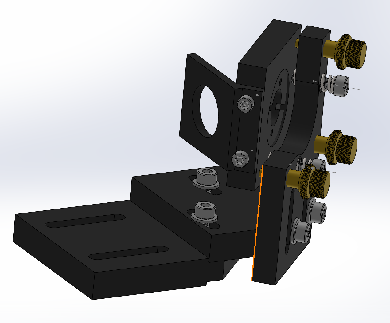
Here’s the second stage mirror assembly. Shares most of the parts with the first stage, but one part is shorter and has different slots, and the other two parts are utterly different. But I started with a copy of the first mirror, and changed the parts, so it’s basically the same design tree. Again, this model is good enough to use to validate fit in a model; not for manufacturing.
The laser head will be substantially more challenging to model.
Through this modeling work, I learned about the M6x0.5 screw pitch. At least, I believe this we have correctly identified what they use for the kinematic mount roll/pitch/yaw adjustments for the mirrors. It’s the first time in recent memory that I’ve run into a screw pitch that I don’t find on McMaster! But I can still find M6x0.5mm tap and die on Amazon with Prime shipping. If I ever am doing another kinematic mount for a 3D printer, this is an attractive option.
The dimensions on their drawings are manifestly wrong in places, to the point of being impossible. So we can use them as an expression of intent of something but not take them too literally.
I can’t find the roll/pitch/yaw adjustment screws for sale anywhere. It’s hard to believe that they are really a custom CNC part for only these laser heads; feels more like I am just failing on search terms to find them offered for sale somewhere.
I guess I’d better not damage the threads on them while taking this apart and putting it together over and over again.
Other than modeling the kinematic reference screws and locking nuts, and adding standard screw/spring hardware, we have an assembled model of the first mirror set.
Updated the OP now with images of the first and second mirror assemblies. If anyone is interested in playing with models while this is still WIP, let me know.
Did a good bit of the laser head tonight. The mirror stage, angle block, tube components down to the nozzle (not including the air attachment) are modeled and pushed to the git repository. No threads modeled, and I didn’t bother with the internal lens holder for now. Still have the bracket to model, though there I’m less motivated because I think I need to make a different bracket to match the linear rail I’m using.
I really want to get this finished soon so that I can pull it into the overall model to make sure that the dimensions will work before I start cutting extrusion.
I haven’t modeled the bracket yet, and it’s hard to get excited about starting, because it’s not a good fit for the monocle. I should do it some time in December if I’m going to, though, before I might have to update to a new version of SolidWorks to keep using the academic license. (Not sure exactly how that works, just got a warning that I need to renew the academic licensing.)
In the meantime, I made an alternative bracket that is designed to print or machine. I’m starting with printing, but may well cut it out of aluminum later once the design is proven. Here it is, done with the realthunder branch of FreeCAD:
The 3D printed bracket isn’t as stable as I would like.
Also, I worked out that the intended linear rail for the cloudray C head is HGR15, because as far as I can tell it is the only type of linear rail that has M4 holes on a 26mm square. If I hadn’t already purchased MGN12 rail I would just use the bracket that came with the cloudray set, and if anyone follows after me here to make another monocle, that should be the norm. In fact, HGR15 rails can be bought for $90-$100 for two 1500mm sections with four carriages, which could be cut up and be enough rail for the whole thing as long as you don’t want more than about 700mm Y travel.
But since I already have different rail, I thought I’d use my measurements to make a replacement part with mounting holes appropriate for MGN12-C with 20mm x 15mm M3 mounting holes.
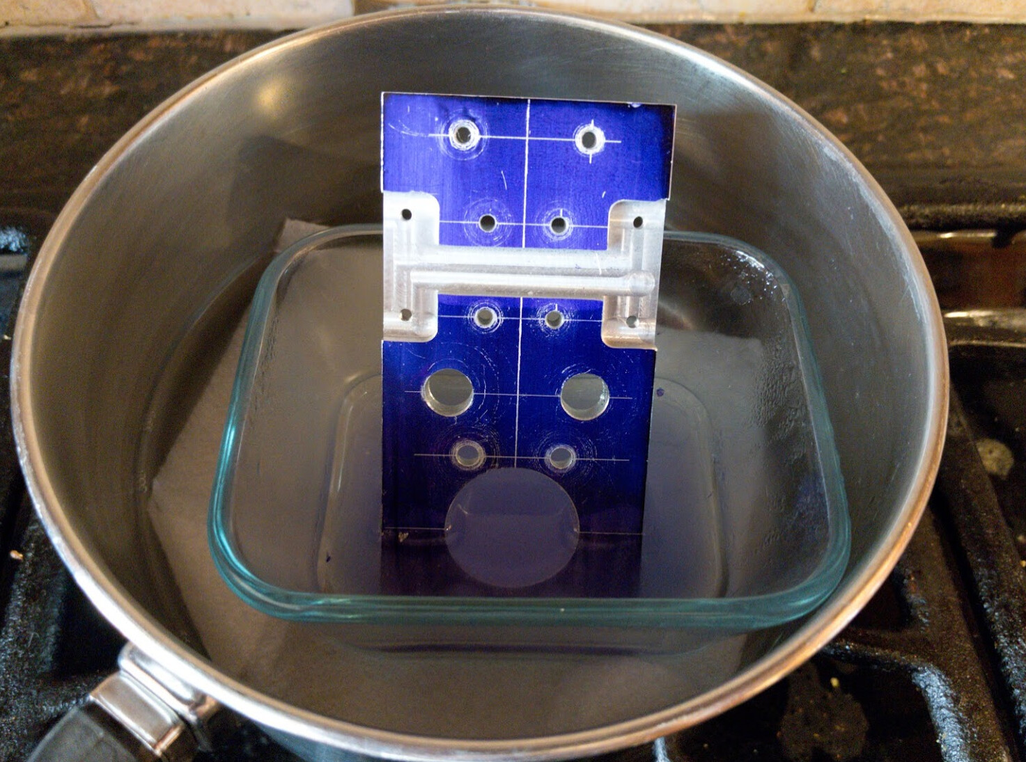
When I tried to assemble it, I discovered two small errors in the model; one was that the countersinks for the laser head mounting screws are slightly too deep, and the other was wrong screw spacing for the belt clamp — I’m not sure how I measured that wrong from the model, and at least I got the holes on the side for the belt tensioning clamp right. Washers will solve the too-deep countersink, and I can work around the belt clamp problem one way or another, maybe just making a new clamp using my mistaken measurements.
I also broke an old drill bit in one of the holes on the side, so now I’m boiling it in alum to dissolve the drill bit and finish the job: