Thought I would update the forum on the MOBeam build I worked on most of last week and this weekend. I have not completed detailed blog posts because there are still some details open loop.
I have completed implementing a few concepts that I had in mind.
Caution I have not completed testing these implementations.
MObeam is intended to be a shop tool like a router or jigsaw. To that end, I focused on its mobility with the ability to engrave on finished woodworks of various types and sizes including vessels turned on my wood lathe. I traded off automation for simplicity and at the expense of more manual adjustments.
A fundamental concept was to leave the laser diode module at a fixed focus and instead move the entire assembly up-down as needed to get the target in focus. Sound crazy?
The laser focus is set at 30mm [G8 lens] up from the bottom surface of the base plate. The entire assy or alternately just the movable bed is then adjusted up/down based on the thickness of the target. In a way setting up MObeam is similar to setting the bit depth on a wood router.
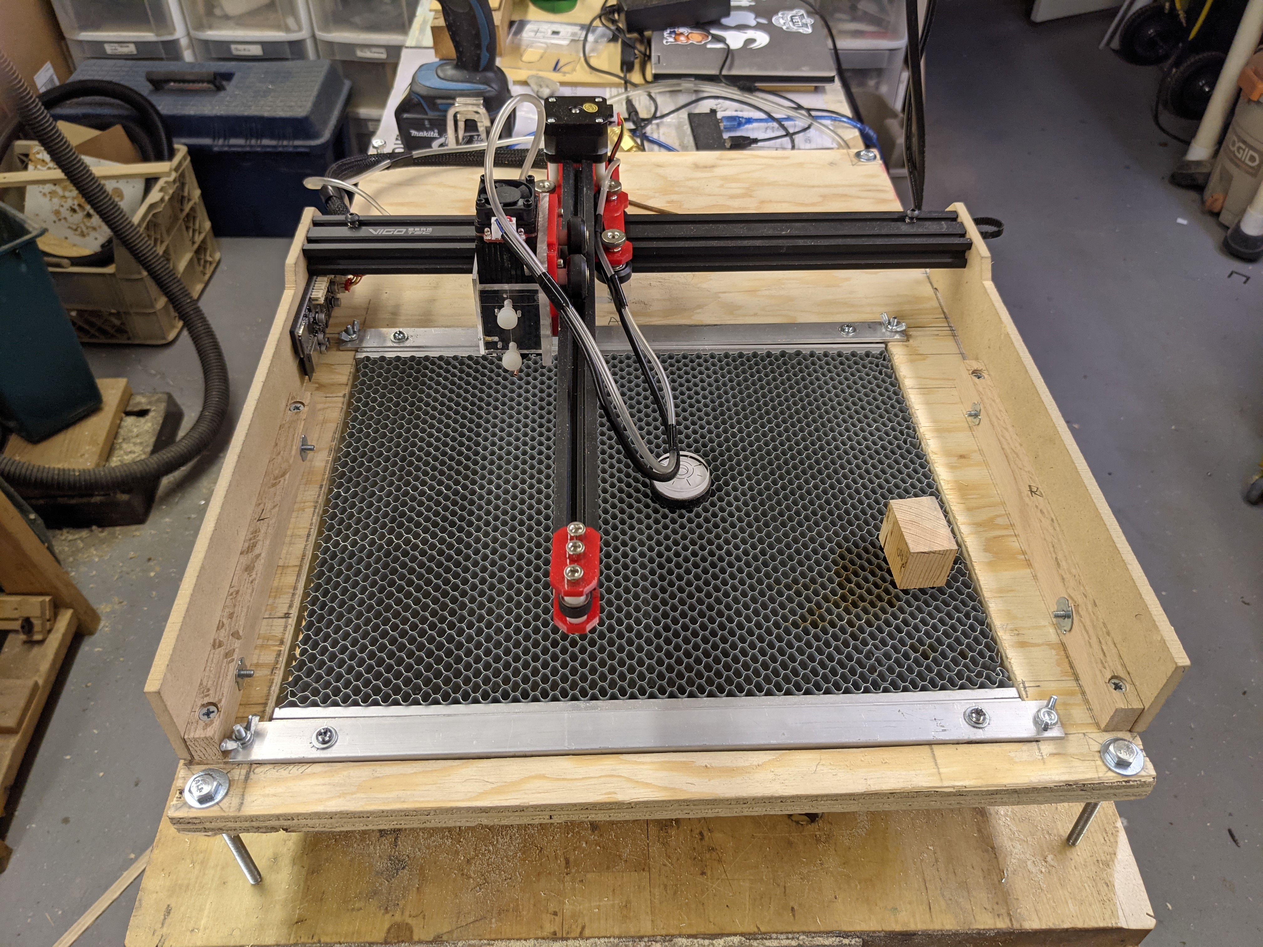
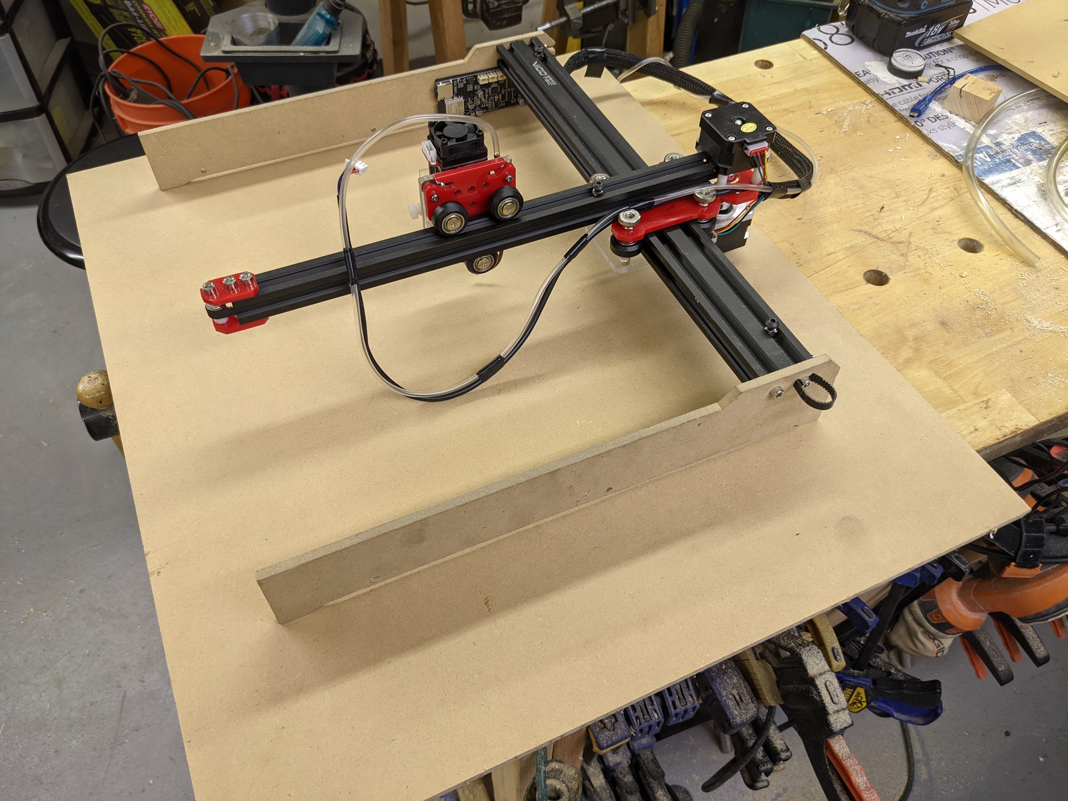
The laser module gantry assembly is mounted on a piece of 3/4" plywood into which an opening is cut. This opening is left open or alternately accommodates a moveable cutting bed [one I bought for my K40 and never used]. The entire assemblies distance the surface is adjustable with 4 1/4-20 bolts
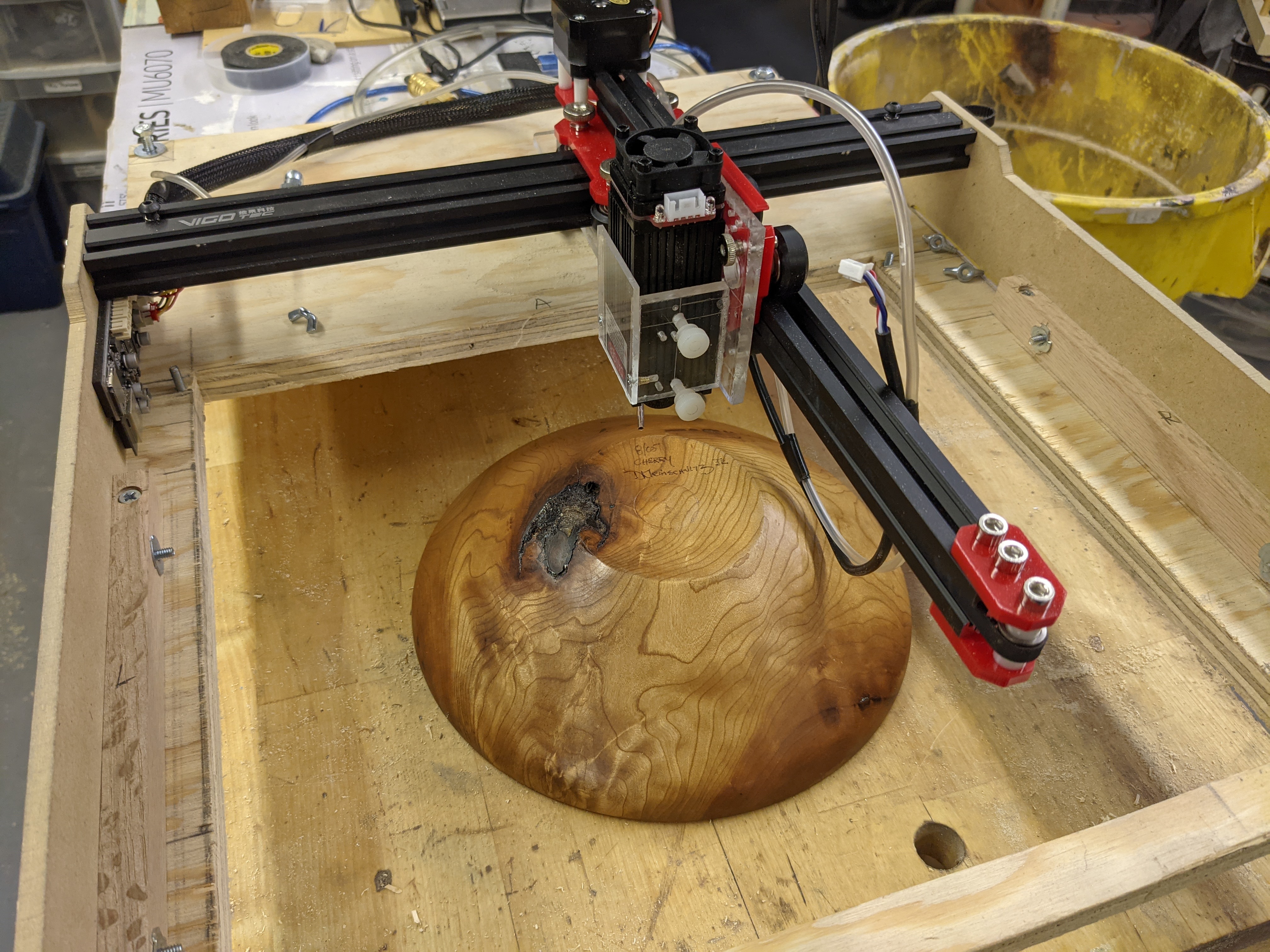
Very thick or odd shaped targets:
When left open the target is placed on the bench under MObeam and the entire assy is adjusted up/down with 4 legs until the target is parallel to the bottom of the base plate.
Small Flat Targets That Fit on the Cutting Bed
When the cutting bed is used it is mounted in the opening and 4 screws allow it to be adjusted until the target’s [laying on the bed] surface is parallel with the bottom of the base. The assy is mounted into the base plate with 4 thumbscrews. Adjustments are made with a 30mm gauge block.
Large Flat Work
If a larger flat material needs to be engraved [front of a chest] the gantry assy can be dismounted from the baseplate with 4 [thumb] screws removed from the side plates.
The gantry assy is placed flat on top of the target and no additional adjustment is needed.
Cheap Height Adjustments
Depth adjustments are done with a battery-powered drill and a gauge [not shown] that is the thickness of the base plate.
Laser Module Adjustments
The only time the module needs adjusting is if the lens is changed and then it is simply aligned to the bottom of the base plate.
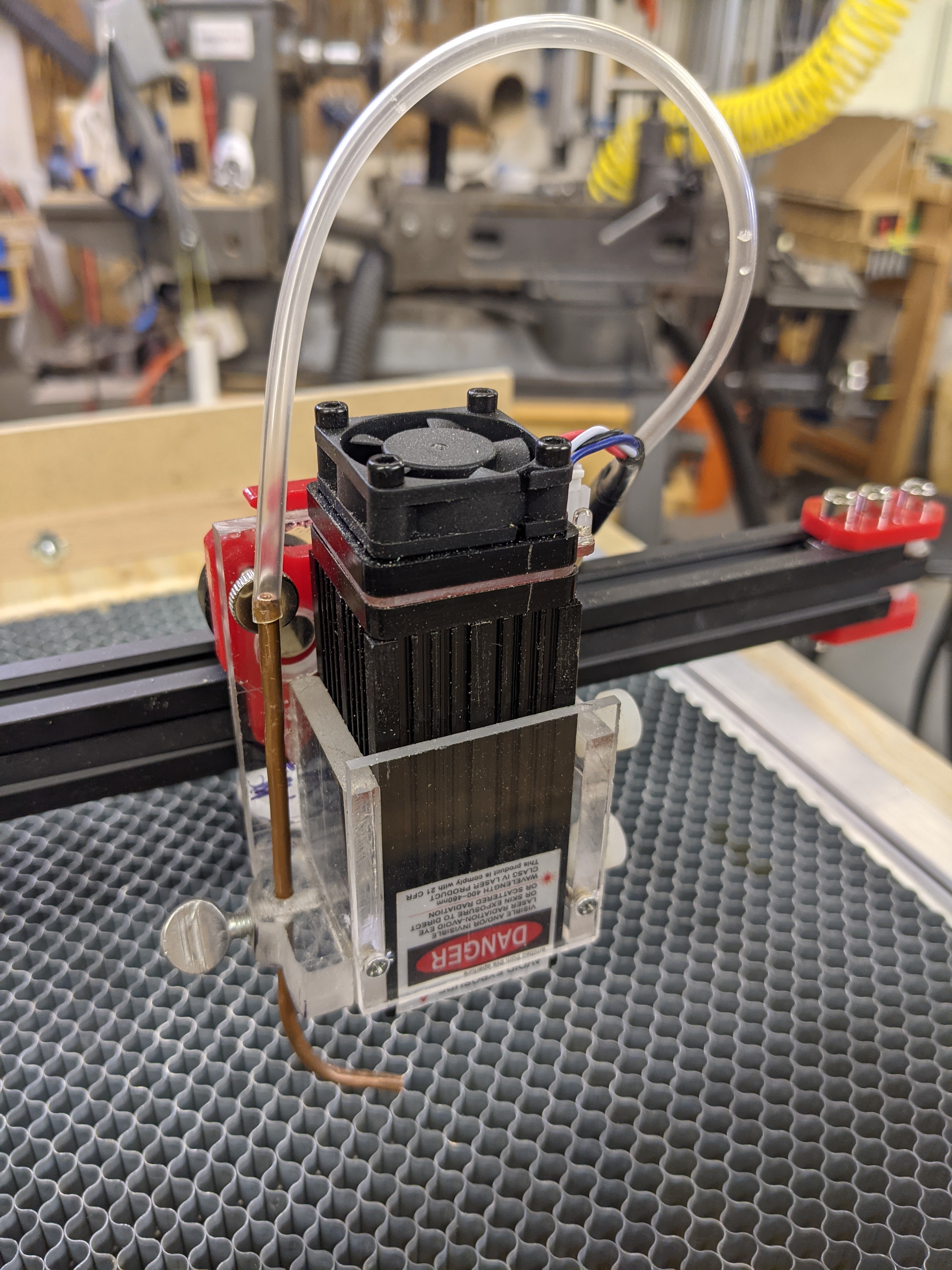
Current Laser Module Mounting
- The laser module mount had to be shortened once I found the correct FL.
- An air assist was added using some refer capillary tube [my wife thought I was nuts] I salvaged when we got a new HVAC last year. The feed tube is an IV tube saved from my recent hip replacement … Seriously I did that!
Cheap n Dirty Build Highlights
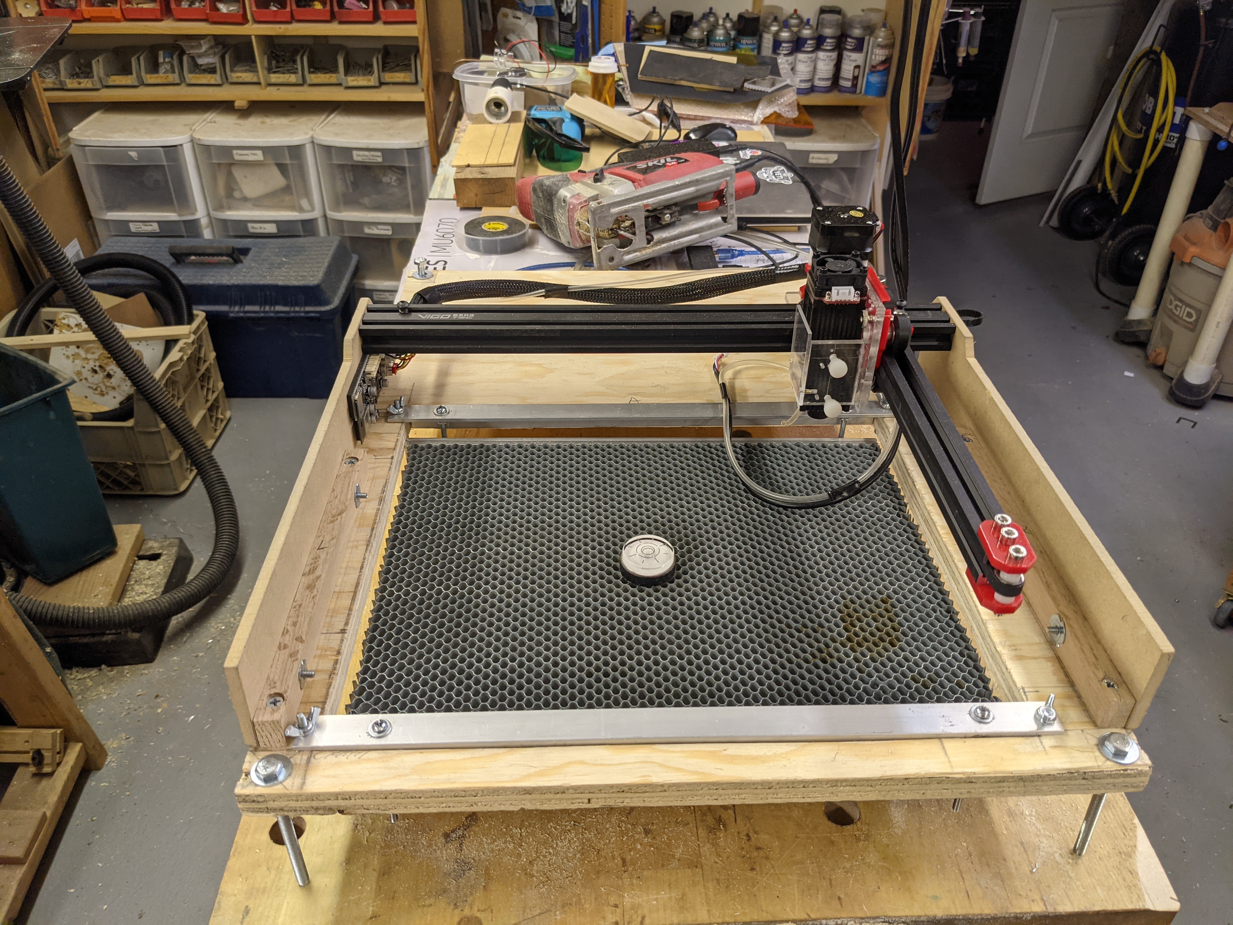
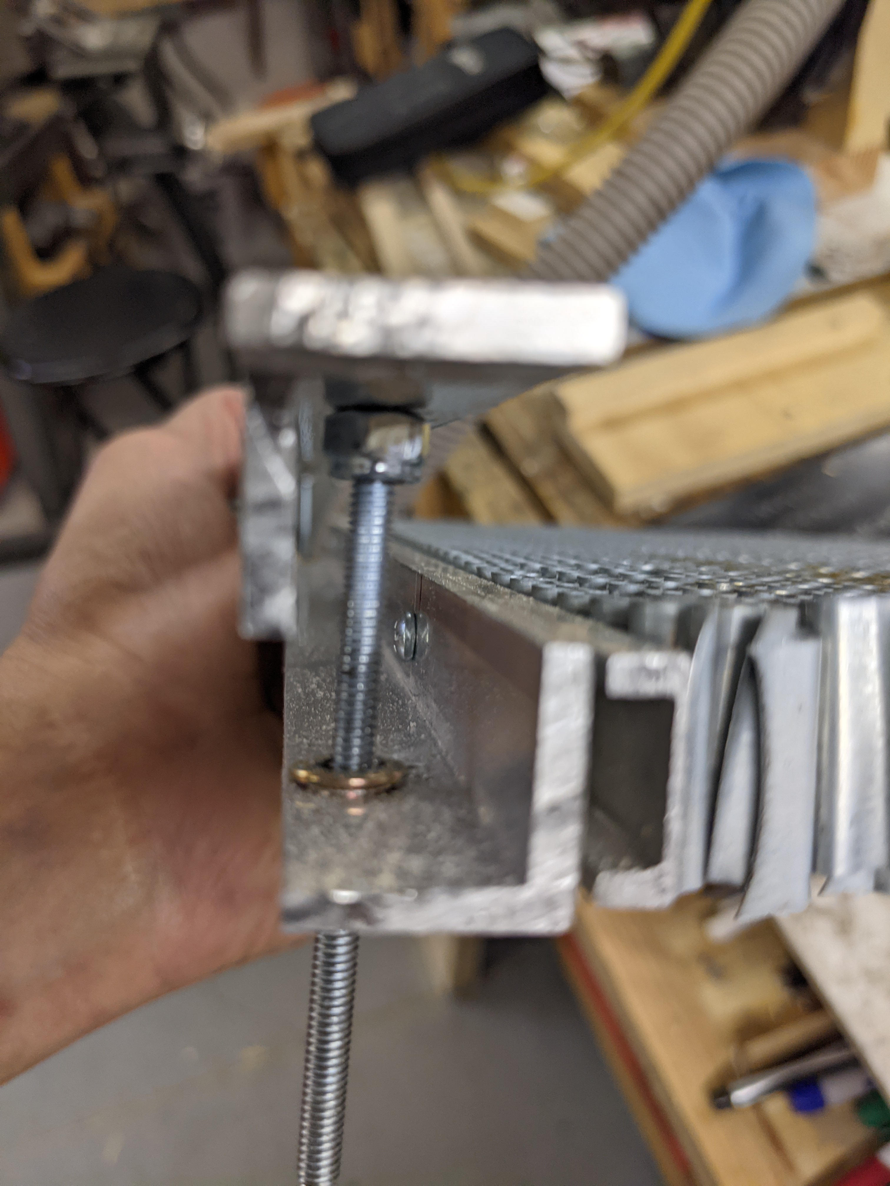
Views showing the adjustments for the base plate and cutting bed insert.
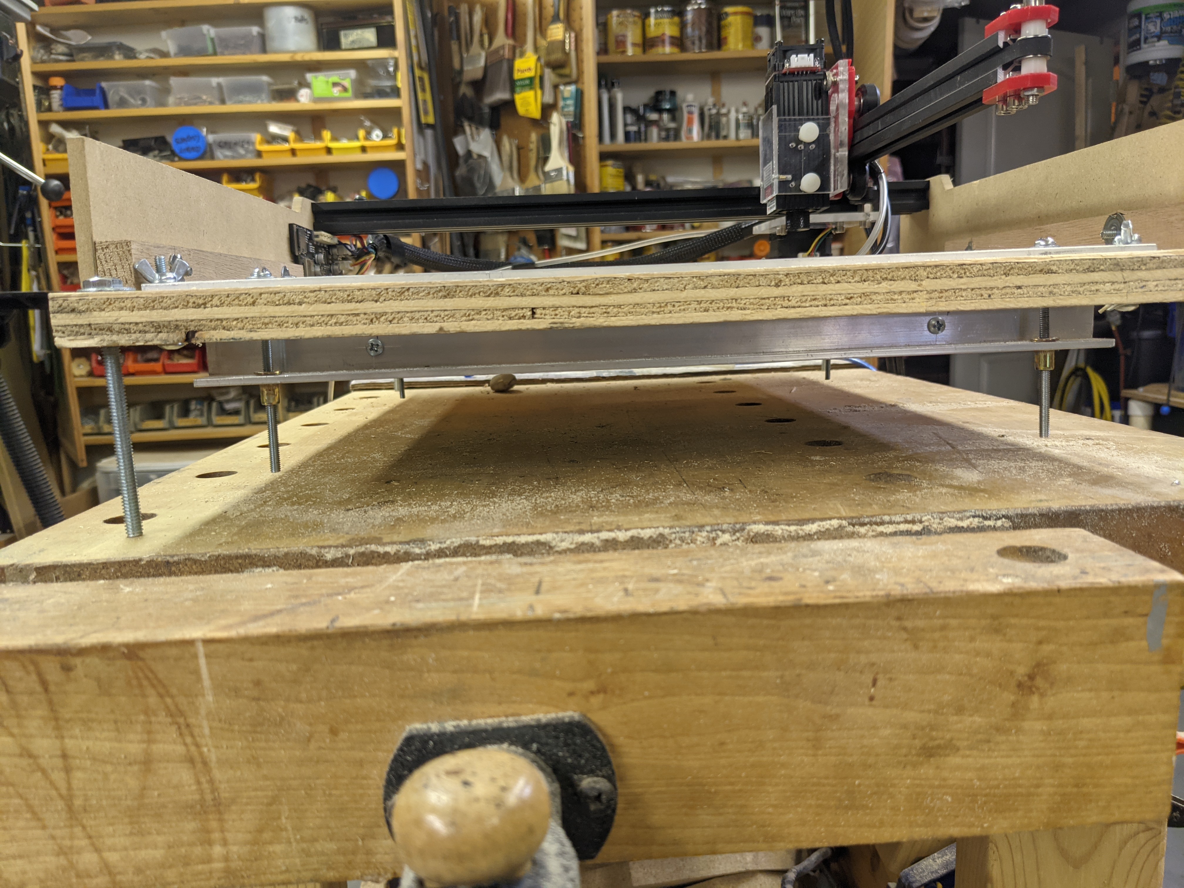
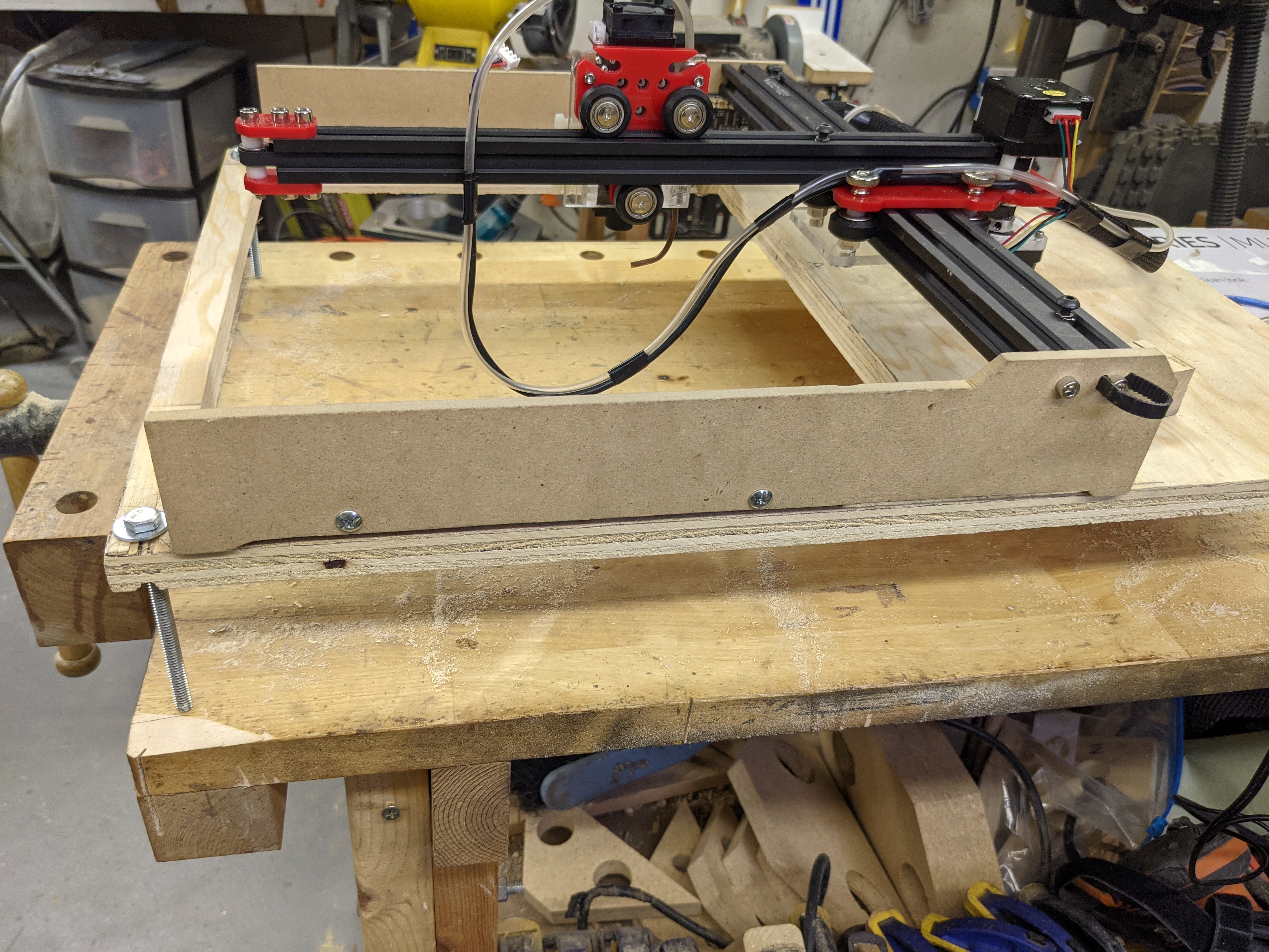
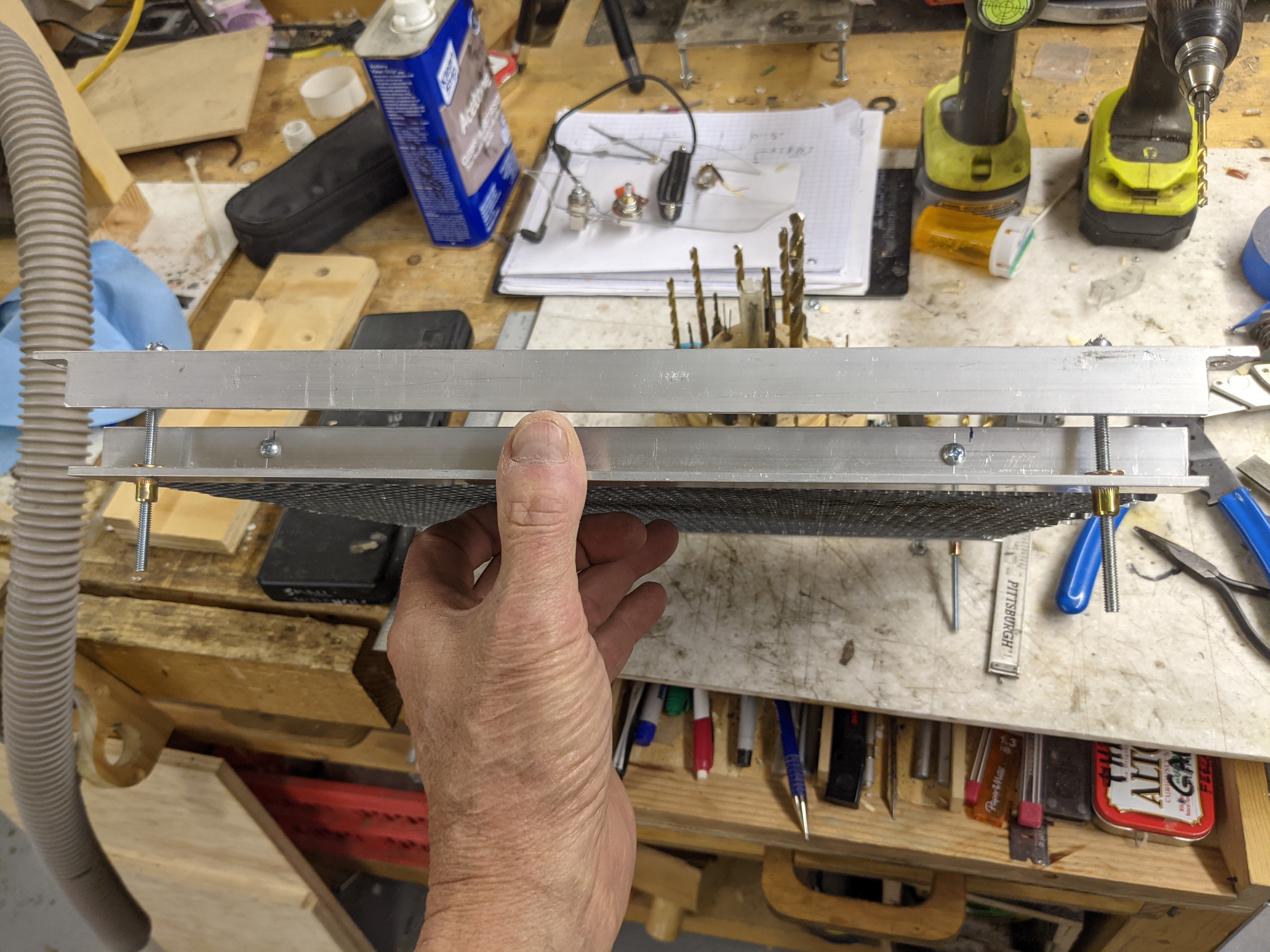
Detailed views of the bed adjustment mechanism.
Yes I know, I cringed when I started this design …
However this assy worked better than I expected. Then again I took a lot of care to ensure the holding bracket and the bed mounts were perfectly aligned. The adjustments [one screw at a time] were not as clunky and painstaking as I thought and it did not bind until I adjusted only one screw a ridiculous amount relative to the others.
Known problems:
- The nutserts in the lift bracket don’t like the thin AL angle and tend to come loose, a PEM nut would be better.
- The honeycomb bed is not really flat [never realized that] a thin perforated metal plate would be better.
Known Improvements/Adds & Before You Ask
- Tilt and lift interlocks on laser power
- Light shield on the laser module. I decided to shield the laser module, not the entire unit.
- Air evacuation. I am working on a plenum that slides under the baseplate.
- Filter: considering a canister filter design that uses the evac fan salvaged from my HVAC replacement
- Simpler laser and air assist mount now that I know it will not need to be adjusted often. This may also help in thermal management since the laser heat sync will not be captured.
- Thumbscrews and cap head on adjustment screws to prevent striping and the need for hand tools.
- Protective cover and handle for storage.
- The use of metal vs wood for the base plate would help with fastening and dimensional predictability but beam reflections would need to be considered.
- Taller Acrylic side plates for better stability.