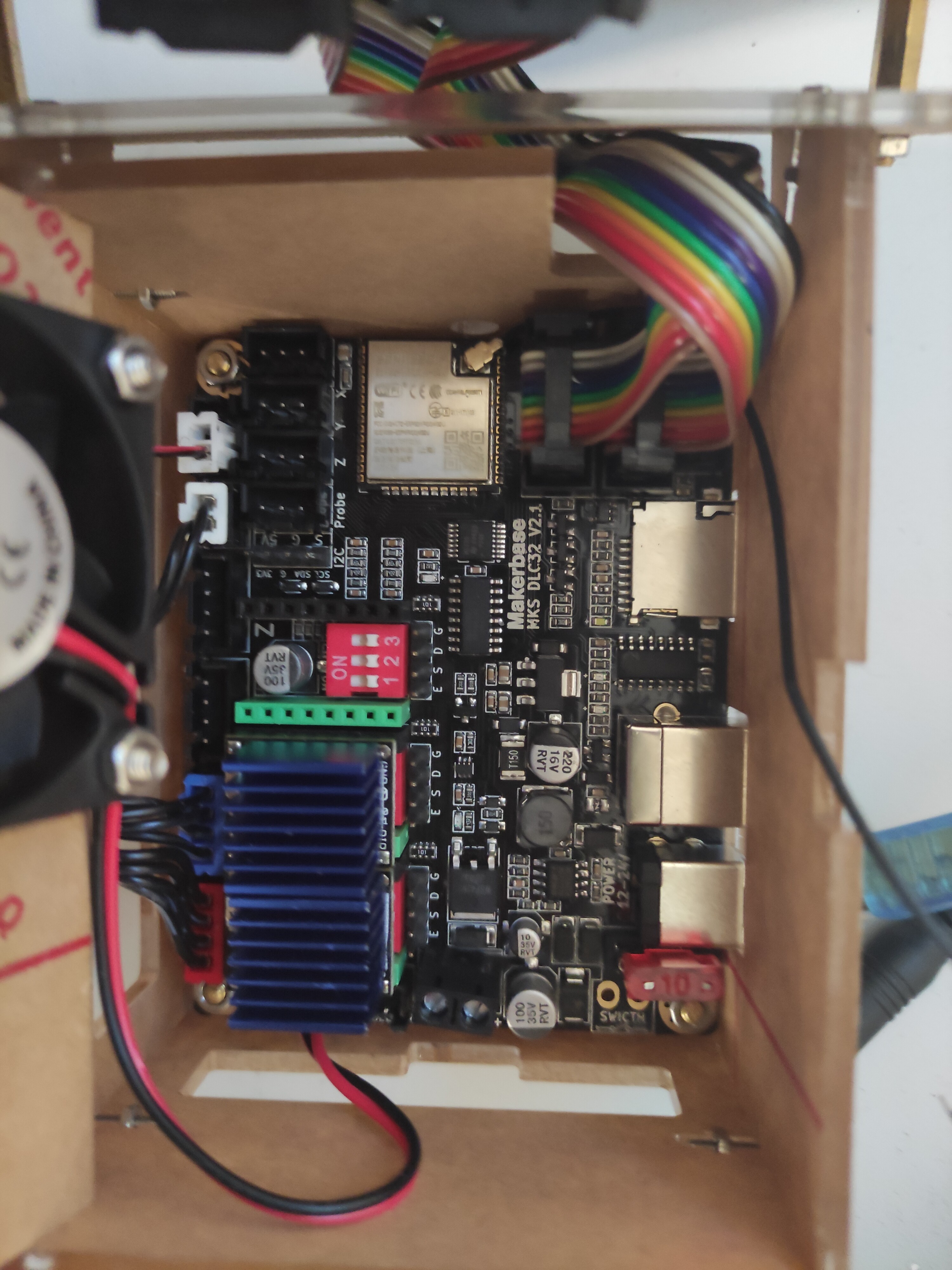
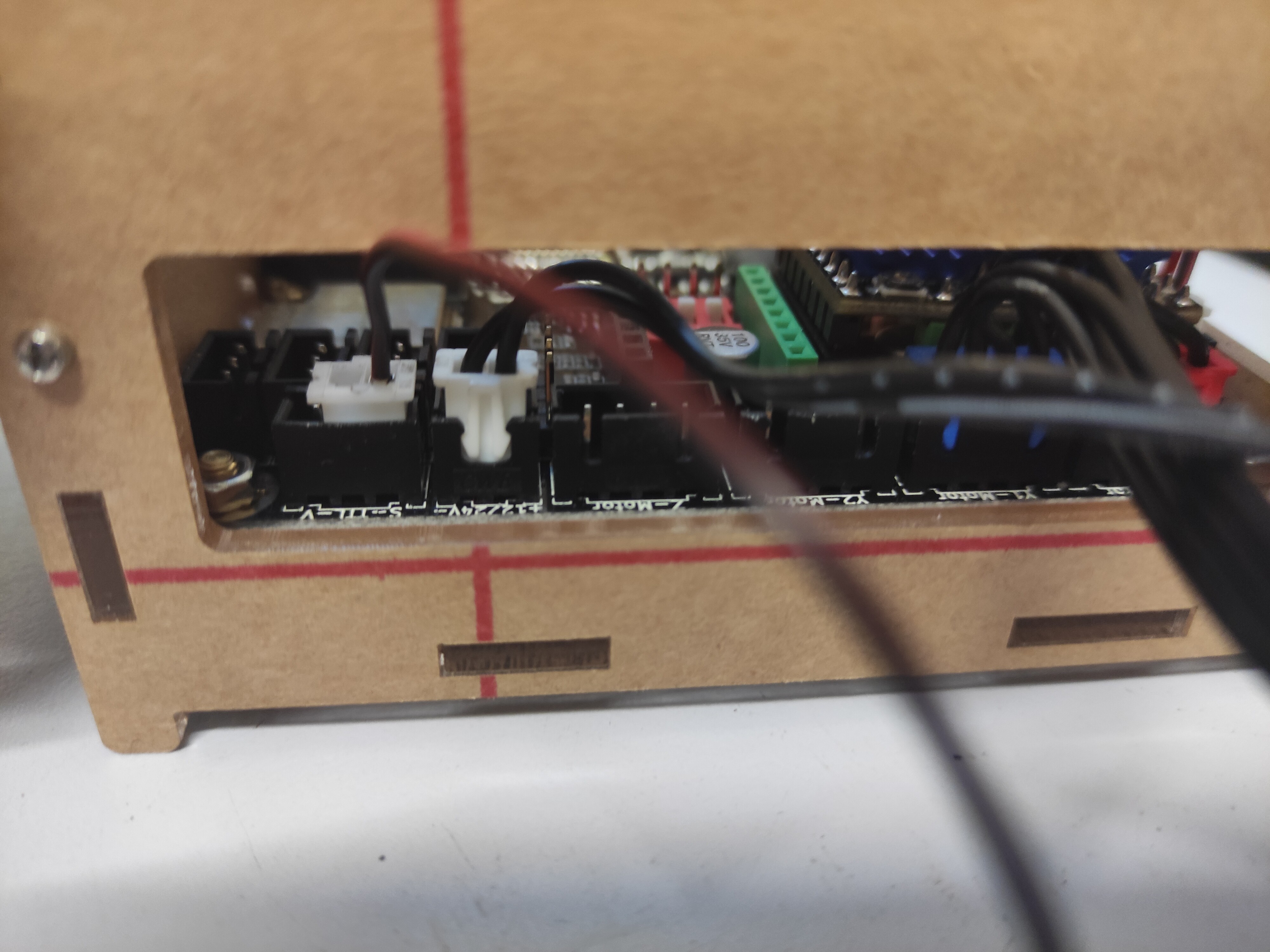
Hello, I have an Atomstack A5 (with a retrofitted M50). I ordered with a painter base MKS DLC 32 board. The X axis runs, the Y axis runs and the display runs. Only the module itself does not work. I don’t know how to wire it. On the old mainboard, the interfaces were called Laser and GS. Neither is available here. Attached are photos of new and old wiring.
thanks in advance
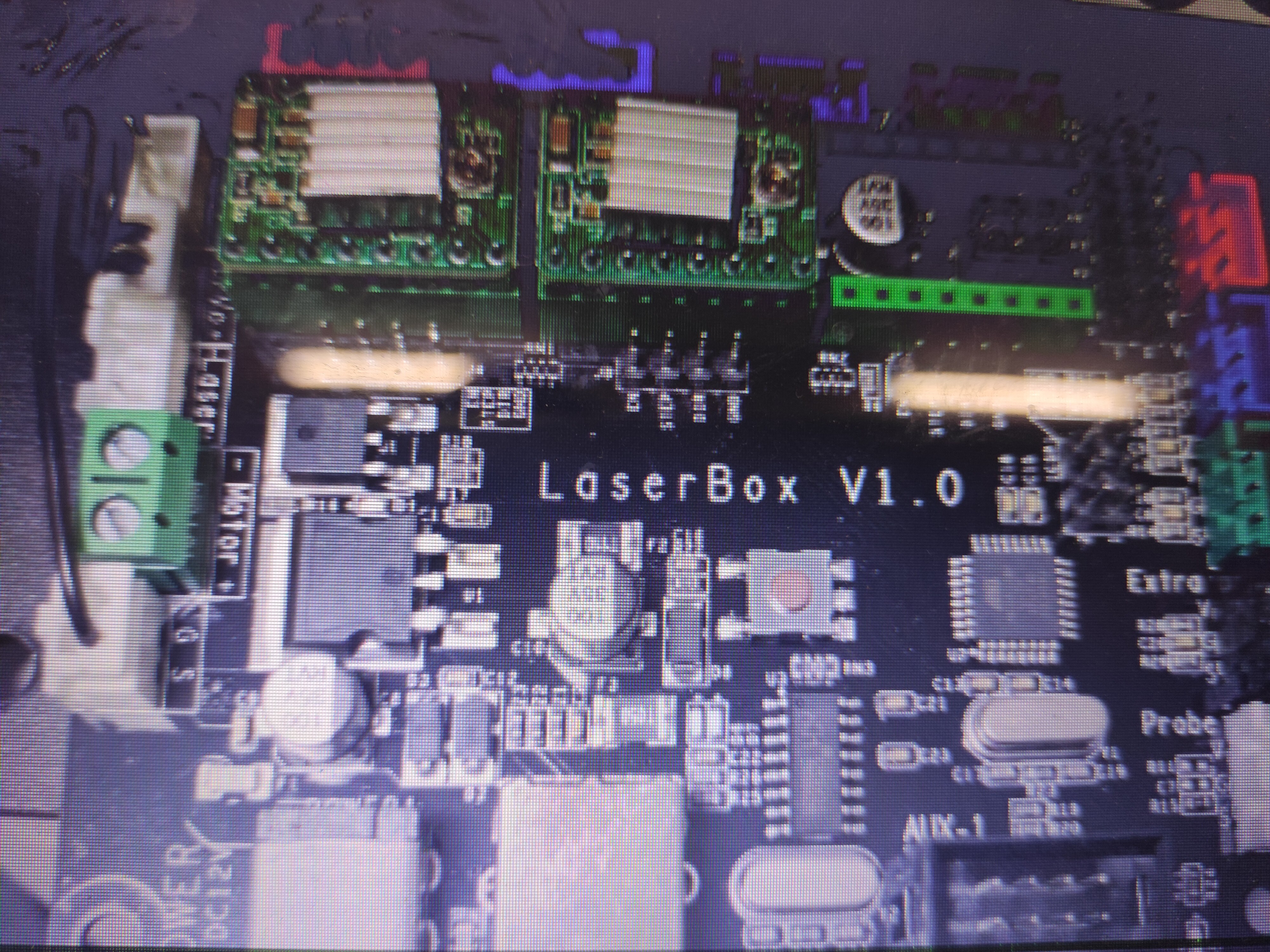
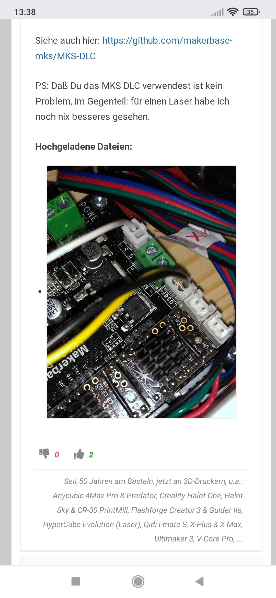
The “G” and “S” are “Ground” and “Signal” respectively. In the old picture, it doesn’t look like you are connected to the connector marked “Laser” at all; is that correct?
@mcdanlj
The Fan works If i Put in the Two black wires. The read Wire which was in the G S in the old Board doesn’t so anything. How should I Wire it? (THE WIRE WAS ON THE S, NOT ON THE G)
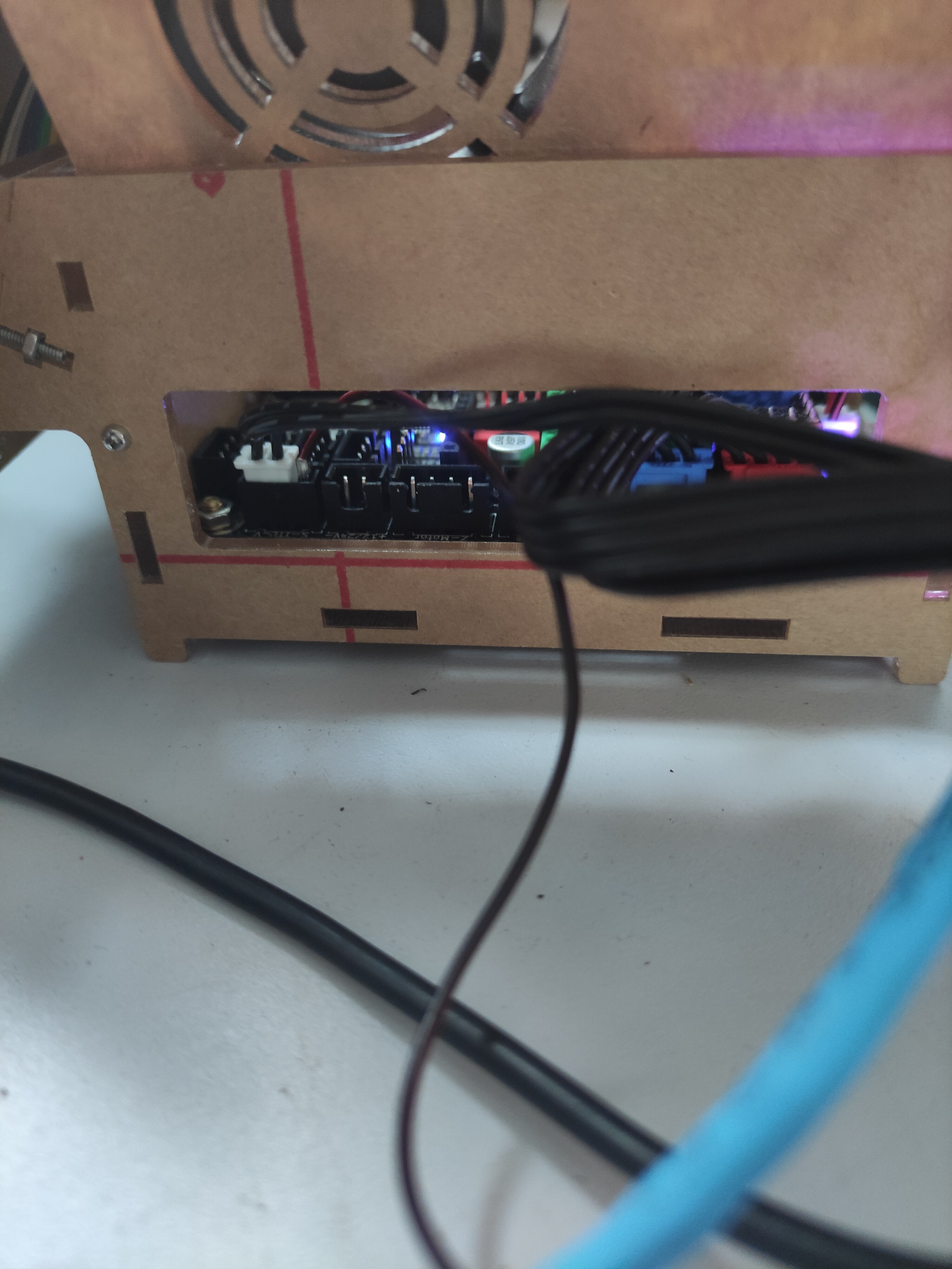
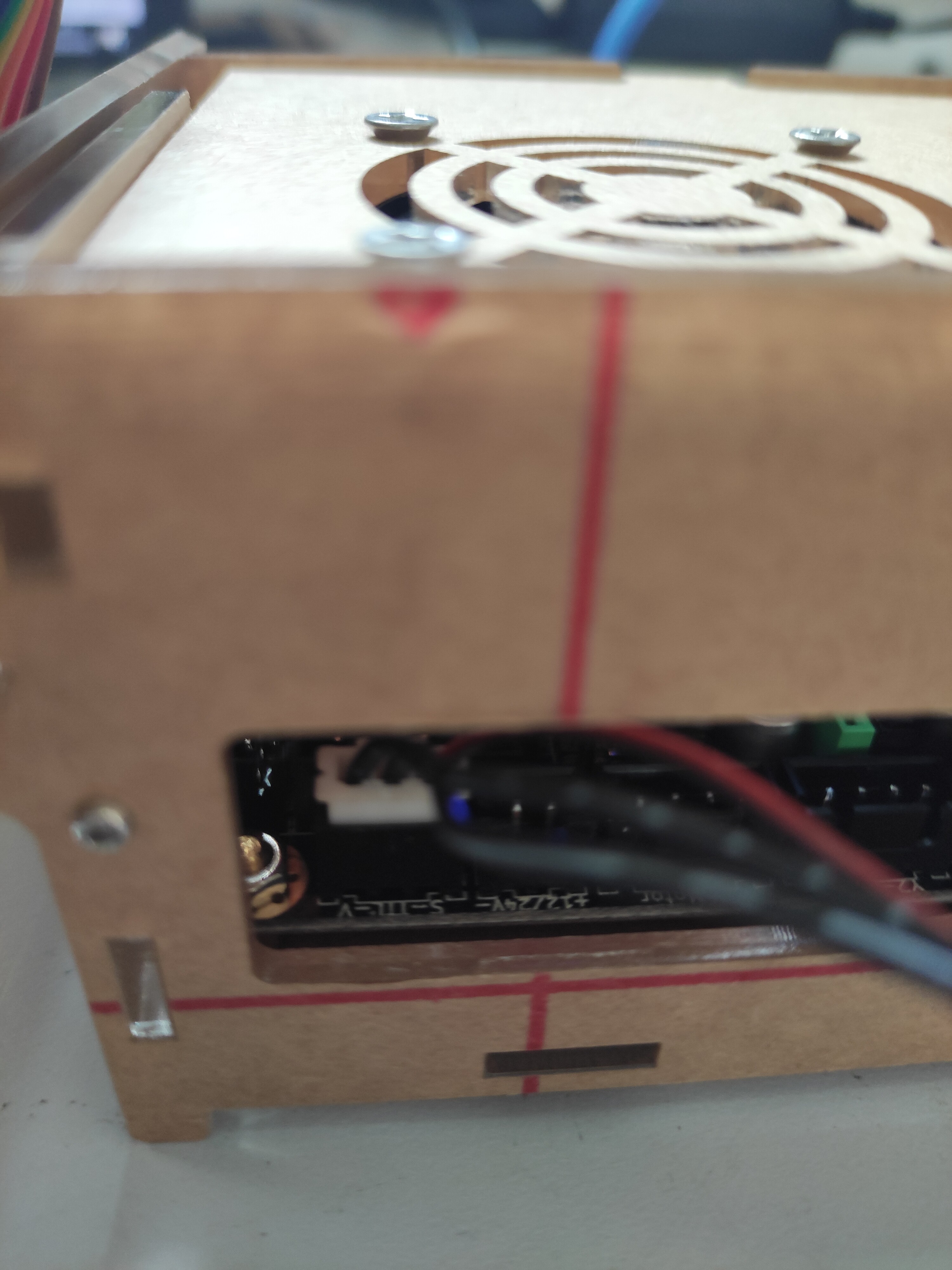
I don’t have any of this hardware. It’s very hard to read the pictures you have uploaded. They do not show the labels clearly. I’ve tried to find information by looking on the web to help you, but I’ve done as much as I can here. You will need to look at the labels on the laser to figure things out, based on the documentation that I provided above.
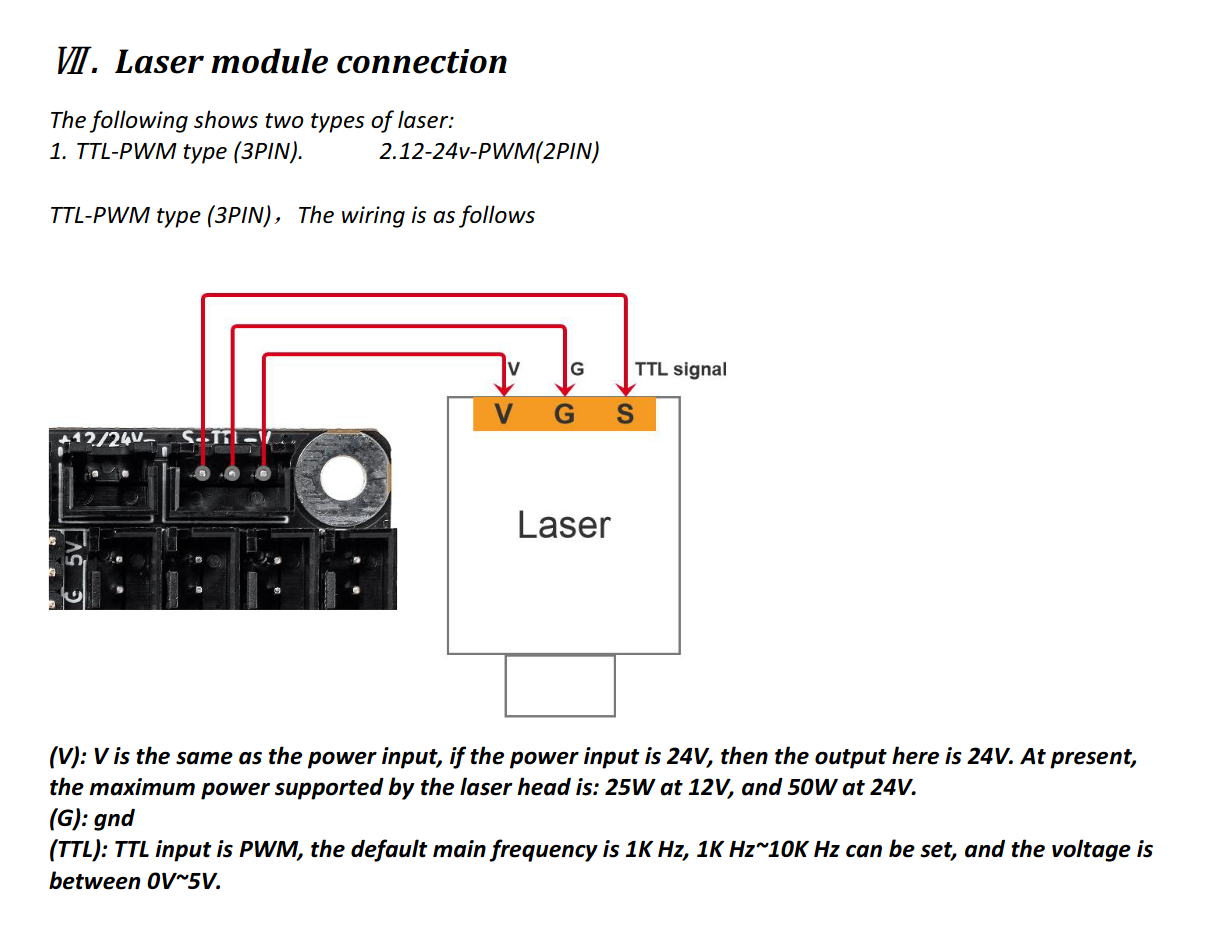
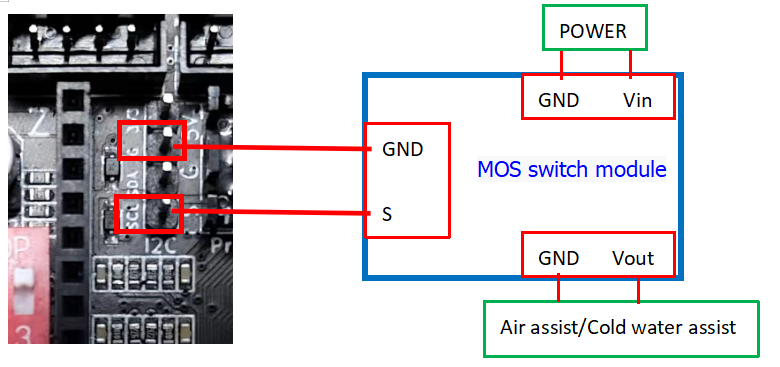
G = Ground
S = Signal (this tells the laser to turn on and off)
V = Volts (this supplies power)
You may have different labels on the laser. You are going to have to trace individual wires the way they were on the old board and make sure that you are hooking them up equivalently on the new board. I’m trying to give you information that can help you do that, but I can’t solve it for you.
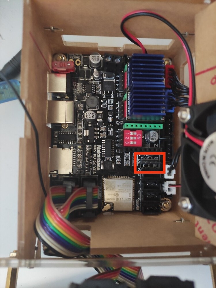
That’s an I2C header for communications with other devices. But in the MKS firmware, the SCL pin is currently configured for a coolant or air-assist relay output using M7 commands.