When you say try connecting L to ground. Does any GND work? Or does it have to be a specific PIN.
I have tried what you tell me and if I bridge L with ground the laser does not fire. I also have bridged G and P. I understand that the problem is the power supply, is that correct?
If you push the test (red) button on your LPS does it fire?
On the LPS is the LED next to the test switch ON or OFF?
The red test button bypasses all the controls and interlocks except the IN control.
Connect the IN pin to a 5V pin and then briefly push the red test button again.
Caution this sets the laser power at max.
Did it fire now?
Are you sure the supply has AC power?
Is the LED on the LPS on or off?
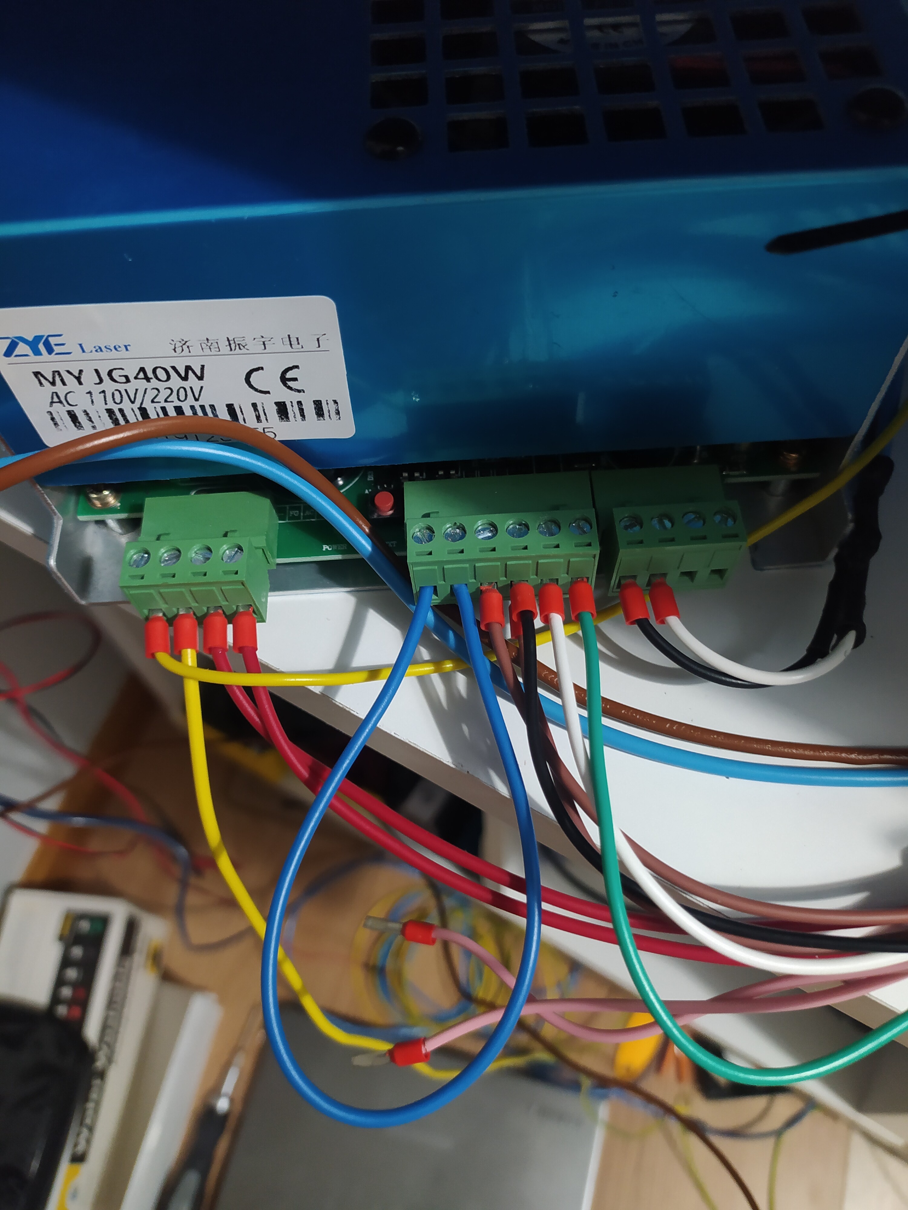
In the picture, it looks like the LPS is on a bench?
How is it connected to the laser and how is the cathode of the laser grounded?
Perhaps a picture of the whole setup will help.
Currently I have the LPS out since I have enlarged the laser and made a 3D printed box for it. I have changed the electronics for an MKS and the laser cathode comes out from the L- pin to the ammeter and from the ammeter to the laser and the positive comes out directly from the LPS.
The power supply led turns on and the fan also turns on.
In IN I have 5V which is provided by the original potentiometer.
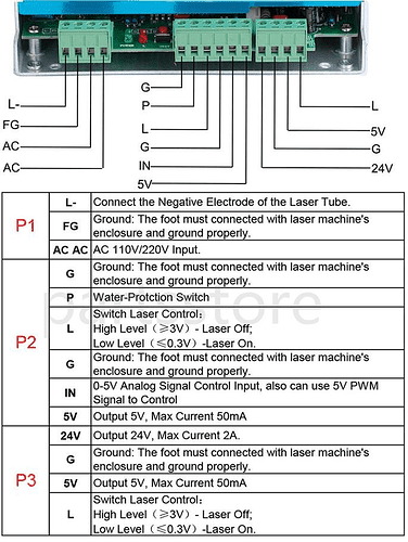
I have nothing connected to pin L of connector P3.
Do I have to make a jumper from the L pin of the P2 connector?
The FG pin must be in contact with the metal case of the laser?
Ok this generally means you have AC and low voltage.
Did you measure 5V on IN?
So with IN at 5VDC the test button does not fire the laser, right?
The test button bypasses all the controls but IN. So if the laser does not fire with the Test button and IN is at 5VDC then L is academic. The test button does the same as L but it does it internally.
Your laser has a metal case???
In any case FG should be connected to the frame and would not cause this problem.
Tell me about the machine and LPS history:
- How old?
- How hard has it been run?
- Has the tube overheated?
- How old is the LPS?
- What kind of coolant are you using?
- Have you seen/heard any arcs, hissing or crackling.
In case you are not aware the output of the LPS is LETHAL so stay far away.
The challenge is that this problem can be a bad LPS or a bad tube or both and there really is not a safe way to tell which. Therefore we check everything around it to verify it is working.
Generally if the tube is bad and the LPS is good you will get arching.
My guess is that your LPS is bad but I will wait for the answers to the above…
1 Like
Hello. I have already taken time to change tube, power supply and potentiometer.
Now I have a doubt. If I don’t put voltage on the IN input, when I press the laser test button it should shoot me?
I’m really sorry to be so heavy but I’m already desperate with the laser.
Thank you
Are you talking about the LPS button which is labeled “test” or are you talking about a front panel button labelled “Test”?
I am talking about a front panel button. Thanks
Don answered that in his long point by point reply… you need the IN control set to some voltage and it’s expected to be set with a POT connected across 5V and ground with the wiper connected to IN. Or you can hardware IN to 5V and blast the laser at 100% power.
Tell me about the machine and LPS history:
- How old?
I have changed the tube and the power supply for new 40w. Age of 1 month.
- Has the tube overheated?
No
- How old is the LPS?
I have changed the tube and the power supply for new 40w. Age of 1 month.
- What kind of coolant are you using?
CW-3000
Now I have the following setup:
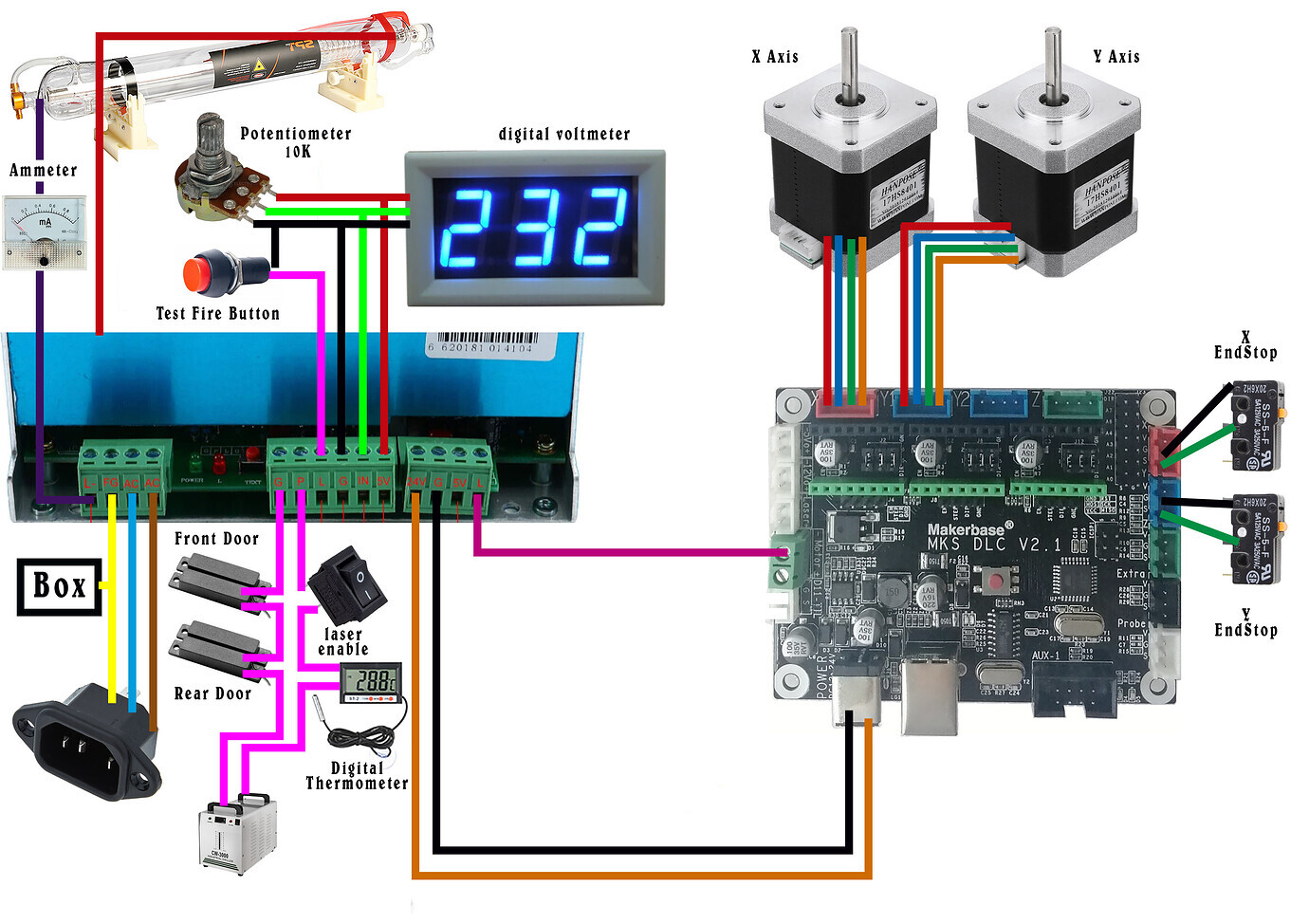
But I have realized that even if the potentiometer is at 0, if I press the test button on the front of the laser, it shoots me with a power of about 10 mA.
Also if I disconnect the potentiometer (0V in IN) and give the test button on the laser frontsl, it also shoots me at a power of 10mA.
I suppose this should not be so. Right? Is it possible that the power supply has arrived damaged?
Use a CW-3000 “water chiller.” There are lots of these on ebay for US$150 and up, marketed for cooling lasers. The problem is that they are not chillers. They are radiators that blow room temperature air over your cooling water. If your water is cooler than room temperature they will actual heat your cooling water.
FYI, that is not coolant( water, antifreeze, alcohol, etc ). And also the CW-3000 is only a room temperature heat remover and since you need to keep your “coolant” below 25C(77DegF) than your room MUST be at some temperature below 25C for there to be any heat removal from your laser cooling fluid. The CW-3000 is not an active cooler, just uses room air blowing over fins.
Note: 25C is the temperature at which you should shut down your laser. You want to operate your laser at close to 20C.
Pulling the L input to 0V while the IN input is also at 0V should not fire the laser.
Did you measure with a DMM the voltage between Ground and IN to verify it was 0V?
BTW, there is a link at the top righthand side of this page called K40 Intro and you should read every section in it. You would have known about cooling and many other aspects of the K40 from safety, setup, normal operation and customizations. Since the K40 is not a consumer product it can not be stressed enough that this document should be read from front to back before operating the machine.
New to K40: Start Here
Thanks for your information. I know the CW-3000 is not a cooler.
I have the laser in a ventilated and air-conditioned room at about 18/20 degrees centigrade.
In the future I intend to change to CW-5000
In L and G I have the test button and in G and IN I have 0V measured with a multimeter.
As I said, being IN at 0V, when I press the test button (L and G) it shoots me at about 10 mA.
1 Like
With L at 0V and IN at 5V you should get maximum power out from your LPS. With IN at 0V I don’t believe it should be firing like that.
What is the voltage on IN while you pull L to ground(press the panel Test Button)? A better way to do this would be to put a jumper between Ground and IN to make sure it is pulled to 0V.
I just did the G and IN bridging test and so effectively the laser does not activate when I press the test button.
What I don’t understand is that if I leave IN without connecting anything, the laser is activated with the test button.
I don’t recall if there is a pull down resistor on that control line but if you are skilled in reading schematics and understand electronic control logic the schematic of that area is posted on the forum somewhere and probably on Don’s blog too. Think of it this way, it is one of two laser control signals so you need to purposefully control each pin. A POT connected as in the drawing you posted should provide that level of control. ie when it reads 0V it also means the IN pin is connected to the Ground pin by the POT.