I started over with the design completely from scratch, leaving only the parameters in the file, and figured out how to start with flat pieces and create an assembly. I decided on L-shaped tenons from the same plywood as everything else; I can add hidden shims if they come loose. I’ll have to dogbone or file the radius out of the mortises for the tenons.
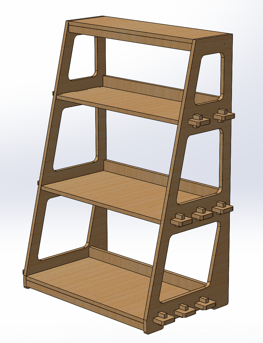
The small horizontal members will be glued and screwed to the shelves, which will be the only exception to knock-down joinery in the project. Like the tabs, they will be intentionally displayed features; I’m planning on stainless steel.
I still have to put the screw holes into the models for the shelves, but holes and countersink chamfers for the screws is I think all that’s left before I do CAM.
I’ve changed my mind: I’m 90% sure I want to use biscuit joints for attaching the supports to the shelves. This leaves only four screws to hold blind blocks, on the top inside of each side (not visible in this projection), on which the top shelf rests.
I also decided to try an experiment in which the tenons have no draw in their holding part. The tenons are three thicknesses tall, and the part that ends up sticking below the shelf will have a shallow draw to aid in assembly, but the part that is interfacing in use will have zero draw. If it needs to be tighter, I can put shims on the back side, against the surface of the side, pushing it slightly out. I am cutting the mortises with an extra 4mm intended to be inside the side slots, but giving a little room for shimming out if necessary, and I hope avoiding the need to dogbone or clean up at least half of the mortise inside corners.
I know there’s a chance this will end up wiggling, and if I have to I’ll just make new tenons and chisel out the mortices to add some draw. But I’m hoping that the tight fit makes it not matter. I have an easy way to fix it if I’m wrong, so not much harm in trying the experiment.
