Making custom length timing belt loops

When you need a closed loop belt of a length that you can’t buy, there have been several techniques recommended, including diagonal cuts with pins through teeth, and cutting through the middle of two teeth and sewing them together. However, the strength of the belt is in the fiberglass or steel cords running longitudinally, not in the teeth. These common methods do not make a strong loop.

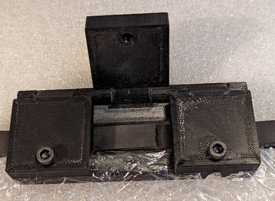
I have created a 3d-printable jig tool that allows you to make a well-aligned splice in many timing belts that preserves at least much of the strength. It is unlikely to be as precise as a commercially-prepared closed loop, but may be good enough for many uses. As long as the teeth are as wide or wider than the gaps between teeth in the belt profile, the spacing should be consistent.

It is possible to use this process without a jig, but alignment is harder to get perfect. My first attempt did not use a jig. I just held two pieces of belt together, and it was therefore out of alignment by about 0.5mm which annoyed me even though it ran through pulleys just fine. This is why I designed the jig.

Please feel free to comment with questions or to ask for help parameterizing to make a model of the jig for another kind of timing belt. All you need is a set of calipers to measure the belt, and I’m happy to help make variants of this design for additional types of belt.

Ingredients

  • More belt than you need for the loop
  • Some sort ot flexible adhesive:
  • A piece of cling wrap
  • This jig, parameterized and printed for the belt you are joining
  • Two or three machine screws (the default is M5) at least 20mm long
  • Two or three hex nuts in the same size (the default is 8mm hex nuts for M5)
  • A pin as the hinge pin for the jig

Examples

  • BeltSplicer2GT-6 is for 2GT/GT2 6mm belt, the type typically used for 3D printers, and using a strand of 1.75mm printer filament as a hinge pin.
  • BeltSplicer is for HTD 5M belt 15mm wide using a ¼" hinge pin.
  • If you need help parameterizing for another belt size, ask here!

Steps

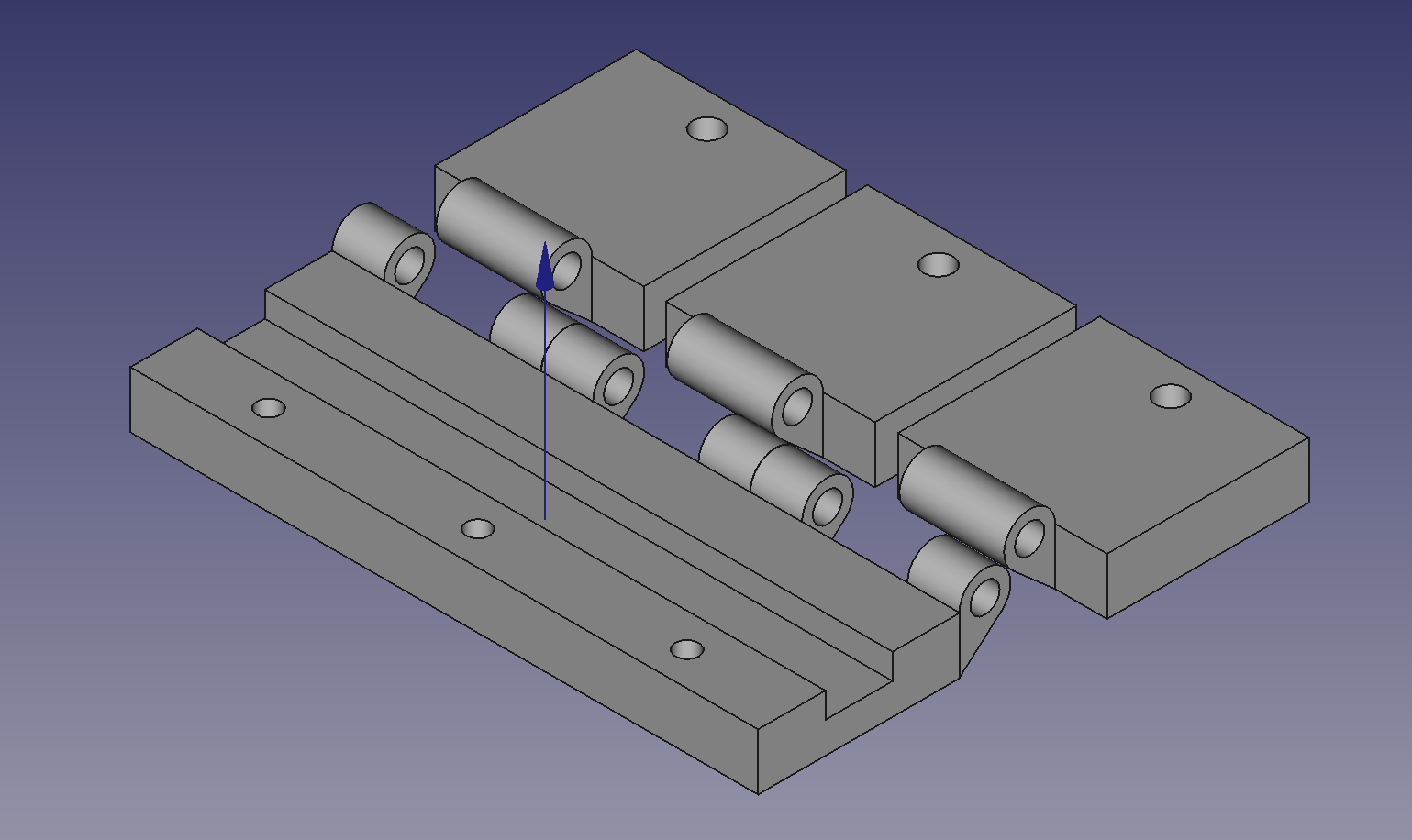
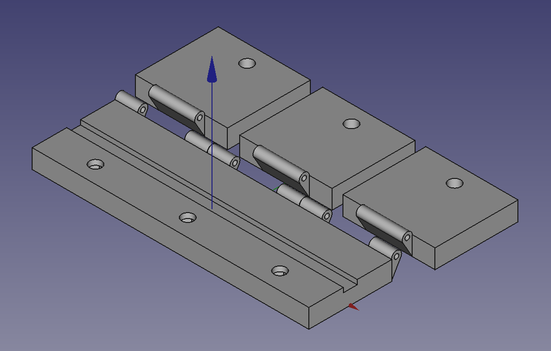
  1. Parameterize the FreeCAD model or choose the model for your belt, hinge pin, screws, and nuts. Pay particular attention to:

    1. Width of the belt
    2. Pitch of the teeth
    3. Number of teeth to overlap (I suggest 15cm worth of teeth or more)
    4. Extra teeth visible in the center of the jig when the two side blocks are clamped in place.
    5. Sizes of holes for clearance and size of nut if you substitute something else for M5.
  2. Print the jig. The type of plastic won’t matter unless you glue the bottom belt in place, in which case you want a plastic that the glue will stick to.

  3. Prepare the jig for use:

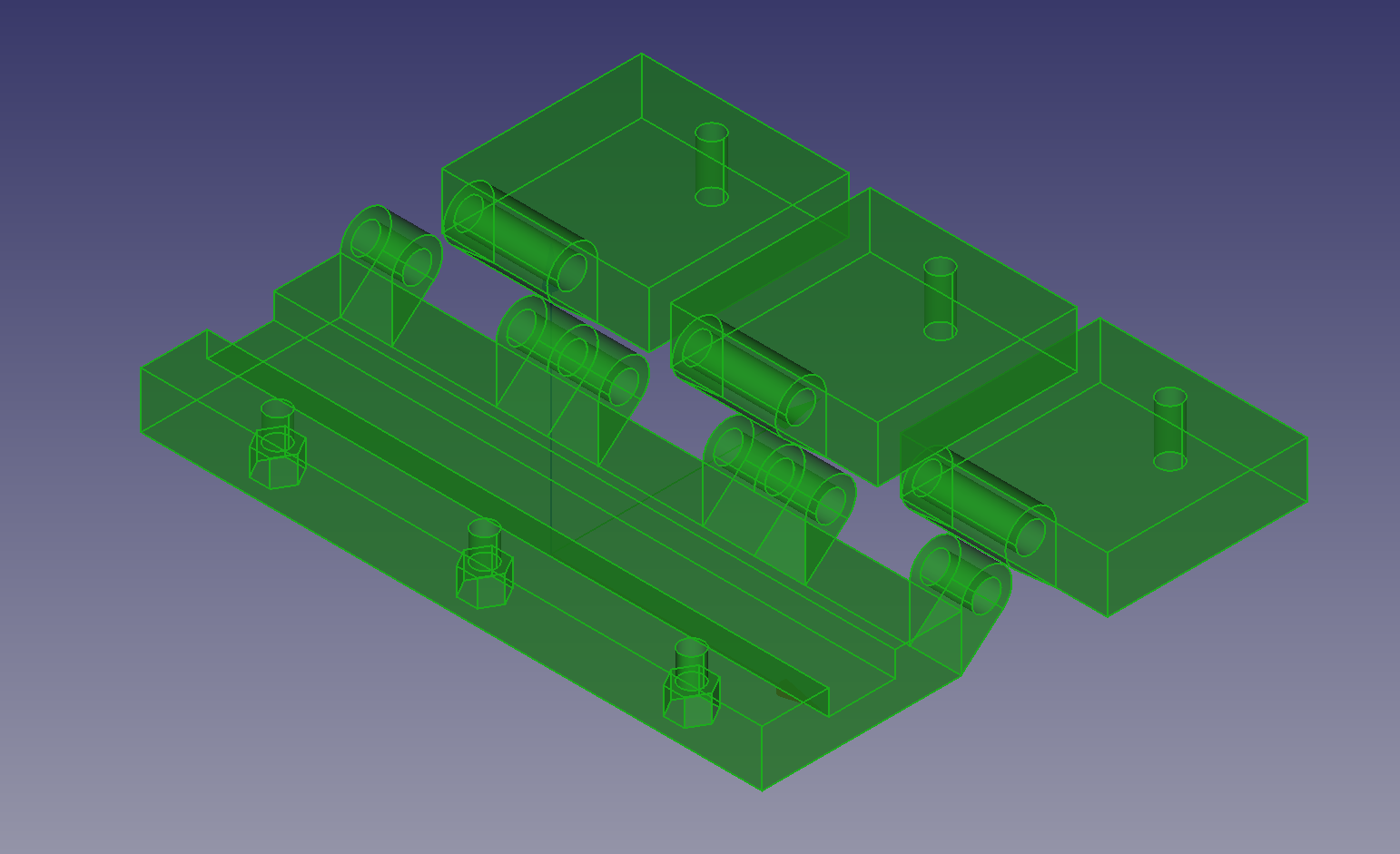
    1. Use a screw to pull a nut into each nut socket on the bottom of the main block.
    2. Use the hinge pin to connect the three smaller blocks to the larger block so that they can rotate over the top. Make sure they rotate smoothly. Sand the edges of the hinges if necessary to enable smooth movement.
  4. Arrange for a piece of belt to align the cut teeth in the jig. Choose one of:

    1. Cut a sacrificial piece of belt as long as the groove in the jig to glue into the groove
    2. Use another piece temporarily, not glued
    3. If you aren’t making the loop in situ, you may use the opposite side of the same belt
  5. Cut the desired length of belt for the loop, plus the chosen number of teeth of overlap.

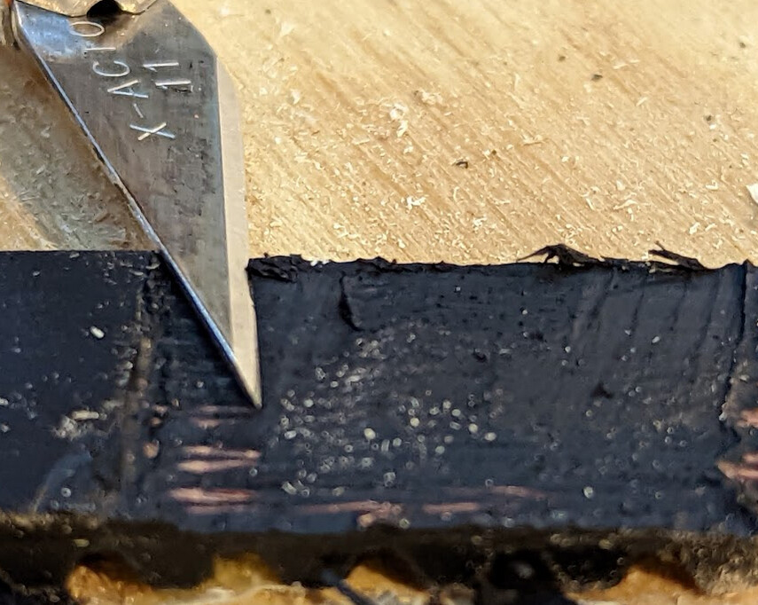
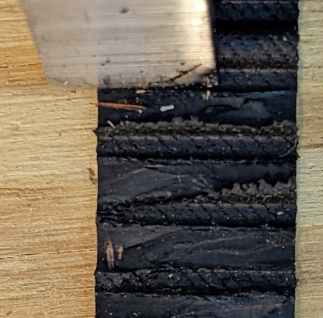
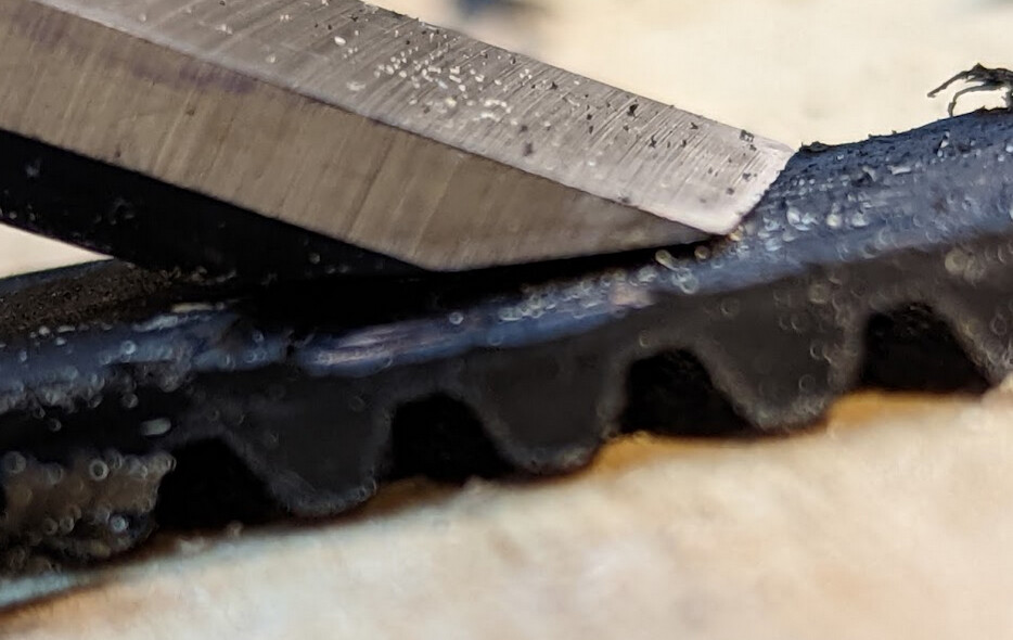
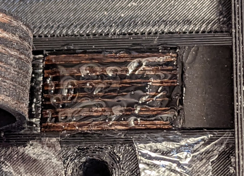
  6. At end A, use a fresh blade (the typical x-acto #11 is a good choice) to cut away the designated number of teeth. Start by cutting off most of the tooth, then carefully slice off layers of neoprene until you feel and hear the blade touch the cord. You should see the cord on the cut surface. You may find that a chisel is useful.

  7. At end B, mark the back side of the belt to the same length as the teeth you have removed from end A. This should start opposite the gap between two teeth. Cut away the back of the belt to, but not through, the cord.

  8. Test fit the ends together, with the cut faces touching each other, and with the teeth interlocked with another section of the belt (or the sacrificial piece), preferably in the jig. If they don’t fit well, you may have to trim the back of end B slightly further until they fit well. Your goal is a tight fit at both cut ends.

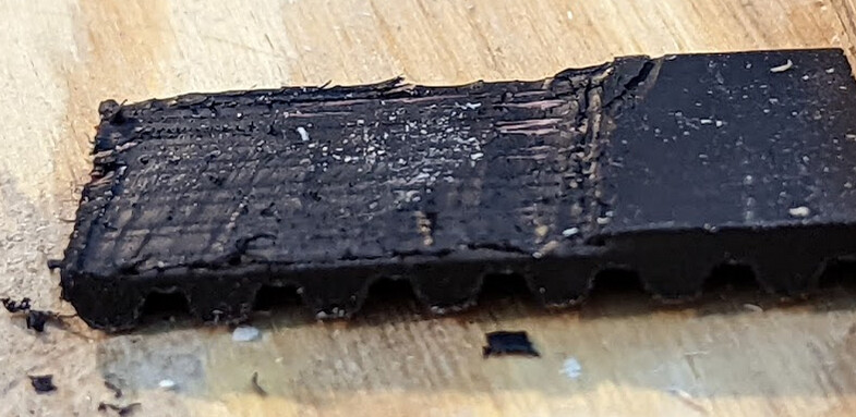
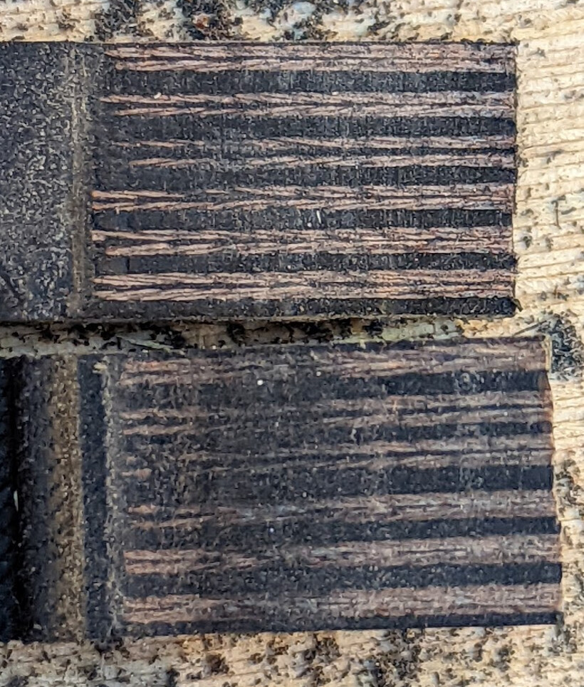
  9. Use a coarse sandpaper (60-80 grit or so) block on the cut surfaces until the belts show clearly.

  10. Trim the ends (again), if necessary, to ensure a precise fit, without leaving substantial gaps.

  11. Place the alignment piece of belt in the gap in the jig, teeth up, using cling wrap to keep the glue off the alignment piece of belt.

    1. If you are using a sacrificial piece, you may glue it in place in the jig. Set one piece of cling wrap at least as wide as the jig over the alignment belt teeth in the gap, loosely.

    2. If you are using a temporary piece of belt, wrap a single layer of cling wrap around the belt.

  12. Cut holes in the cling wrap for the screws so that the cling wrap does not interfere with the screws.

    image

  13. Make sure that there are no unintended twists in the belt, and lay ends A and B on top of the cling wrap, teeth down and cut sections overlapped, with the cling wrap between the belt to be joined and the aligning section in the groove.

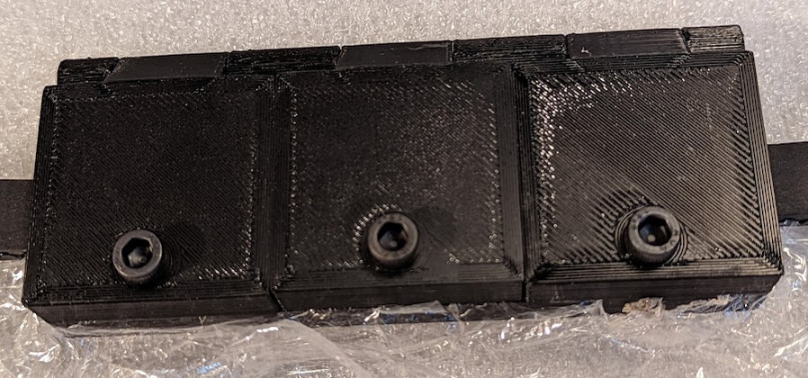
  14. Screw down the blocks at the edges to hold the belts together in place, making sure that the section to be joined in the middle is fully exposed.

    image

  15. Lift the loose end A from which the teeth were removed, and put a thin coat of adhesive on end B from which the back was removed.

  16. Lower end A carefully, making sure it is aligned, and immediately rotate the middle block to hold it in place.

    1. If using CA glue, hold firmly in place for as long as the instructions say. I recommend against using an accelerator unless the manufacturer says it will not reduce flexibility.

    2. At least if using a slower-setting glue, use a third screw to hold the middle block in place while it sets.

  17. After it is set, possibly after it has cured, remove it from the jig.

  18. Let cure fully before putting significant tension on the belt. (For example, IC-2000 reaches maximum strength in three hours)

Result

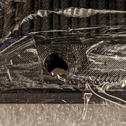
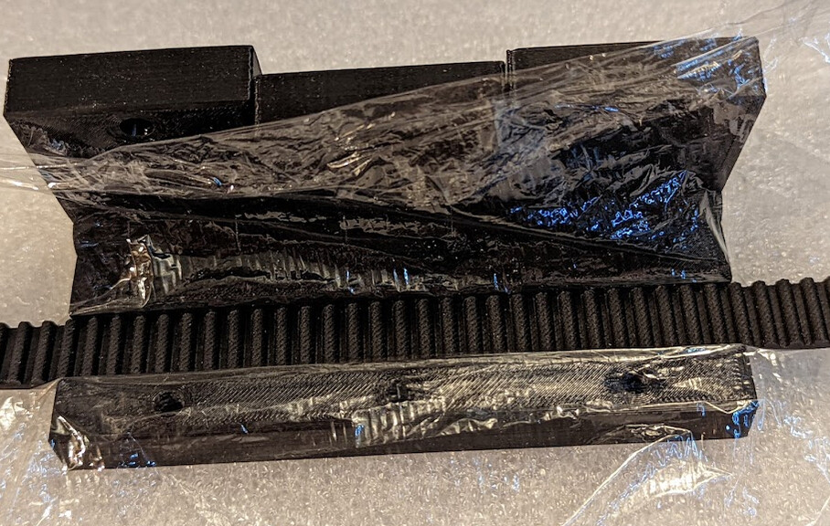
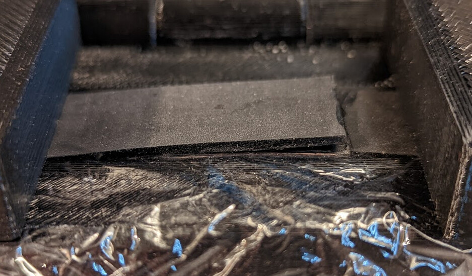
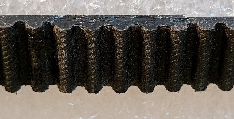
The belt will be slightly thicker (by the thickness of the cords inside the belt) than the surrounding areas, but the teeth should be well aligned in the direction of travel:

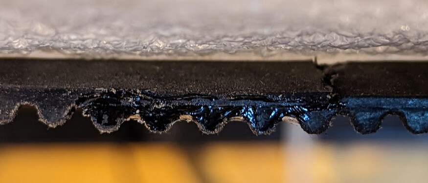
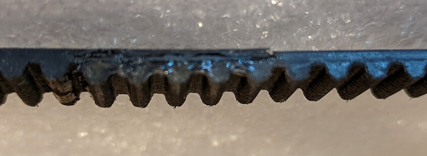
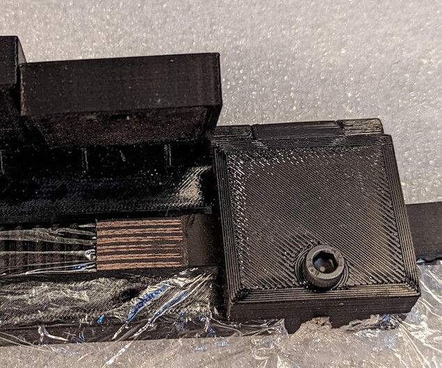
The glued section will (at least with CA glue) be stiffer than the rest, but in my experience it runs fine through even small toothed pulleys, like this:

Strength

I have tested this to failure with GT2 belt, and the join was stronger than interdigitation or clamped belt. This means that I would expect the teeth to slip in pulleys before the belt breaks.

Credit

I’m sure I got pieces of this from various places on the internet, but I can’t find this particular process. I think this is a mashup of the glue advice in back-to-back bonding ideas from Bonding GT2 belts and some pointer to IC-2000 I found somewhere, combined with the now-anonymous (deleted account) PSA: how to splice belts for custom length closed loops that used hot glue.

3 Likes

That is a cool idea! I’ll keep that in mind. I have a lot of troubles finding toothed belts in the right lengths because somehow I always design things with inconvenient between-centers.

3 Likes

I always use the cut-on diagonal, drill the teeth out, and use a paper clip inserted in the holes to hold them together. You use a small piece of the belt opposite the teeth you are splicing to hold it all together while working on it.

Of course you can use a better wire on larger belts.

2 Likes

I wouldn’t want to put the pinned tooth variant under nearly as much tension since it doesn’t bond to the cord. I did see that technique and rejected it for that reason.

The GT2 belt that I tried to use to drive the Z axis on my monocle build skipped once I put load on the bed, so it just wasn’t good enough. I cut the belt out, but intentionally not at the joint, so that I could see how strong the joint is. I haven’t managed to pull it apart yet using more force than is comfortable on my bare hands. So my scale would be insufficient to show how much force it takes even to pull apart the joint in the GT2 belt.

For replacing the belt with beefier teeth, I went a bit over the top and got 15mm wide HTD 5M belt instead.

Now I need to make another closed loop. The alignment wasn’t absolutely perfect on the first one even if it was good enough, so now I’ve started designing a parametric jig in FreeCAD. The idea is that you can put in parameters like belt thickness, pitch of teeth, number of teeth you want to overlap, etc., and then you can print a jig for belt splicing.

Here it is, set up for ¼" rod as a hinge, and M6 bolts to hold down the flaps that keep everything aligned while setting up.

After this works, I’ll make the whole thing public.

2 Likes

@NedMan, a friend of mine suggested using hexane to partially devulcanize the rubber to enable cross-linking, like bicycle innertube patch kits. Do you have any thoughts about this idea?

I spliced the HTD 5M belt today. It worked. Here are a few pictures showing the process.

Preparing the belt

I chose to splice a section 5 teeth long, so from one end I removed five teeth:

It turns out that the HTD 5M belt is harder to splice than the GT2 belt I spliced before.

So I brought out a very sharp chisel:

From the other end I removed the exact same amount of the back of the belt:

I was still facing this:

Here, you can see the fiberglass cords starting to show:

I alternated cutting and scraping with the chisel and using a fresh X-acto #11 blade.

Finally, i used an 80-grit sanding block to expose the cords and get a flat surface. It is these cords being glued together that will make the splice truly strong:

I trimmed the ends carefully, trying for a clean fit with no overlap but not much gap either, testing by holding them against another piece of belt to make sure they were aligned correctly.

Using the splicing tool

I laid cling wrap onto the base, then pressed a section of belt, teeth up, into it:

Then I folded the cling wrap over:

Cut holes for the bolts:

image

I put the end with the back removed, engaged with the teeth underneeth, and screwed down the block at that end to hold it in place.

image

Then I put the other end of the belt (with the teeth removed), being careful not to have any twists in the belt from end to end, into the other end, meshing with the area that was cut away on the back, and bolted its block down:

The ends are aligned but not yet glued:

Holding back the top flap with the teeth cut off, I applied the glue to the cut-away back, wetting it thoroughly but thinly:

Finally, I closed the middle block and screwed it into place, and waited several minutes. (The glue said 20 seconds, but I wanted to give it extra time.)

The join is quite even:

It is slightly thicker in this section, but not much. It runs easily through the smallest pulley in the system:

I hoped that a long section of tapped plastic would be strong enough for the bolt, but I could feel the threads giving way, so the next one of these that I make I’ll use nuts for the bolts. I’ll put space for nuts in the model before I publish it. Here the model is transparent to show where they will be installed:

The FreeCAD model is highly parameterized, and the README.md has extensive instructions for use.

There is a version for 2GT/GT2-6mm belt there now that uses filament for the hinge pin. Not sure whether that will work. I was just looking for something that most folks would have handy. Would be interested in other suggestions for hinge pins that people would be likely to have handy.

I’ve updated the OP instructions with use of this jig illustrated by many of these pictures.

5 Likes

Sorry, just now seeing this. I don’t think hexane would “devulcanize” rubber. It probably gets into the rubber and causes some swelling and would probably soften it up a bit.

@NedMan His point was that they successfully patch inner tubes with this and nothing else actually works for that purpose. He thought it had to do with breaking sulfer crosslink bonds temporarily so that they would reform and crosslink across the joint. Not sure if that’s “devulcanize” which I was making up on the spot. :smiley:

Yeah, I knew what you meant. :wink:. I can’t think of a mechanism where by hexane by itself would disrupt the chemical bonds. I think it’s more likely the hexane is infiltrating the rubber and allowing the glue to also penetrate. :thinking:. That’s just my guess. So for your purpose it could work.

2 Likes

I finally got around to testing this for strength, using a section of GT2 belt with about a 30mm overlap. I could not break it with my hands, or even standing on one end and pulling with all my strength with both hands. Then I took a joined section (cut elsewhere) and made a loop around my hydraulic press, allowing me to use the hydraulic press for tension. I tried this two ways.

First, I interdigitated about 100mm worth of belt, with six approximately evenly-spaced zip ties holding it together and tightened as tight as I could pull them, the teeth just slipped through.

This means that this is stronger than the teeth can hold against pulleys, which means that it is strong enough for any use, in practice.

Then I captured about 50mm of interdigitated belt between two metal plates and clamped them tightly. There was quite the loud bang when it finally gave way, but it gave way by the plate, and the join held.

I have not tried forming the loop directly around the hydraulic press, because what I care about is relative strength, and the zip-tied interdigitation test proves that the belt will skip teeth before the belt fails, which is all that matters.

4 Likes

That’s amazing and great job testing the joint.

3 Likes

Awesome write-up. Just commenting RE hexane and rubber, from a mold makers perspective. Nothing ground breaking, just some 2 cents in the interest of spreading knowledge, hopefully itll help someone at some point…

I used to work at a shop that made theme park animatronics, and while Ive never seen it done personally the old salts would talk about ‘the kerosene trick’ when the topic of scaling something to size came up. They would take a part, either silicone or latex (cant remember off the top of my head, its been a while, most likely latex… silicone tends to be a bit of a diva when it comes to not turning into snot during the cure stage…btw, dawn dish soap is just as good of a release as the expensive paraffin wax in hexane stuff, doesn’t bother platinum silicone one bit, and is a helluva lot safer to wash down the sink.), soak it in kerosene (white gas, Coleman’s camping fuel) and the kerosene would make the part swell. Then mold it while it was swollen for a scaled up part. Apparently it worked great for preserving detail across quite a number of iterations. The same was also possible for the other way too, ie shrinking a part down. If I recall correctly youd mix white gas into the material you were casting into the tool/mold. After it kicked and set up a bit pop it out of the mold, let it air out and it would slowly shrink as the white gas evaporated away. When it was the size you wanted or before the detail warped youd quickly mold it. The expanding method could preserve detail more times than the shrinking method, but still a neat trick!

Anyhoo, the talk of “devulcanizing” the rubber rang that bell in my head, so I thought Id throw that out in case it flipped a light for anyone else exploring the material science of rubber. Again, awesome write up and technique! Thanks for sharing :sunglasses::+1:

1 Like