It’s upright and somewhat level. I had a problem (didn’t set a clamp right?) at one corner so that corner is too high, so I’ll probably take the sander to the area around that corner until the top is a plane.
I wonder if I should fill the top partway with sand to make it stable and make the adjustment feet more effective at taking out twist? Might absorb vibration too.
I do not think that sand would be required. You will never get the level of precision out of a large OX build where a small amount of unevenness of the table would affect it.
You have a couple inches on me… My table is about 41" high, and I think 39 or 40" would be about perfect, but I don’t care enough to do the work to take off an inch.
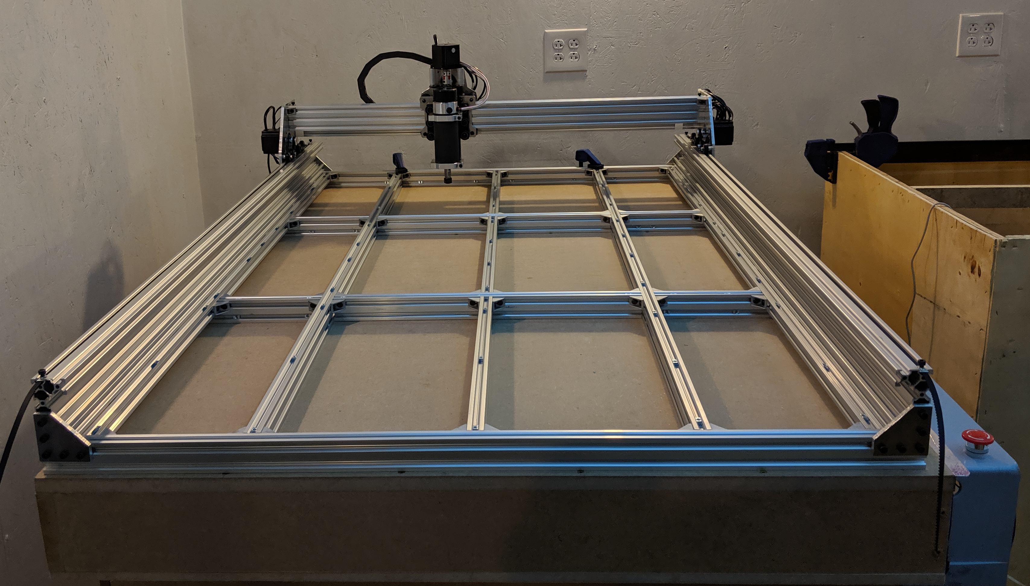
The table has some twist, I think. I mounted a dial indicator to the spindle body and moved around the MDF surface clamped down to 2040 extrusion on top of the table. The ends are 2040 that the Y c-beam is mounted on top of. The MDF is sitting on a matrix of 2040 in the middle, between those end pieces:
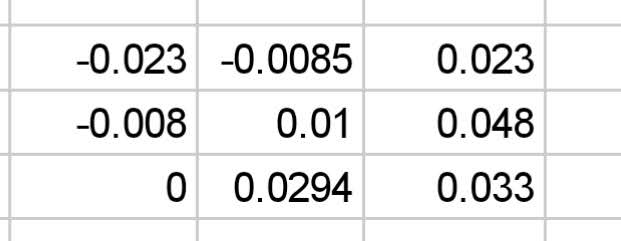
I have a total of about 0.075" (almost 2 mm) variance relative to the movement of the head:
I can’t imagine that the MDF is off by 2mm in thickness, but if the table is twisted and the 2040 end supports are twisted relative to each other, then the path that the spindle takes should likewise be similarly twisted. Perhaps not exactly aligned, but off by 2 mm seems unlikely as well. I’ll put a straightedge across the diagonal and if the top is twisted I can shim up the 2040 pieces to take out the twist, but if I twist both the MDF and the table the same way it seems like I’ll have the same problem.
If the machine is twisted, then surfaced isn’t flat. If the corners of the table aren’t co-planar, the machine will be twisted out of square, and if I surface the spoilboard, I’ll end up with a “potato chip” shape cut into the top.
With a height gauge, I discovered that the gantry beam was 0.1mm higher above the right-side Y c-beam than above the left-side Y c-beam. I loosened the right side screws a bit and gently tapped it down with a rubber mallet until I measured it repeatably within 0.02mm side to side relative to the top of the c-beam. I’ll call that good.
I put the whole frame up on pieces of c-beam above the table, and am most of the way through re-aligning all the joints vertically. I’m clamping the joints top and bottom with extra pieces of extrusion to hold them aligned, while re-fixing the corner brackets. This should reduce the variance across the top. I’ll check by running the indicator down the tops of the bare cross-pieces when I’m done.
The table does have a bit of twist, so I’ll shim that out too. Probably due to not fixing the imperfect side panels well enough. It’s not as flat as I measured earlier.
I finished squaring up Z on all the individual joints across the bed. I put the frame up on stacks of extrusion 100mm high at the corners, and then used a 1500mm 2080 extrusion and various feeler gauges to determine shims to add. Then I set it down on the shims and clamped it in place.
Running a dial indicator across rails front to back is within about 0.01" / 0.25mm. Running a dial indicator side to side on the front rail (haven’t figured out a setup yet to reach the back rail) is about 0.03" / 0.75mm side to side (was 0.04" before I loosened the left side and encouraged it upwards with a rubber mallet). The variance in thickness of the MDF is at least .15mm having measured only along one edge so far. Measuring 9 points across the MDF bed as before, my max variance is down to about .05" / 1.25mm, so I took out 1/3 of the variance by squaring and shimming.
As far as I can tell, about 3/5 of my lack of alignment is in the plates, out-of-center tapping of the gantry extrusion, or some combination of both. I think I have about .012" end to end of twist on the back rail relative to the front that I could shim out, but otherwise what I have is probably about as good as I’m going to get without at least modifying the side plates.
If I use safe Z clearance and extra cutting depth of 1.5mm I should be in good enough shape for most through-cutting jobs in the meantime. I do have one thing I want to cut that has some fairly precise depth requirements but those cuts are localized and I can just use that area of the bed to home Z on my stock and Bob’s my uncle!
Until I fix the side plates to square the gantry with the rails, though, surfacing the bed will scallop it because ultimately the head is out of tram with the bed. So I see an hour or three of disassembly, playing with needle files, and reassembly, probably repeated a few times, in my near future.
Leveling an engine lathe was so much easier because I knew everything was essentially square, and all I needed to do was adjust the feet until the ways were level and square to a test bar. With this OX, I’m having trouble with errors stacking up, so hunting the real sources of various variances isn’t as easy.
I spent some quality time with master precision level, dial indicator, dial test indicator, and various sizes of straightedge. I’m glad I’m using c-beam, because even that deflects enough under the weight of the gantry to make it tricky to use the level to take out twist front to back. I’ve discovered that the v-rail pieces aren’t really as straight as I hoped. So I’m backing off on tweaking the plates for now, until/unless I’m certain that’s what I need to do.
It would presumably work out alright to utilize 1/8" hardboard, giving it is stuck and screwed. Yet, on the off chance that it were me, I would utilize the 1/2" . My first OX was a torsionbox plan with 3/4" bureau grade pressed wood on top and 1/2" bureau grade employ on the base with every one of the ribs made of the 3/4" material. I really catapulted the Y hub rails to the side of the twist box so I didn’t require any of the cross supporting and made the rails solid as anyone might imagine.