Building a cheap laser engraver (P1)
As promised, I’ve written a summary of my experiences building a budget laser engraving machine for the benefit of members.
I decided a while back to add to my maker device collection. I already have a CR-10 3D printer and a few other toys, but I was interested in either a CNC router or a laser cutter/engraver.
I did a spot of research and found that laser cutters are basically either CO2 or Fibre and require too much space for my small workroom. I settled on a diode laser engraving machine, with the idea that I might use the knowledge gained to build a CNC router using the same or similar kit at a later date.
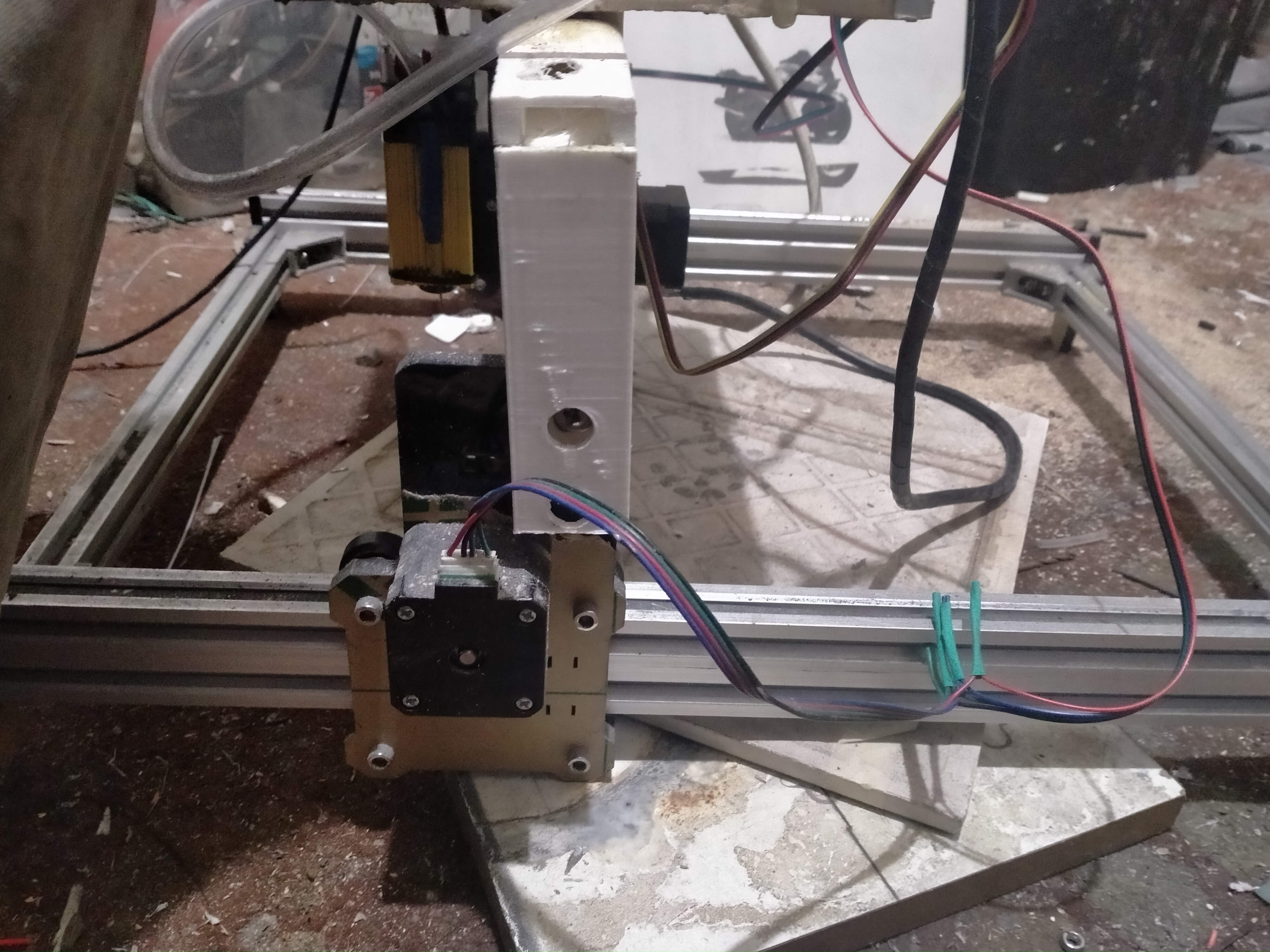
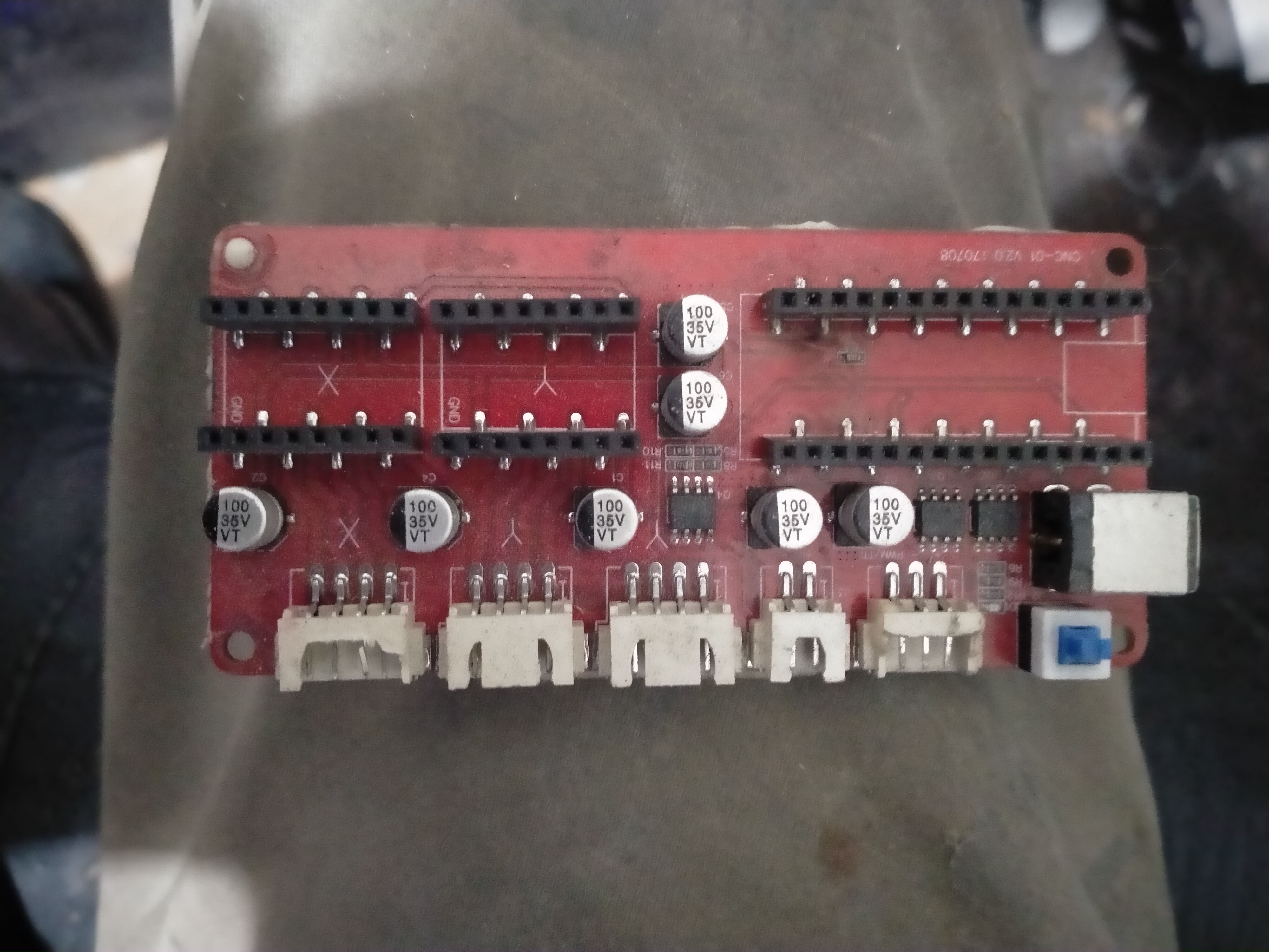
My first purchase was a frame/chassis for the engraver. I searched eBay, Amazon etc and came across something promising. Amazon had an LG-3 frame, with no laser or controller, for about £40. This was cheap enough for me to take the risk and buy it, so I did. It came from China and was here within 10 days. The instructions were pretty terrible, but assembling the unit was not a particularly difficult task and, after studying the parts for a while it was pretty obvious how to proceed. This I did and within 30mins I had the thing assembled. I couldn’t do anything with it, of course, having no end-tool. The frame looked (and looks) pretty reasonable. It is built from extruded aluminium rails – like many or most similar units. It has 3 Nema 17 steppers and a basic timing-belt drive system for the X and Y axes (two Y drives and one X drive). It also came with an unexpected bonus – a controller card, capable of driving a laser or router. The advert specifically said that no card was included, so this was unexpected bounty.

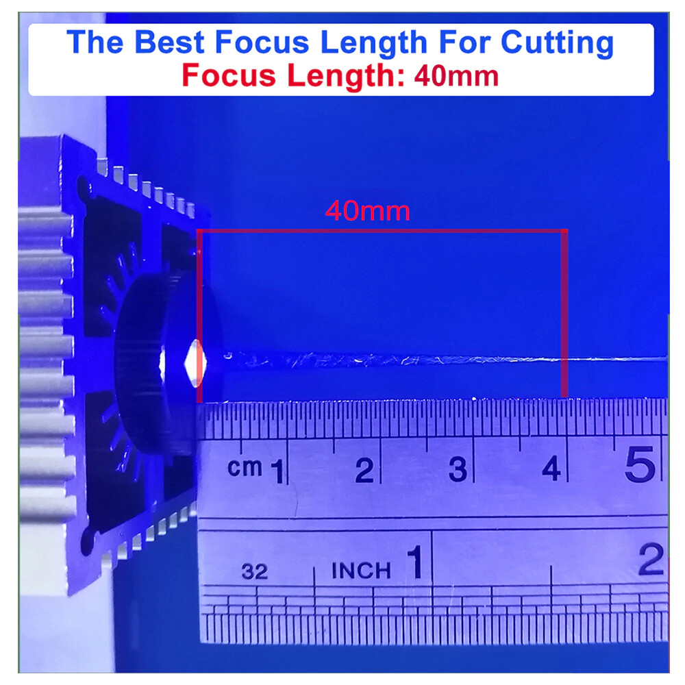
Next I needed to get a suitable diode laser head. After consulting here and checking sources, I finally decided on a ‘40W’ laser from China (via AliExpress). Members will know that the headline figure is NOT the actual laser power with diode lasers. Informed sources tell me that diodes can generate about 7-10 W max. This unit claims 10W ‘optical power’ which is probably about right. The unit arrived in 8 days, and I quickly set about installing it. This was simple – the unit came with an adjustable carrier which simply bolted to the plate on the X-axis carrier. It was then plugged into the bonus controller card, and the setup was done.

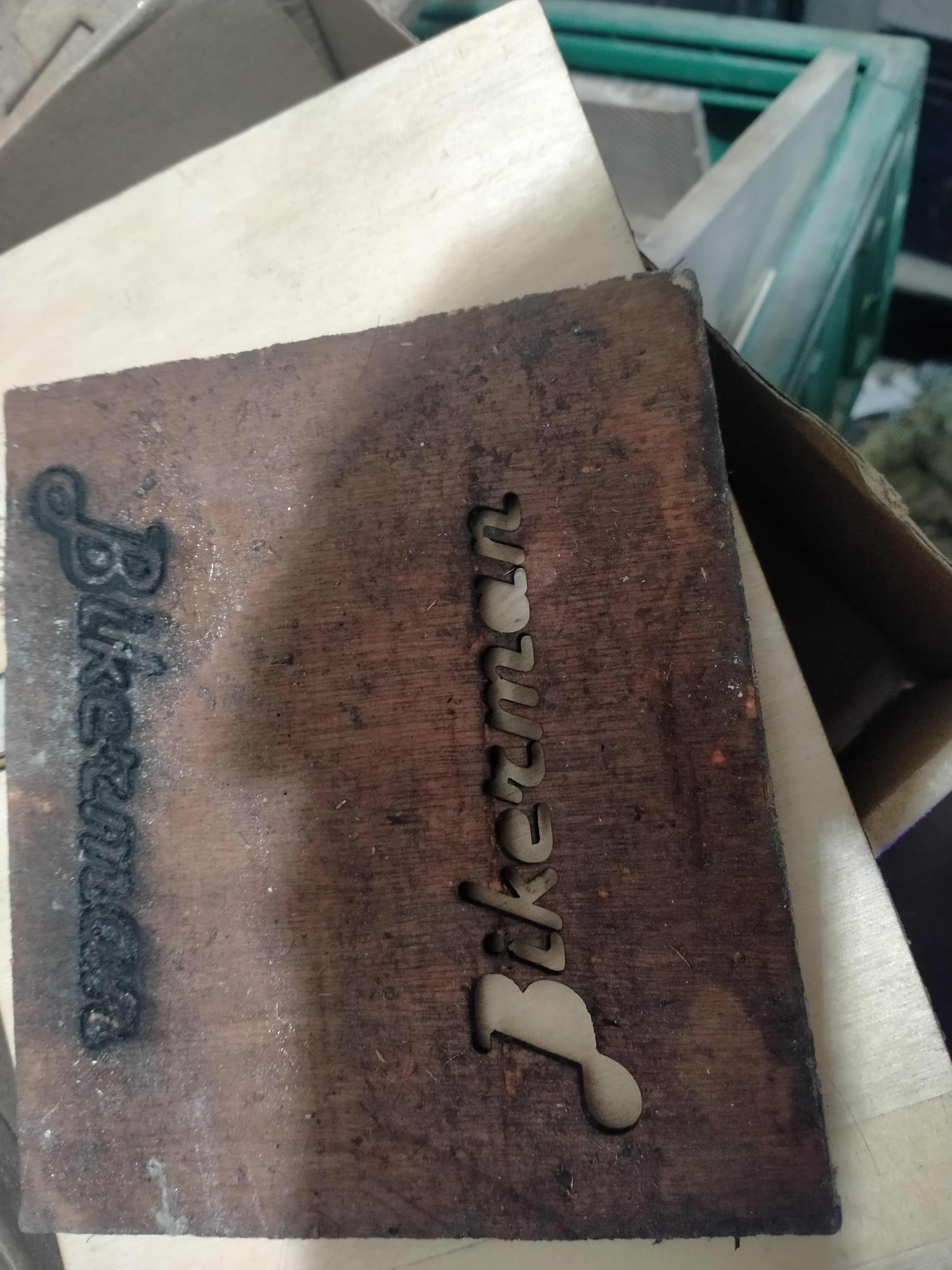
I fired up the unit, using software described in the documentation and downloaded from the manufacturer’s website (a product called VigoWorks). The unit sprang into life and behaved as I expected, apart from needing to have the direction of the Y-axis motors changed (a simple check-box in the software). The supplied card was basically an Arduino Nano with 2 A1988 stepper driver chips. I quickly loaded an image and tried to engrave it on some spare plywood I had. It worked pretty well first time. I then tried to cut the same plywood (3mm) and found that it did it with 3 passes at low speed (200mm/m).
Now that I knew it worked it was time to step back and consider the next move. It was immediately clear to me that air assist was needed, and fortunately I had a suitable pump available. I then used the needle from the syringe of a printer ink-refill kit, and a length of 8mm PVC tubing to improvise something which could be cable-tied to the laser unit.
I also needed a power supply (to this point it was simply connected my bench supply) – but here again I have a box full of PSUs from various kit, so no major problem. After more consultation on these forums, I decided not to connect the air-assist to the controller, deciding instead to have a simple toggle-switch, with the pump connected directly to the chosen 12V PSU powering the unit (I settled on a 20A 12V supply from an old desktop computer).
At this point I had my first setback – the controller card just stopped working. Fortunately, the Nano and 2 driver chips are socketed, so I quickly stuck a new Nano into the board, uploaded the firmware (using the supplied VigoWorks which makes this simple) and was back in business…. for a while.
A couple of days later the card failed again. This time there was clear scorching on the PCB and it seemed to me that one of the A1988s had received a nasty jolt in a place it didn’t want it. It could have been careless handling, bad design or an act of God…no use wasting time on autopsies. Fortunately, again I had a spare controller for my CR-10. (The original Creality card failed about a month after I got the printer – the printer would get to temperature and simply keep heating until powered off, so I got a replacement card).
Also, fortunately I had spent a spare hour examining the duff card and found that one of the big caps on the board had simply become detached on one pin. A quick dab with the iron and the card was restored to health. I therefore determined to use this to drive the engraver. This was easier than I anticipated. The procedure was basically as follows:
- Connect the card to USB and fire-up the Arduino IDE.
- Download the latest version of Marlin and compile/upload to the card. This went smoothly
- Connect the 12V and Gnd from the laser to a 2-pin fan connector on the Creality board.
- Connect the PWR lead from the laser to a leg of one of the MOSFETS on the Creality board (this info was the result of a quick web search) to supply 0-5V which controls the laser power.

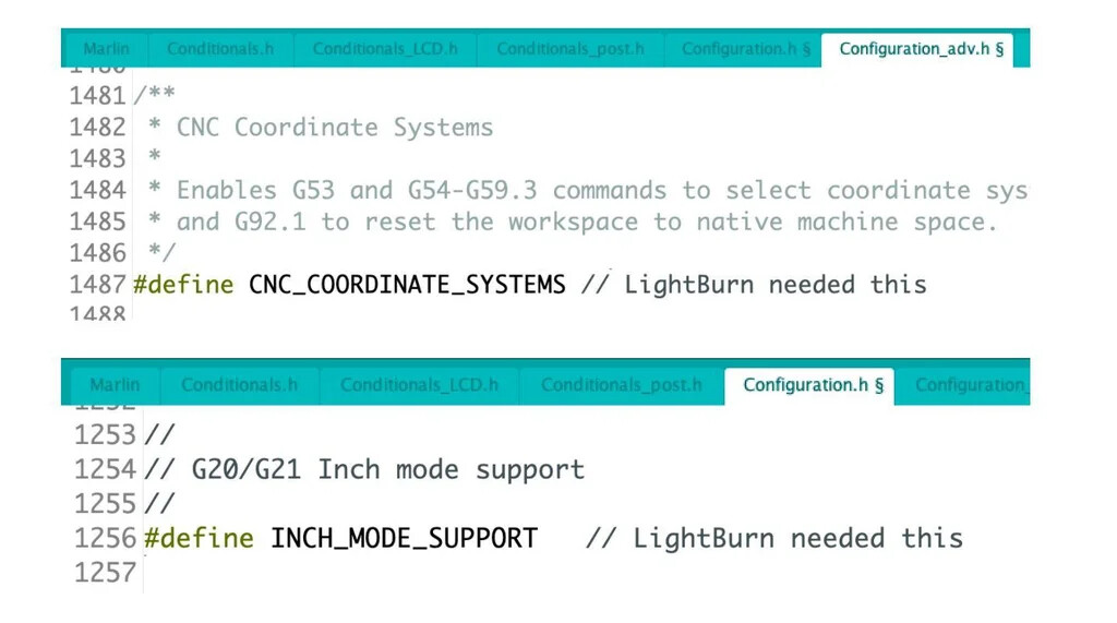
This all went without a hitch, but the card would not work with either VigoWorks or LightBurn (I downloaded the trial version and liked it). Another search of the web revealed that a couple of lined were needed in the Marlin config files. Once added, recompiled and re-uploaded the problem was solved.
I build a rough and ready box from bits of ply and put the PSU, controller card and air pump into it. I then 3D printed a plastic rail to sit above the X-axis gantry to hold the box. This was/is a temporary measure to keep things manageable. My next alteration will be a home-built acrylic box to house the engraver and provide air venting – at this point I’ll house the ancillaries in a more permanent manner.

So, I am waiting for some sheets of acrylic to arrive, at which point I will construct a box to hold the unit and figure out a way of exhausting the box through the workroom window (I have a glass hole-cutter, but I need to feel brave before trying this, so I’m just going to have a drop of 20yr old single malt before I make the attempt – purely medicinal of course  )
)
More to follow……