With the “DRV” flavor (external steppers), that pin isn’t connected:
The description for that pin:
NC:未使用,也就是不用接线的;
NC: Not used, that is, not wired;
With the “DRV” flavor (external steppers), that pin isn’t connected:
The description for that pin:
NC:未使用,也就是不用接线的;
NC: Not used, that is, not wired;
M2Nano V7 PDF:
供电要求(5V 实测<40mA,以下 100mA 是备用余量)
- 5V(4.75V - 5.25V):大于 0.10A = 100mA
- 24V(23.5V - 28.0V):最小 1.2A,最好大于 1.8A
- 5V、24V、激光电源,这三者要共地
Power supply requirements (5V measured <40mA, the following 100mA is the reserve margin)
- 5V (4.75V - 5.25V): > 0.10A = 100mA
- 24V(23.5V - 28.0V): min. 1.2A, better than 1.8A
- 5V, 24V, laser power, these three should be common ground
If I read that right, the measured consumption was less than 40 mA, but they recommend to use a PSU which is rated for at least 100 mA.
Can you post the PDF?
Those links do not resolve for me?
It’s strange that the board could draw only 100ma when the CH341 itself draws 30 ma.
Here is the link to the manual that I translated through Google.
Thanks forgot about this doc…
The host name can’t be resolved? Or do you get some error message from the server?
Pasting the link in a different browser worked just fine for me.
Try pasting it into a new incognito window.
Got the links to work, thanks.
The version of the M2 nano in these documents is different than those in K40 in that the 5V pin is NC.
Well, if the DRV version doesn’t connect that pin, it would seem to imply that the 5V there is specifically a 5V logic supply for the stepper drivers on the normal version with the steppers on it. But do I understand that it did it not buzz out to any pin on the DRV8825s on your nano?
The V7 from 2015 (first PDF) and the V9 from 2018 (shown in dougl’s pic, the one almost everyone got nowadays) look very similar at least.
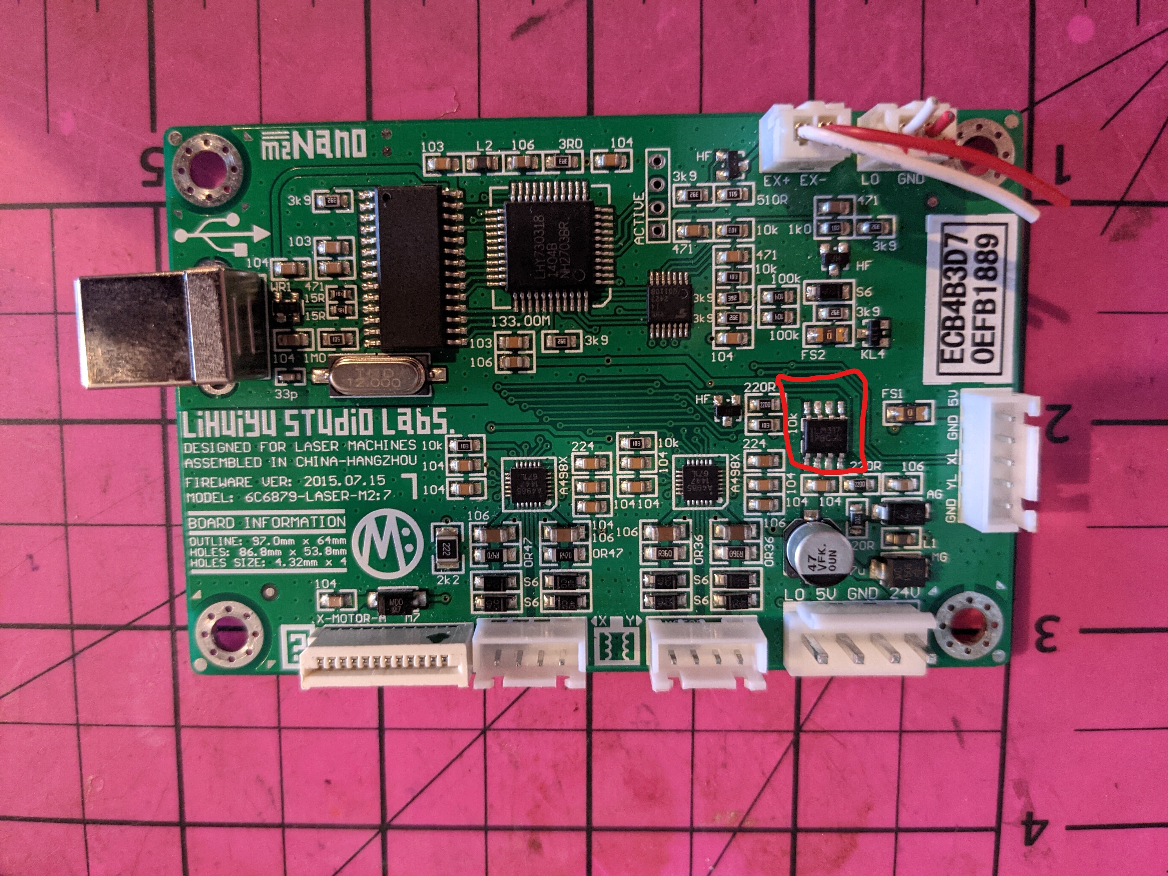
That small chip on the right of the V7 is most likely also a 78L05 voltage regulator. They are also available in this 8-pin package.
The power consumption of the V7 and the V9 are probably about the same. It doesn’t look like there were any major changes. The tweaks are likely all about saving a few cents here and there.
The CH341 should draw a lot less than 30 mA since it isn’t moving a lot of data around. According to its datasheet, 30 mA is the maximum and 12 mA is typical.
40 mA in total sounds kinda plausible. Even more so if you consider that second 5 V source via the voltage regulator. I really wonder why they did that.
Either way, 100 mA minimum for the 5 V supply seems like a sensible recommendation.
I completed some final measurements, not because I have any interest in the Nano but to better be able to help those with M2Nano problems. [I am moving on  ]
]
These questions come to mind when I see K40 host connection problems and users replace their LPS with non-stock versions. Therefore I paused my other projects to see if I could get rational answers.
My conclusions are not resolved from an exhaustive trace of the PCB but from external continuity measurements that lead to logical, but potentially misleading conclusions. I have no plans to trace these boards…
Will low capacity or no 5vdc power to the Nano cause a problem?
It depends. Some nano versions derive 5vdc internally some don’t. For the ones that don’t create it internally, an external 5V must be provided. All versions that I tested had a 5vdc pin. In one case that pin was NC and the 5vdc was created by an internal LM317.
Can the Nano’s 5v be provided by the USB host?
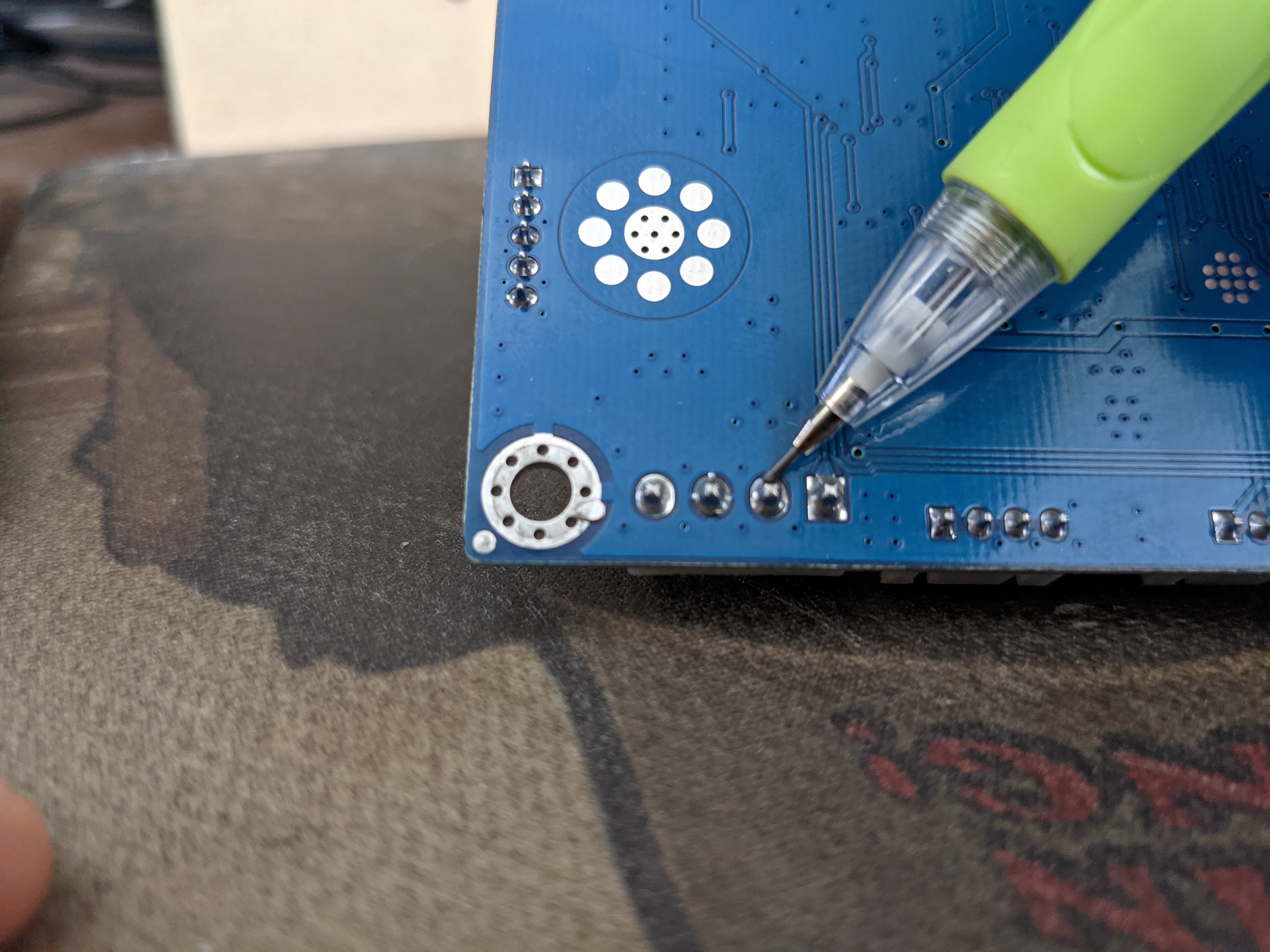
No, all versions tested show no connection between the internal 5v buss and the USB 5V.
Can the Nano run without its 5V input?
It depends. Some nano versions provide internal 5vdc some don’t.
Is the Nano ground connected to the host USB ground?
Yes.
I have three M2Nano boards and they …wait for it…
ARE ALL POWERED DIFFERENTLY  !
!
I did these checks on the three boards I have:
I tabulated these measurements below:
---- **Nano 5V power schema ----
| Model | Firmware | 341A-28 5V | 5V in | 5V endstop out | 7805 | LM317 | USB to 5V | USB to Gnd | Note |
|---|---|---|---|---|---|---|---|---|---|
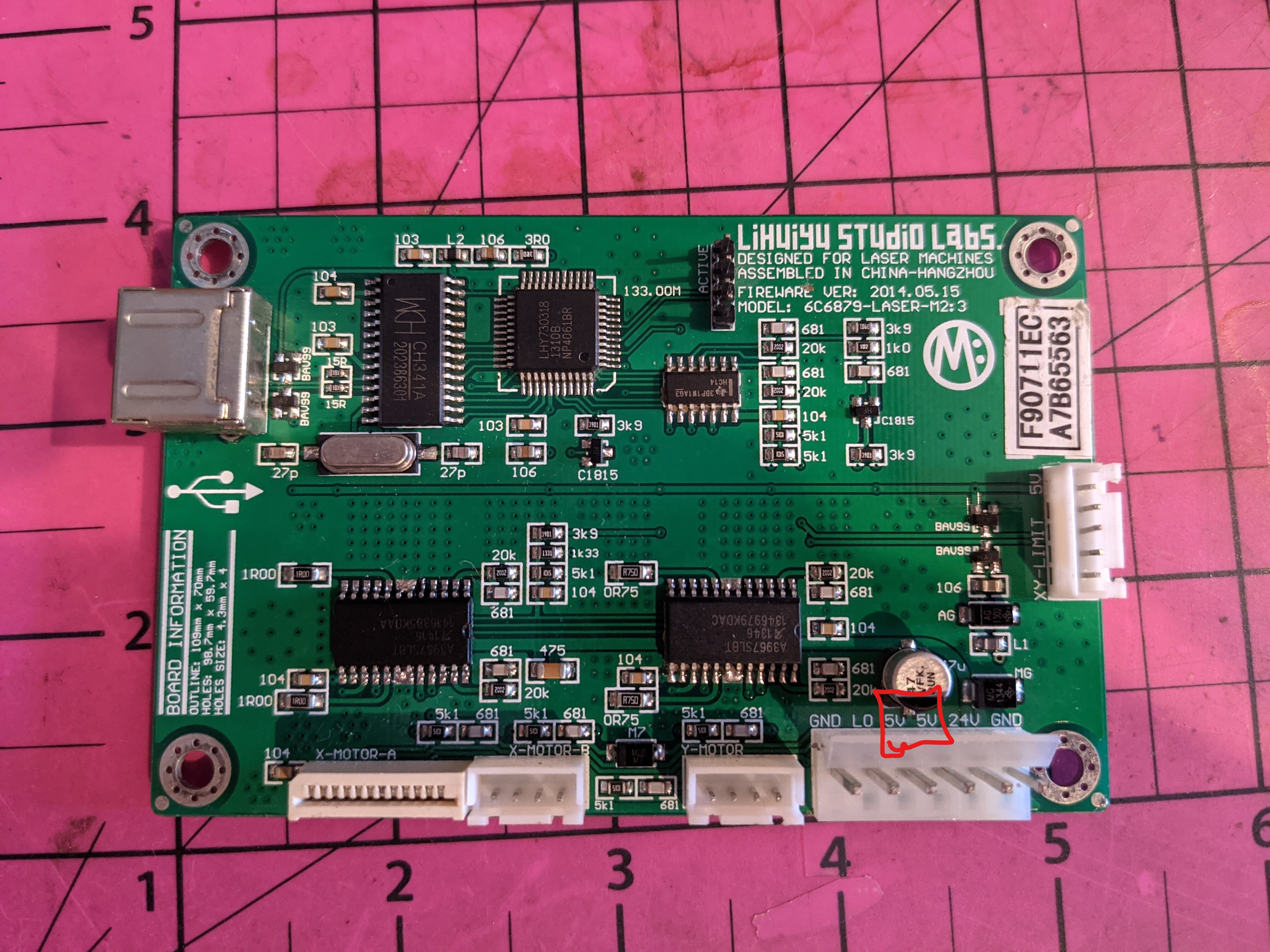
| 6C6879-Laser-M2:3 | 2014.05.15 | 5V in | yes | 5V in | N | N | N | Y | 6 pin with 2x 5V-in pins |
| 6C6879-Laser-M2:7 | 2015.07.15 | 5V in | yes | 5V in | N | Y | N | Y | What is 317 for? |
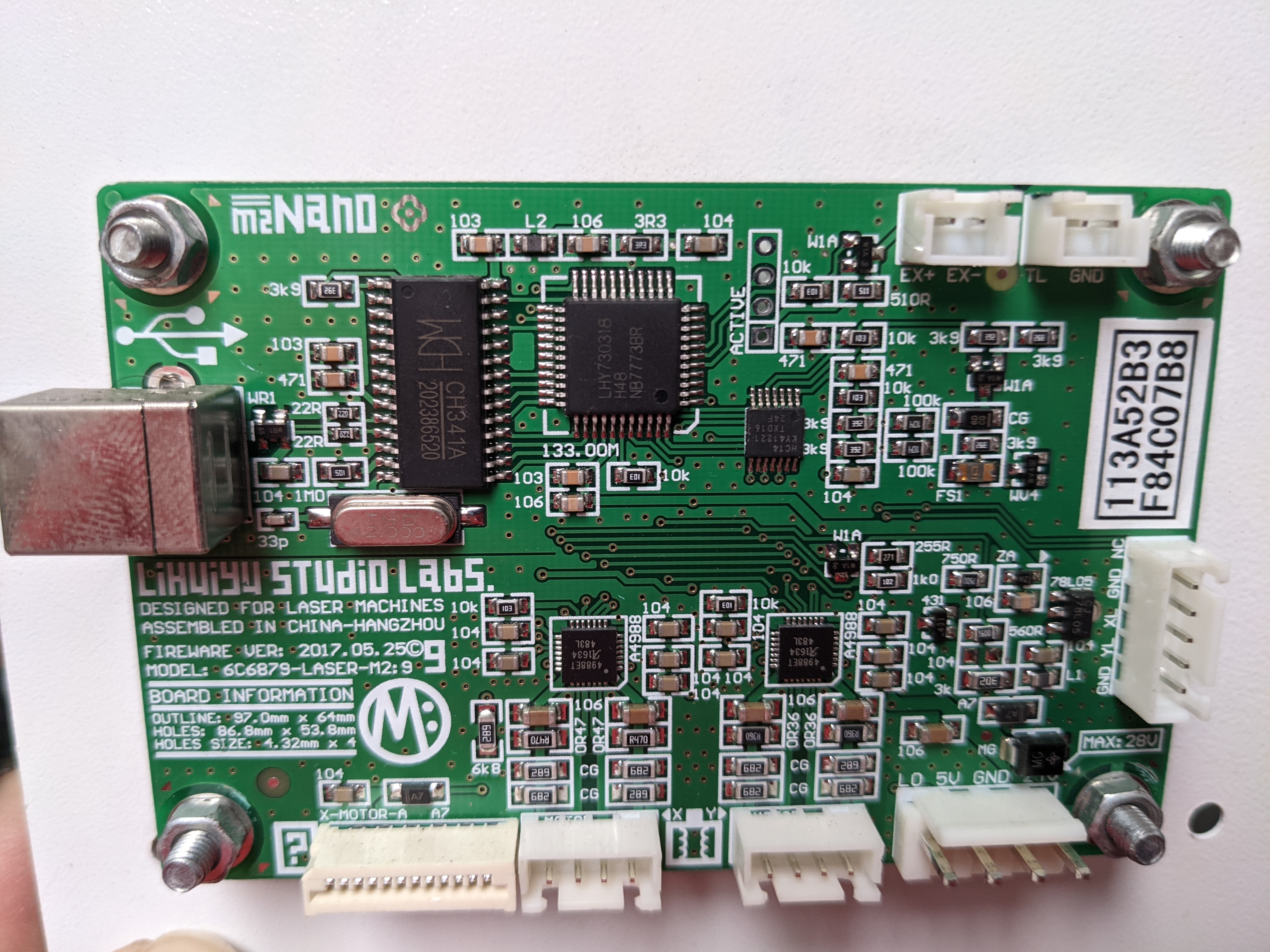
| 6C6879-Laser-M2:9 | 2015.010.15 | LM317 | yes | NC | N | Y | N | Y | 2x 317, 5V is derived from 24V |
Lol. What a mess. So, there’s a green V9 from 2018, a green V9 from 2016 (DRV), and a blue V9 from 2015. And the blue and green non-DRV V9 versions aren’t even the same.
I wonder if at least the “firmware ver” date can uniquely identify them.
I thought I had the same green 2018 V9 as the one in dougl’s pic, but nope, mine’s not a 2018.06.18 V9, it’s a 2018.01.08 V9.
Just to add more data, my M2 Nano is a green board 6C6879-Laser-M2:9 with 2016 firmware and the layout appears to match Don’s 6C6879-Laser-M2:9 with the 2015 firmware. 5V derived from the 24V.
If yours is like mine & the 5V-in pin is not connected to anything?
Theoretically you could disconnect that 5V connection from the LPS and is would still work!?
Yea the 5v isn’t connected to anything on mine either. I’ll try disconnecting the 5V to verify.
LOL … An M2:9 only with a 7805 and no 5v to the end-stops. Clearly the model # does not capture the hardware version!!!
On my board, when I powered from 24V in, I measured 4.? volts on the end stop pins so there some some thing there even if pullups through the uCPU.
The community could benefit from tracing this board to a schematic.
That’s not on my list… especially now that there are so many versions… and I do not use it…