I have Limit switch electrical noise. and I am looking for how to solve that.
I found that one.
Is that working that way? Is it true?
I have Limit switch electrical noise. and I am looking for how to solve that.
I found that one.
Is that working that way? Is it true?
How do you know you have noise?
Input RC filtering is a conventional way to deal with noise.
However, the values will depend on what frequency you are trying to filter out.
As a reference, my CNC controller uses .22uf and 2.7K.
I don’t exactly know what frequency I wanna filter (cos i dont have a tool for it) but what i know is i am getting fasle limit alarms randomly.
and I am trying to find a solution for it. ![]()
What about use ethernet cable?
is that a good solution for it ?
Twisted pair is a good method of wiring sensors, especially over long distances.
I would add the filters as close to the Arduino as you can.
Also, consider…
In my experience noise like this is often the result of:
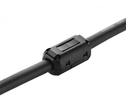
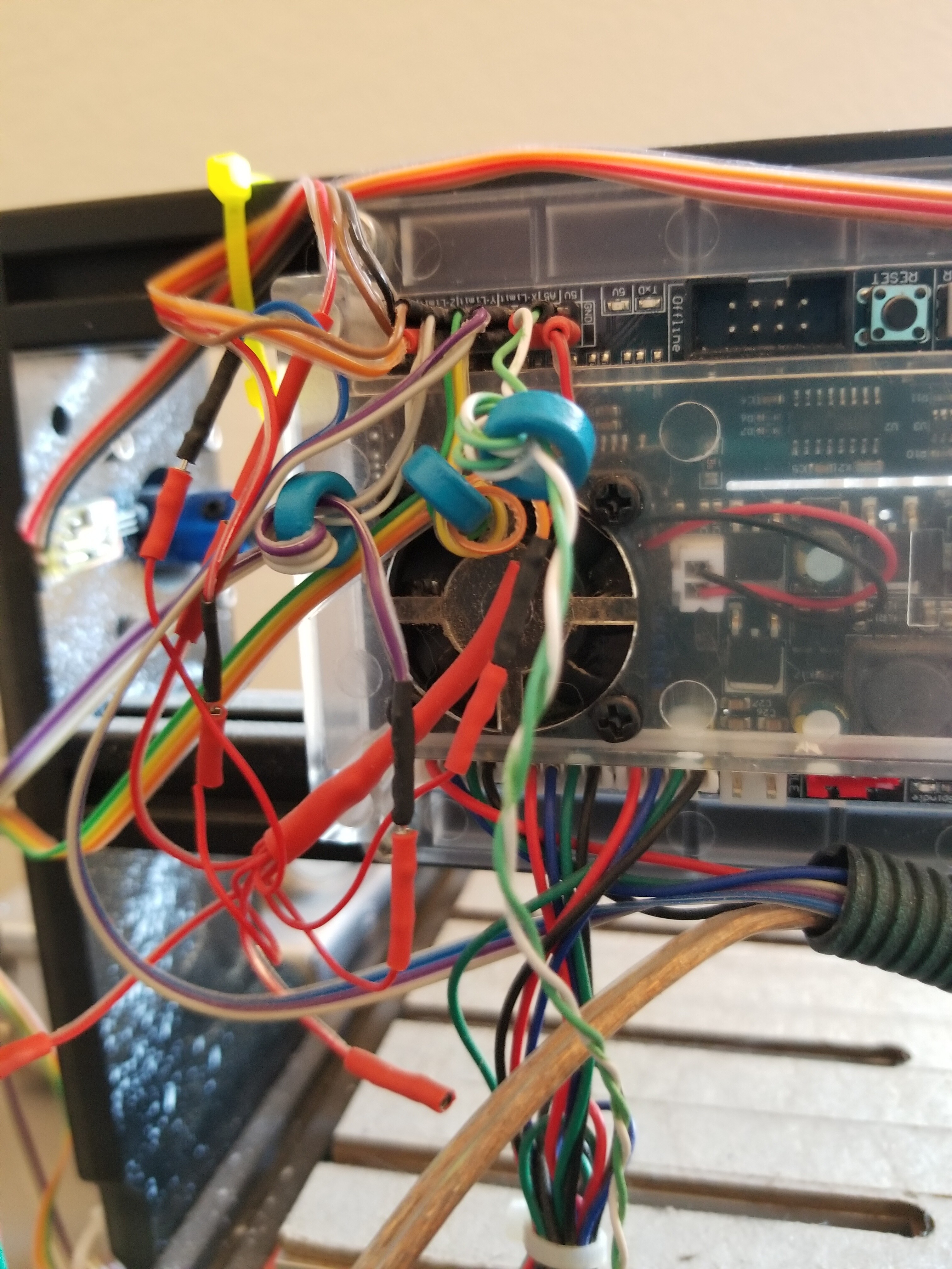
When I first installed limits, I had put protection in the wiring ‘nest’ as it was close to a birds nest… They are the blue ferrite cores that I looped the twisted pair through. I found I didn’t need them, but they are a cheap approach to suppressing rfi.
If I had this issue with mechanical switches, I’d run +5v to the NC position, no interference is strong enough to overcome a direct 5v connection. Ditch the r/c network. Ensure they are ‘break before make’ switches then you should be good.
I purchase some from Amazon, didn’t specify, but they were break before make.
Good luck
![]()
Not my experience at all… high-speed currents and poor grounding can shift both supplies and grounds at high speeds. This noise can be conducted and/or radiated noise. This is why filters are ideal for insuring that high-speed noise of whatever type is attenuated. None of this overcomes bad grounding.
Are you saying this because you think the contacts are arcing?
If there is anything that pulls the supply voltage down to an identifiable ‘low’ state, I’d expect the machine to reset.
If they don’t ‘break’ first then you could apply 5v to ground. It’s easy to check with a ohm meter between NO/NC connections.
![]()
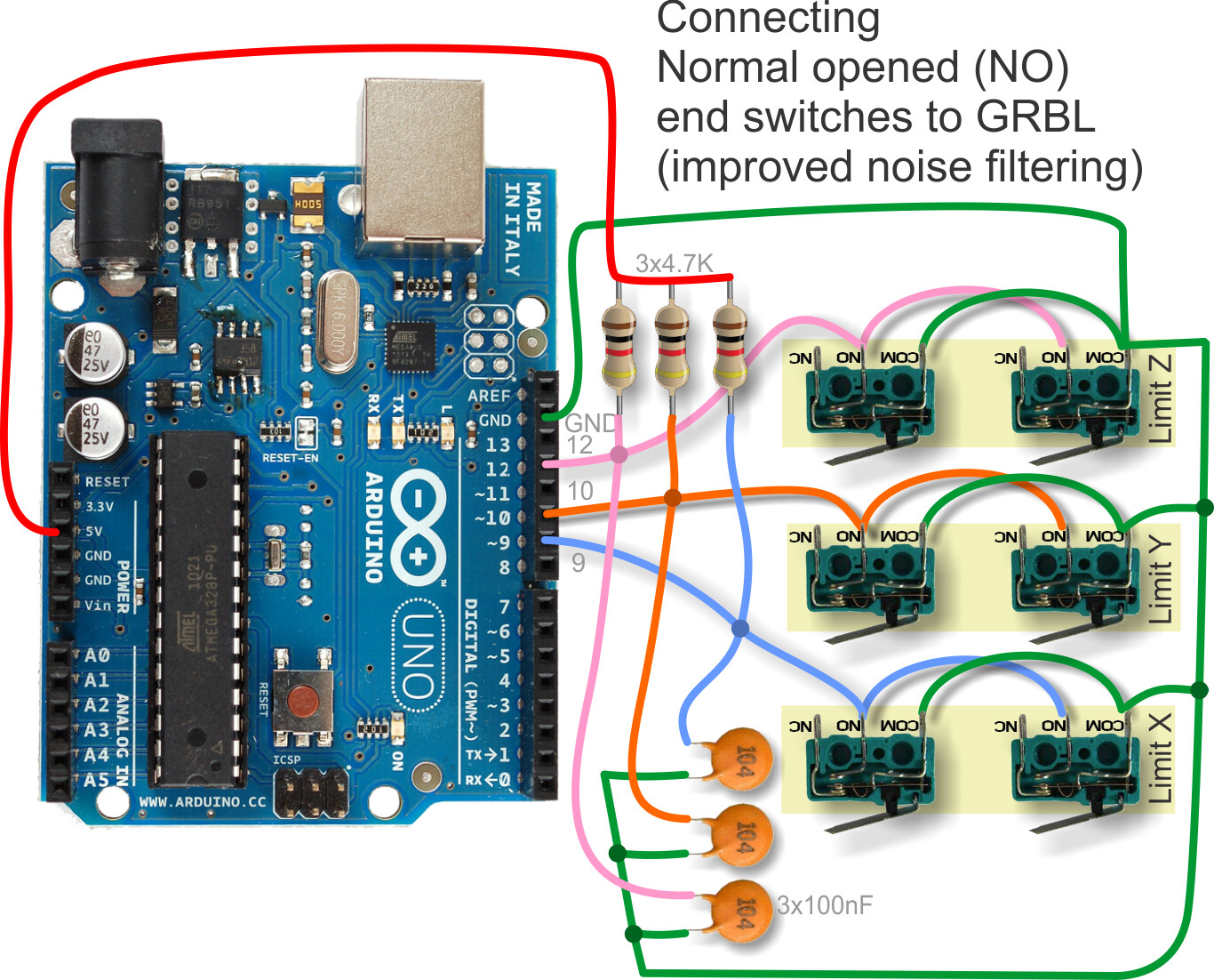
I realize that drawing is a Fritzing pictorial, not necessarily how you will wire it. But I must mention that dressing the wires (ie, where you place them) is very important. As drawn, that entire outside loop of wire is just begging to pick up inductively from motor currents.
Most of these are viable suggestions for the issue. The shortest ‘wire’ will be less of a problem as it’s resonance is at a higher frequency, so keep them as short as possible. If you have a spindle, they draw lots of current. If possible figure out which switch is having the issue.
IMHO I think you need to reverse that…
They’ve used capacitors across points in cars forever (at least as long as we had points) to prevent arcing when the points open or ‘break’. The capacitor ‘looks’ like a short when the ‘switch’ opens and eliminates the arc, extending the life of the points.
![]()
Fyi: cat 5 “patch” cables use stranded wire so they can be put in cable chains.
Make it a good day!
Don
No kidding? They are not single strand wires anymore or is it the “patch” nomenclature which is different from what I think of as typical CAT5 cable?
Not the same. With points in a distributor, current when the points close is due to discharge of the capacitor, but the capacitor/condenser is there to prevent a large voltage from appearing across the points as they open, due to inductive kickback. So the points still erode somewhat from discharging the condenser, but are saved from the much worse erosion that would happen from arcing across the points.
With this circuit, there is no inductive kick, so you aren’t looking at a trade-off. Just contact erosion from capacitor discharge as the switch contacts close. The points in a care are MUCH more robust than those in a microswitch or pushbutton.
They are still not rated for continuous bending, such as you’ll find in a cable chain. For that, you want much more finely stranded wire.
Not rated, but… I’d expect cable chain to spread out the bending to not be sharp bends, and thus practically limit work hardening? I use stranded ethernet cable for my limit switches. I fold the strands back over the insulation at the end and crimp a small ferrule on so that there is no sharp bending load in the termination.
What kind of wire do you use?
Test lead wire. Silicone insulated, 100 strands.
I tend to overbuild things…
I’ve used ribbon cable before, but the kind meant for dot matrix printers. The wire is more finely stranded than generic ribbon cable. Old IDE cables are too stiff.
I have been using the stranded Cat5 for years in moving apps. without any challenges.
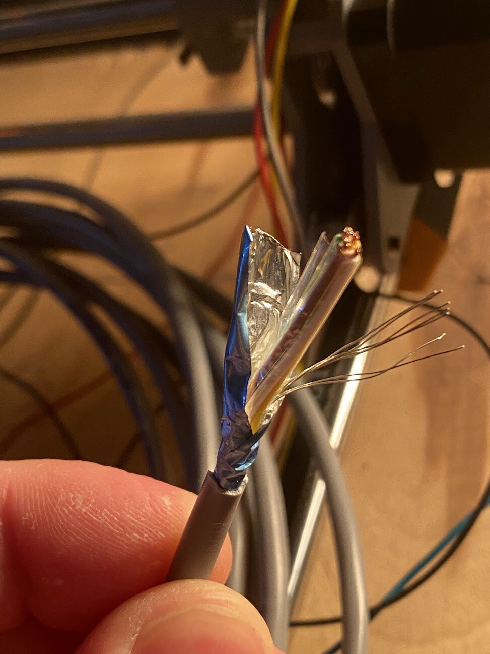
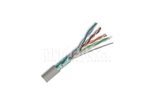
Yes, that’s a shield. Note that the shield should be connected to ground only on one end, by the controller where you should have a single point to which all grounds are connected. Don’t use the shield as a return path for a switch, either.
What kind of filters ?
Like this??