My son brought the Freehand snatch block set we made freehand camping, and it made me curious about improving the design, as I documented in that thread. I got out FreeCAD and got to work. Weeks ago, my son and I machined a press fixture to make precise bends carefully located, and today we finally got back to the project. Here’s the end result:

What follows is a build log for your entertainment. This design has not been analyzed by an engineer, and I honestly don’t know how strong it might be. Also my build technique probably made it less strong than it could be. We will not use this in any way that puts health or property at risk if it fails.
If you have an actual need for such a device, I recommend the SMC CRx Crevasse Rescue pulley (also available at REI and at Amazon) which is advertised to support a person. It’s not even expensive.
But for your entertainment, here’s what we did.
We started by super-gluing two pieces together.

We used the mill vice to align the edges while the superglue set:
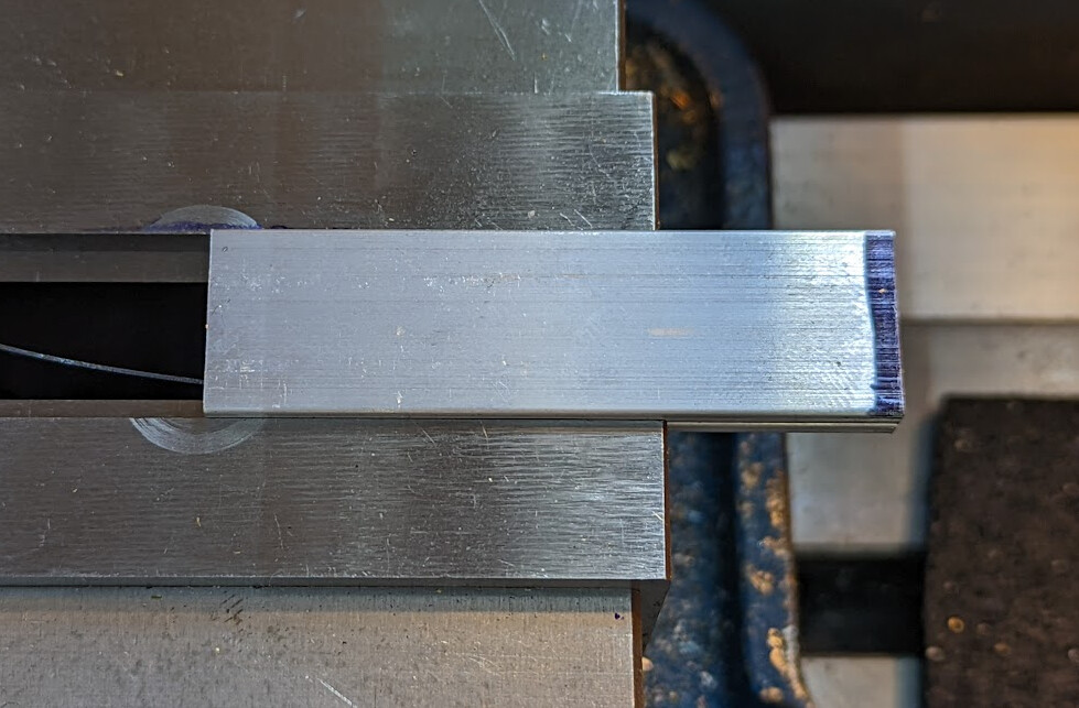
Then we drilled precisely-located 5/16" and 1/2" holes.

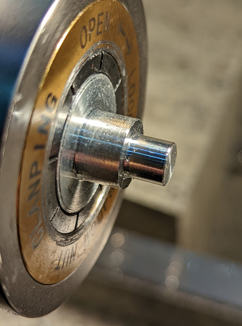
On the lathe, we made a fixture out of a scrap of 1" aluminum rod, with a 5/16" and 1/2" section that each hole in the stack of two glued pieces fits on:
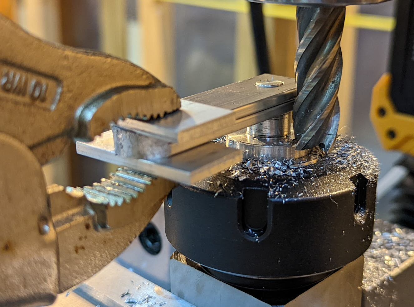
We put the fixture into a collet block, zeroed the quill over the center of the fixture, then offset the mill to the right of the fixture. We set the end of the end mill below the 1" face of the fixture, and then moved the table back until the mill touched the glued bars.
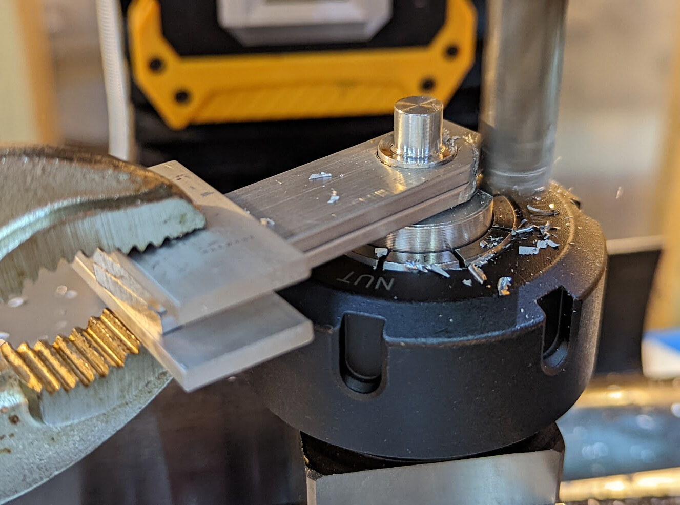
We used scrap to hold the bars with vice grips, turned on the mill, and milled conventionally around. Halfway, we stopped the mill, flipped the part, and did the other side. (We didn’t climb mill because that can grab the part.) Then we repeated the process with the other hole.
We hit them with a torch to break the super glue, then used acetone to clean them up.
Over to the hydraulic press with the fixture. I forgot to take a picture of bending the first side, but then it was a matter of flipping them over and sliding them over (in each case using a block to transfer the registration face up to the parts).
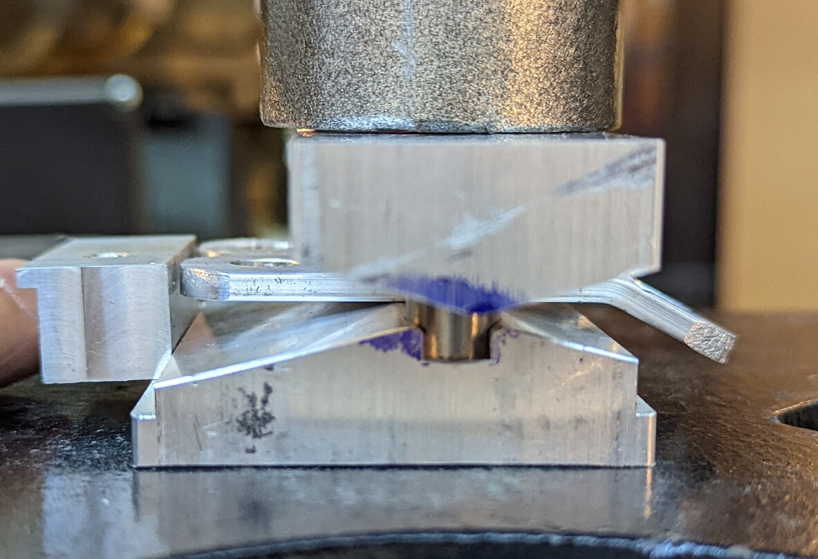
I also don’t have a picture of the completed work still in the press, but the angle in the block on the top is the desired angle plus springback for aluminum. The shiny bit inside the groove is an 8mm polished rod, one on each end, to guide the parts together. We just ran the press until the bent pieces both had bent all the way.
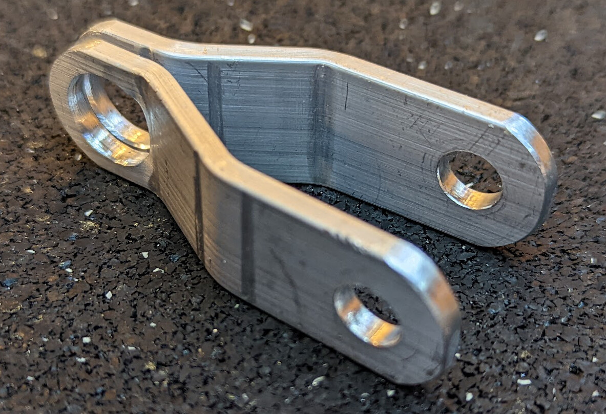
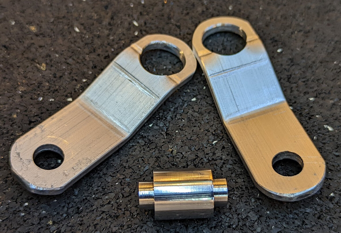
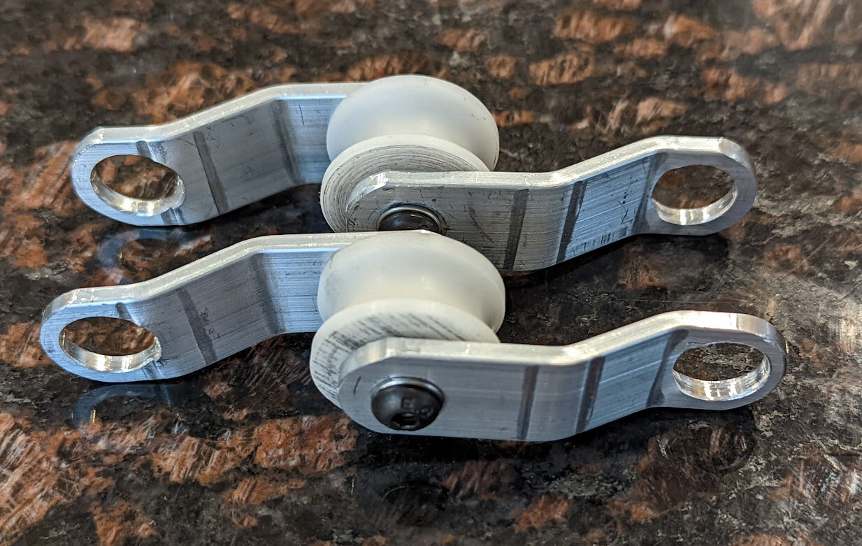
We deburred and filed, and especially rounded the outside edges of the 1/2" hole that rope might go through, to try to avoid rope damage.
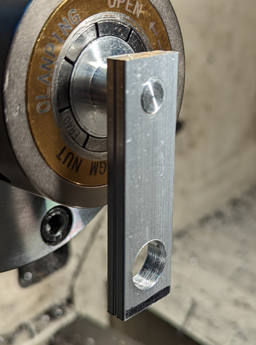
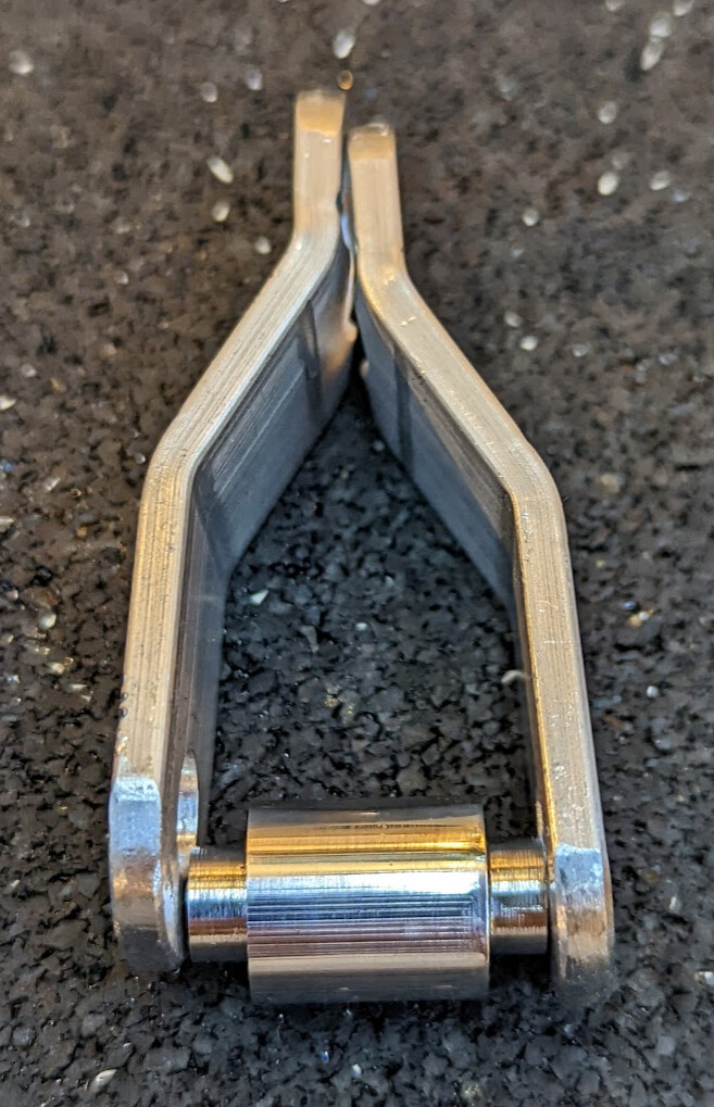
When we were done, we had a pair that looked like this:
On to the shaft.
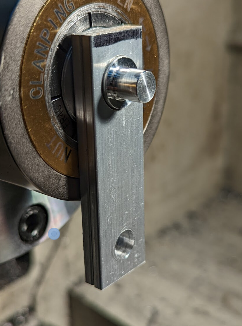
We cut a 5/16" shoulder just over 1/8" deep in one end of a piece of 1/2" aluminum, and polished it bright.
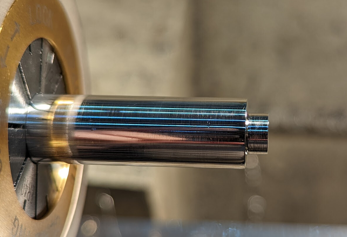
Then we parted it off to length, flipped it end for end, cut another shoulder, drilled it 4.2mm, tapped it M5 through, and polished the new end.
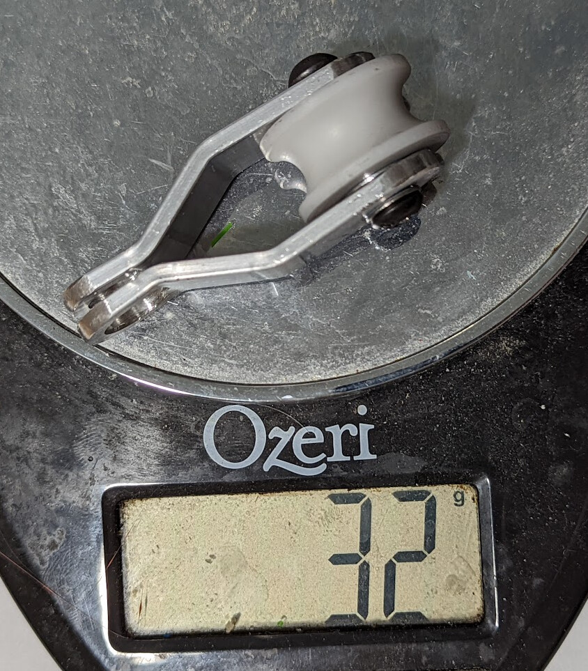
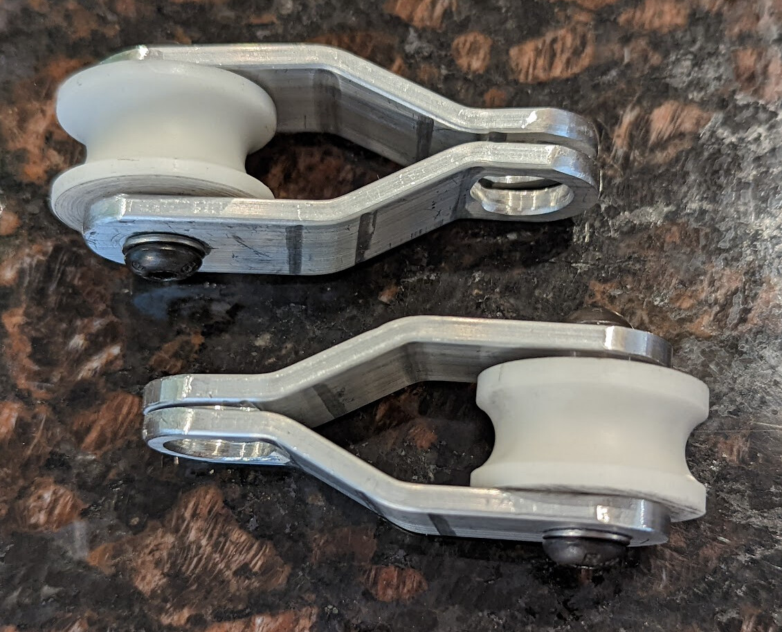
We reused the pulley we made when making the freehand set, and assembled the whole thing with M5 washers, M8x5 button head screws, and a dab of loctite in each end.
![]() 32 grams total
32 grams total ![]()
Lather, rinse, repeat:
All in all, a fun and successful father/son project.
If you’d like to see our design in FreeCAD, you’ll need FreeCAD 0.20 with the Assembly4 workbench installed.