Can you post large, clear photographs as well as the drawings please?
Please describe what exactly is not working?
YOUR SYSTEM:
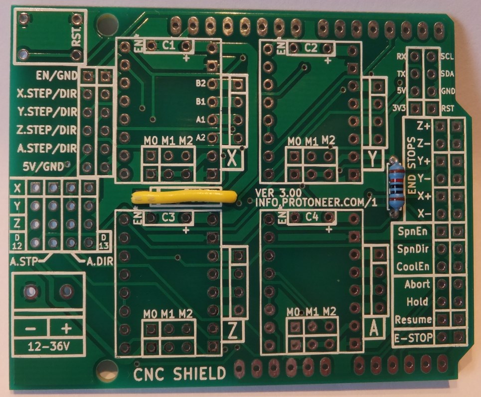
You are using this shield:
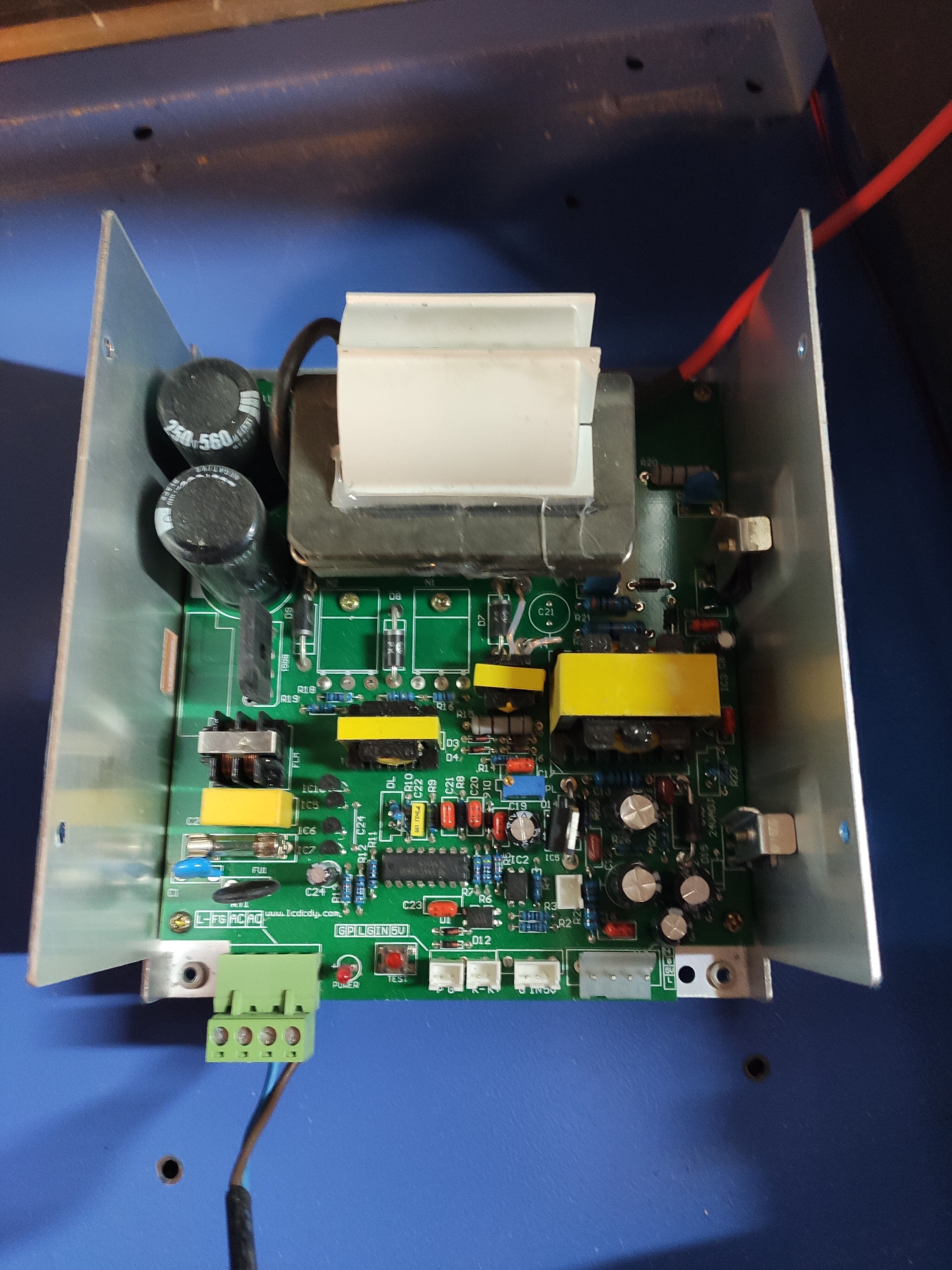
This is your LPS:
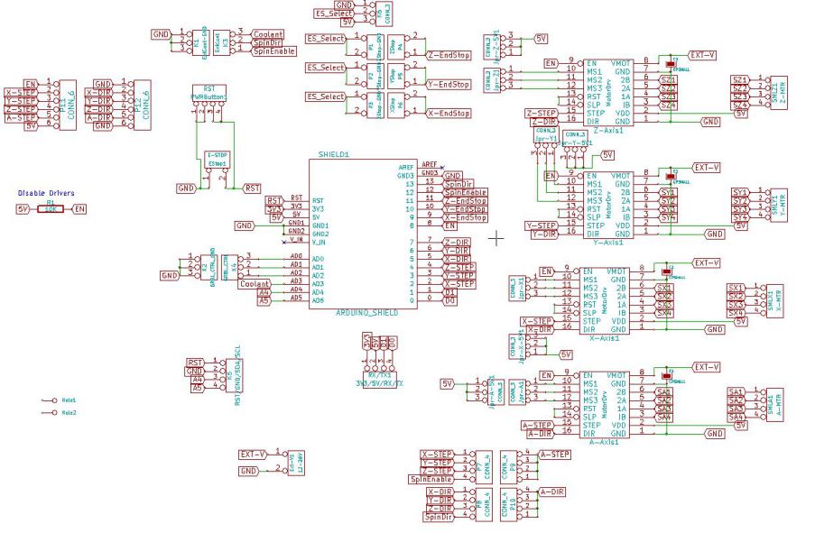
** You’re connected to the LPS like this:**
----Wiring table -----
| From | PinName | Function | To | Pin |
|---|---|---|---|---|
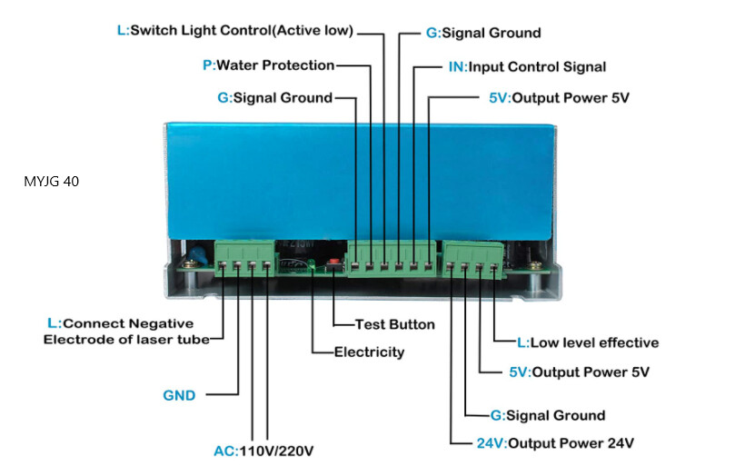
| Sheild | Z+ | Power Control | LPS | IN |
| Sheild | Z+gnd | ground | LPS | G |
| LPS | L | ground | LPS | G |
| LPS | P | ground | LPS | G |
From GRBL:
Laser Mode Operation
Enabling or disabling Grbl’s laser mode is easy. Just alter the $32 Grbl setting.
To Enable: Send Grbl a$32=1command.
To Disable: Send Grbl a$32=0command.
When laser mode is enabled, Grbl controls laser power by varying the 0-5V voltage from the spindle PWM D11 pin. 0V should be treated as disabled, while 5V is full power. Intermediate output voltages are also assumed to be linear with laser power, such that 2.5V is approximately 50% laser power. (A compile-time option exists to shift this linear model to start at a non-zero voltage.)
@cprezzi are you familiar with this type of Grbl connection. To me, looking at the sheild, it looks like the Z end stop which is Arduino D11 {a PWM pin} is used for the LPS-IN pin connection. Is this correct??
all right what you wrote, power supply and schematic same as my schematic, parameter grbl $ 30 = 255
when i tried to cut plywood 3,5mm at 100mm / s full power 255, i couldn’t cut, i didn’t understand why, i abandoned arduino 1, in 20 days comes mks sbase LPC1768
The controller is imaging correctly just at to low of power?
Google translate:
Il controller sta visualizzando correttamente solo a bassa potenza?
i can tell you that i used short while arduino 1, i took off after 10 minutes, could it be the problem original k40 power supply that has no strength?
There are many things that can cause a K40 to have low power such as:
- Poor alignment
- Dirty optics
- Misaligned head
- Bad LPS
- Bad tube
Ci sono molte cose che possono far sì che un K40 abbia una bassa potenza come:
- Cattivo allineamento
- Ottiche sporche
- Testa disallineata
- Cattivo LPS
- Tubo difettoso
If the machine is imaging properly there are other things to check before the controller.
Se la macchina esegue correttamente l’imaging, è necessario controllare altre cose prima del controller.
Please post a picture of what the output looks like.
Si prega di pubblicare un’immagine di come appare l’output.
I wrote all (no) because with original power supply and m2nano card it works well k40, I go to sleep, Italy 1 at night, thanks DON
See below I need these actual pictures to be helpful.
Vedi sotto, ho bisogno che queste immagini reali siano utili.
I’m sorry I can’t take the photo, I took off arduino
@marcy I do not recomend the schematics from your fist post with the Arduino PWM out connected to the LPS IN. Instead I recommend connecting the potentiometer to GND / IN / 5V (like original K40) and use the L pin for the PWM signal. And because the L pin is inverted (active low) this means you would need a Mosfet to invert the PWM signal. Please see:
2 Likes
thanks for the tip, a mks sbase lpc 1768 is coming, i will connect this board.
do you have an easy scheme to connect potentiometer to mks sbase with original k40 power supply?
ps: i saw that you made grbl-lpc, are you an italian guy? great pleasure, i’m from milan
traduzione italiano
grazie per il suggerimento,è in arrivo una mks sbase lpc 1768,collegherò questa scheda.
hai uno schema facile per collegare potenziometro alla mks sbase con alimentatore originale k40?
ps: ho visto che hai realizzato grbl-lpc,sei un ragazzo italiano? tanto piacere,io sono di milano
I suggest to install and configure the mks board first with the original smoothieware firmware. When doing so, you should use the bed mosfet output (minus pin) connected to the L pin of the LPS. This way you can connect the original K40 potentiometer (if you have the analog panel) to G, IN and 5V of the LPS to set the maximum laser power.
When it’s electrically working you can decide if you want to change the firmware to grbl-lpc. There are pros and cons to do so. Pro is, that you can reach much faster raster engraving speeds, con is, that you loose the option of a display (which smoothieware supports) and the easy config file of smoothieware.
PS: My father was italian, but I can’t really speak italian.I live in Switzerland, near Zürich.
1 Like
The best firmware to use on that board would be the smoothiware clustering firmware that Cohesion3D uses on their boards. It works on all smoothieboards and actually out performs Grbl-lpc when using LightBurn with it. (Unfortunately LightBurn is required to use the clustering feature that improves the gcode throughput)
2 Likes
sorry I didn’t write that my k40 is digital, I’m interested in firmaware grbl-lpc because I know my brother well, can I put analog potentiometer on the mks sbase with your firmaware?
can i connect analog ammeter with mks sbase + grbl-lpc? or digital ammeter still works?
can I put analog potentiometer on the mks sbase with your firmaware?
Yes, an analog potentiometer can be used in conjunction with the MKSBase as the power control of the LPS using a potentiometer is independent of the controller or its firmware
can I connect the analog ammeter with mks sbase + grbl-lpc?
Yes, because the two are unrelated
or the digital ammeter still works?
What digital ammeter are you referring to?
my k40 has the digital panel, does the digital panel still work with mks sbase?
or should I put Analog ammeter with mks?
my k40 is this https://www.amazon.it/gp/aw/d/B07ZGMRRQS?psc=1&ref=ppx_pop_mob_b_asin_image
See New to K40: Start Here — it doesn’t which panel you have, you want an analog ammeter. See Don's Laser Cutter Things: Replacing the K40's Digital Panel with an Analog one
3 Likes
YES; You can add a milliamp meter to your machine with any type of controller and the digital panel.
Yes, the digital panel works with any controller you choose.
To be clear:
The digital panel:
- DOES NOT in any way connect to the controller.
- Controls the laser power by providing a fixed signal to the LPS-IN pin proportional to the panels % power setting
- Does not have a milliamp meter and in no way connects to one if it is added
- Does not in any way measure laser current. The digital panel and the milli-amp meter are two separate things
The potentiometer:
- The potentiometer replaces the function of the digital % power display and buttons.
The Controller:
- When connected like @cprezzi suggested, provides a dynamic power control signal to the L pin of the LPS only when a job is running.
- No other connection is made to the LPS, milliamp meter, or digital panel from the controller.
- The controller operates independent of the digital panel and the milliamp meter
Suggested Starting Configuration
- Use the controller wiring @cprezzi suggested. [this will control the laser during a job]
- Add/mount a milli-amp meter to the machine somewhere [this will measure laser tube current]
- Leave the digital panel alone [set static power settings using digital display and associated buttons]
Once this configuration is working you can consider adding a potentiometer.
More detail about the digital panel here:
2 Likes