Laser glitching around text

Are you telling me that the Power Control Input( LPS-IN ) is getting a varying TTL square wave, ie having pulse width modulation? The Power Control Input?

I must have missed when that was stated because I thought it was just a fixed period and fixed duty cycle signal used only to set the max power output of the LPS. If so it’s just not anything any of the other controllers( non Ruida ) take advantage of and if there were a benefit I would think the developers would have jumped on it long ago. Many systems just put a stable DC voltage on that Power Control Input( LPS-IN ).

Now the other signal is what/where I thought all the magic happened with regards to controlling how the laser was putting marks on materials. And that signal LPS-L or LPS-H and labelled as Laser Switch(0V and 5V) enable on the Cloudray picture. There, an ever changing pulse train is output by the controller and controls the pixels being marked on the material by the laser.

Personally, referencing the signals by the LPS names/labels makes more sense than mixing labels by controller output label and LPS label. Many here are far more familiar with the LPS-IN and LPS-L labeling used on LPSs found in K40 and K50 machines.

Unfortunately none of this discussion is eliminating any part of the system from the problem originally stated…

Yes, that’s the original lps design. There are really two inputs to control the lps. IN is the power control. L is to enable the laser to lase at whatever power level IN is set.

  • K40
    • pot → IN
    • pwm → L
  • Ruida
    • pwm → IN
    • L-On → L

When laser enable goes low the laser will fire at whatever the IN setting is. If the IN pwm is 0% then the laser will not lase. If it’s 50% it will be ‘on’ 50% of the period.

Take a line as part of a fill. On a single pass, when it gets to the proper place the L input goes low and it stays low until the line is complete. The laser is lasing at the IN or pwm rate. The L input is active for a longer period than the pwm or power is set. You get an average ‘power’ over the time L is low.

The K40 sets the pwm on the IN pin, usually with a dc voltage. This is a pwm setting within the lps and is equivalent to feeding a pwm signal to that pin like the Ruida does.

The K40 now uses the pwm to enable the laser. When the pwm is low on the L pin, the machine lases at whatever the ‘pot’ setting (pwm) has been previously set. This is what limits you mA and gives you the ability to set 100% with the pot. When the pwm from the K40 is applied to the L input it enables the laser for that period, which lases during that period at the IN setting.

Does any of this make sense ?

That may apply to you and yours that hang around with the K40 crowd and own one… It took some thought to figure out what the h**l the K40 was doing the way it was wired up. It seemed bassackwards.
Realized it had to do with money, :poop:

@donkjr was instrumental in helping me understand what’s going on with the internal workings of the lps and the K40 interface… at least the tip of the iceberg. :thinking: I thank him everytime I see his icon :+1:

A big part of this was being able to get my scope on it and actually watch it. At least the control signals.

Laser ... enable” == “laser enable

All the L input does is ‘enable’ the laser to fire at the IN ‘power’ level.

:smiley_cat:

So on the Ruida the “pwm → IN” signal is a varying pulse width modulated TTL signal?
I figured it was equivalent to the fixed DC voltage often used with K40s with GRBL or Smoothieware firmware so that LPS-IN is set once and never touched again… But I guess Ruida does this differently and instead of a never changing 2.5DCV the Ruida puts out a 50% duty cycle pulse train for some period of time and changes this when the layer change in the design has a different power level. I didn’t see that in your Oscope screen shots but then again it was a very small window of time.

That is quite different from how the K40 GCode based controllers drive the LPS. Besides, I thought from your Oscope traces the laser was burning at different intensities because on each pixel the PWM signal put on LPS-IN was a certain width which limited how many laser pulses were fired on that pixel. The laser frequency fires at a much higher frequency than the controlling PWM.

If the Ruida had drivers builtin I would wire it up to my K40 and look at this on a scope since I have a Ruida controller in a box but no stepper motor drivers.

If you set the percent power in your software to 35%, it will generate a 35% pwm output from the Ruida to the IN of the lps. It’s set from the executing layer.

With the K40, you are setting the pwm with the pot and turning the laser on and off with the L input, with the K40s pwm.


I have lots of questions about how parts of this works. Most of it is not easily found or measured. I’ve noticed the hv is present if the tube is lasing or not. I’m suspicious that it’s there and only increases enough to let the tube start conducting.

Also keep in mind that the speed you can put down ‘dots’ is dependent on the lps response time.

Motor drivers for the Ruida are about $22 each, last time I looked…

:smiley_cat:

The stock K40 with the M2Nano controller is that way and the only ‘gray scale’ like control was via dithering. But once you replace the stock controller with one which does a different PWM on LPS-L then we are able to do grayscale even though LPS-IN is fixed at some maximum power output level. I don’t know the specifics of what’s happening on LPS-L but anyone with a Cohesion3D board or any Smoothieware based board and even GRBL firmware can do power control off of one PWM signal going into LPS-L while LPS-IN is fixed at some maximum level and everything below that is 100%-0% power range set in LightBurn.

Sounds like the Ruida is more like the M2Nano but with digital control on LPS-IN to set the power level per layer. And I’m surprised if that were a better way, why are none of the open source firmware developers doing this. odd.

  • In this case the power level = DF(internal LPS) * DF(pwm-L) ;
  • Both PWM’s control power. This means that the product of IN and L DF determines the power. The L in this case functions as an enable and part of the power control.
  • There is no enable other than the PWM-L signal not being asserted [DF =0] .When no imaging is active the laser is off.

In this case the power level = PWM-IN
The enable is L. So I assume that this line is asserted for the entire time an image is being created. However, I have not measured such.


I think the IN was intended to be an analog control and the L is the digital on-off control.

As I understand it the original K40 only dithered so all that was needed was an intensity control pot and an on-off function.

When we replaced the NANO controller with Gcode control the debate about how to use the IN and the L arose. Actually, that is what prompted me (and a few others) to fully document the LPS design

It appears in the Ruda application the IN was chosen to control power with a PWM and the L as the enable.

In my experience controlling power only in the source imaging program ignores the need to adjust for tube changes. To each his own.


I wonder if all this dialog is getting us closer to finding this problem. :confused:

a few of the open source / 3DP controllers have built-in stepper motor drivers but most have sockets for stepper motor drivers so you just purchase the drivers you want and plug them in at a cost of ~$5ea to $25ea on the high end. The motor connections are all done on the main 3DP controller board. The “external” drivers needed for a Ruida setup have a higher cost and much larger footprint mostly because of extra costs of connectors, mounting hardware, plastic casing and labeling.

I picked up a $50 MKS Sbase v1.3 board for my K40 and everything but end-stop wires just moved from the M2Nano to the MKS board. For the end-stop wiring, the M2Nano had 3 pins for the end-stop( X-gnd-Y ) with 2 wires crimped into the one ground pin. The MKS board wanted a 2-wire pair for each end-stop and I could have kept it with the grounds tied on one connector so the other end-stop connector was just the signal wire but I broke them out to X-Gnd and Y-Gnd connections.

IMHO, all of this has ‘evolved’ from existing commercial equipment and changes are made to lower costs for the hobby sector. Those that can’t afford a $20k machine. A friend of mine that supplies my acrylic (scrap) from his commercial business has an American dual laser tube machine with a Ruida controller. His previous laser had a trocen and it was wired the same as my Ruida. It had an accident with acrylic and honeycomb that ended up in a significant fire in his shop.

The most simple interface is one that is already used by existing, more expensive commercial equipment. On a laser the single most expensive part is probably the controller. Most of the early controllers used a variable dc to control the spindle (spindle speed = laser power). I’ve also noticed that many of the newer or lower cost controllers have done away with the analog control.

The Ruida, Trocen and other commercial controllers have been around much longer than the K40 and it’s associated hardware. They also allow you to ‘store’ the code and don’t require a computer to connected to actually control the hardware.

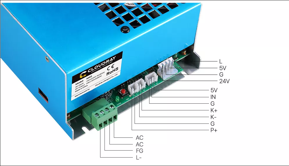
I think the K40 controller is a very cheap, yet ingenious device. Just by leaving out the ‘laser enable’ signal removes a lot of the ‘head ache’ on what the controller/software has to do. They just make the power a manual control. Removing this from automated control greatly relieves that K40s signal interface.

In the end, they both do the same thing, although I have to admit, the K40 controller/software is really an incredible creation. Always wish I had purchased one. Of course my sights are a bit higher now.

The L-On1 → L is active only when the laser needs to fire. Not sure if that’s what you meant. The pwm is separate and runs for the entire time the layer is executing, even while the head repositions itself to lase another object.

Now that Lightburn has ‘sub layers’ it looks like the same thing happens as it switches to a sub layer that sub layers pwm is immediately present.

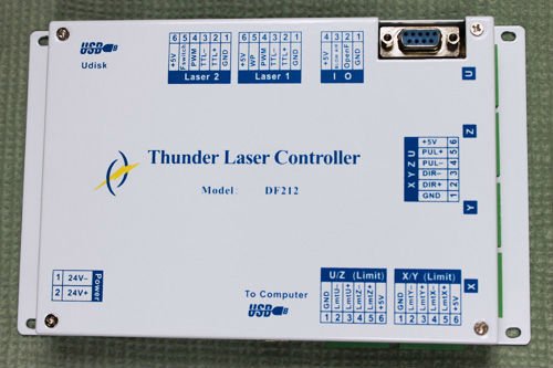
The Thunder laser DF212 only has a pwm output and a ‘ttl+’ and ‘ttl-’ for firing control. The - is for the L input, or it’s inverted + for the H input. No analog output…

thunder-df212

I understand completely, to me, this isn’t the argument.

In a commercial environment when maintenance is paid for and routinely done, this isn’t an issue. It’s also not wanted in a commercial environment. You have a person with no technical knowledge, monitoring the equipment (maybe 20 of them) as it does the same thing over and over. Having an adjustment accessible to the operator that can damage the equipment is the last thing you want around in this situation.

I’ve had mine for over a year, I check it monthly and I have not had to change the lps settings up to this point. I expect to as it gets older, like me, won’t have a much ‘go’. I use a Mahoney wattmeter or Russ’s dohickey…

You, I and most of the people here are not the average user and certainly not the hired ‘hourly’ worker to watch over this stuff…

I’ll have to admit that I have gone into the Ruida console and bumped the power when I get a run of mdf that has more glue in it. A pot may have been handy there.

Also note if you wanted to use a Ruida for an LED laser that uses the pwm to fire the laser, you would have to add some kind of ‘and’ gate to generate the pwm only when L was asserted.

I wish… but don’t think so… Think we ran out of ideas.

The only part of this issue is that there appears to be a ‘fixed’ amount of time that it ‘fails’ in this way. As you change the speed the area that ‘fails’ is closer of further away. So it appears to me the lps isn’t really shutting down. I sometimes wonder is this is something that can occur with the tubes chemistry and is lasing at a lower power level or …?

I was hoping that @dougl could explain more of what he was talking about for an r/c filter… I’d try anything to ID what’s going on here.

I’d still put my money on the lps…

Sorry about the diarrhea of the mouth… I need to get going…

Talk to you later…

P.S @donkjr the hv meter failed. The resistor stack is apparently not working and I am building another one with higher precision resistors. I think the epoxy must have expanded or shrank enough to break the connection. Figured it was the meter, but it works, who’d thunk it was the resistors. Never thought I’d miss it. Also, I have no equipment to measure 600mOhms :poop:

:smiley_cat:

Well, it seems I’m seeing the same issue with my 50W. (KT332N controller)
I was etching a name tag on a plastic gold tone over black name tag blank. Just using the plastic protective film it came with as the masking.

I hadn’t noticed this before, which I theorized was due to the pulses not penetrating my normal masking.

Masked another blank using my normal masking and the glitches are not seen. So if your masking is heavy enough you can work around this if it’s a problem. Still would be nice to have a hard fix.

2 Likes

It should not be ‘pulsing’ in that area of the graphic… I’ve seen this on a few machines. Some show it occurring on only one side if set for unidirectional engraving, instead of bi directional.

You’re right, thicker tape isn’t a ‘good’ fix…

:smiley_cat:

Ok, it’s a random and spurious output of energy of extremely short duration. :crazy_face:

2 Likes

Wasn’t trying to be offensive, but it must be lasing to do that. I’ve seen a number of these and most of them have changed out the tube, controller and lps and have the same issue… It would be nice to know where this originates.

It was interesting on one, where they disabled bi-directional engraving and the aberrant spots show up on the trailing side of the engraving only.

:smiley_cat:

1 Like

No worries, I didn’t think you were trying to be offensive. :wink:
Has there been any commonality relative to the quality of the LPS?

I haven’t seen it fixed but lots of parts seems to have been changed out in many of the instances. One person has had the vendor replace all the main parts. Others have taken a more one shot, like the lps, but no one that I know of has shed any light on this anomaly.

I keep hoping…

:smiley_cat:

1 Like

I seem to remember someone mentioning that it took three different power supplies to finally alleviate the problem on their machine.

1 Like

Yeah, I’ve been noodling through the long thread on the Lightburn discourse.

It’s looking more and more like an LPS issue but nothing definitive yet. Some have found it does this in a narrow power range like 18 or 20% and when they changed power to be outside that range it didn’t product the sparkles.

1 Like

Some people advise not to run at a low power level because you can’t count on the lasing reaction at the low end of the range… I’m wondering if it’s in some kind of ‘more’ excited state. IMHO, it’s a hardware problem, probably not rfi. I’ve gotten my share of ‘bad’ new parts…


One person posted a screenshot from one of the controller makers that recommends raising the minimum power level ($30, in grbl,I think) to somewhere around 5% so the tube would respond faster as it’s kept at a higher energy state… I didn’t buy into it…

:smiley_cat:

1 Like

At or below 4ma the tube will have a hard time ionizing reliably.

2 Likes

Just to close this out, Ed Nisley over on the Lightburn forum posted about what he found and blogged in detail. It turns out that the LPS at low power output( < ~30% PWM on LPS-IN ) has some LPSs sending power glitches on the output even when the Enable signal on LPS-L is off/High. I don’t know if this will show up when the LPS is controlled like a stock K40, ie DC voltage on LPS-IN and PWM on the Enable signal/LPS-L.

Ed’s proof it’s in the LPS as it’s controlled only by Ruida with PWM on LPS-IN and Enable on LPS-L.

Ed’s test rig setup.

2 Likes