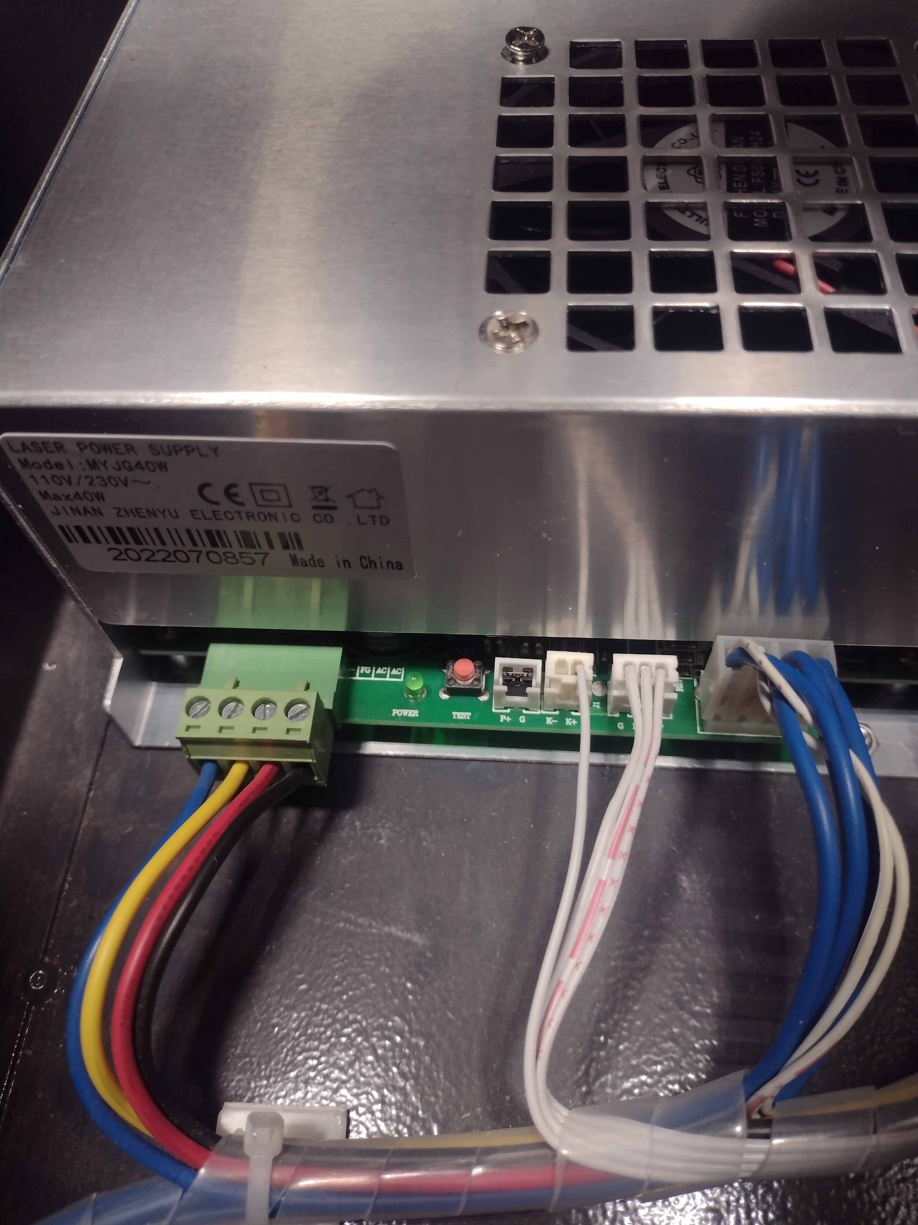
I have recently installed a replacement power supply after the failure of my original power supply. I used an OMTech MYJG-40W. I selected 115V via the slider switch, connected the anode to the laser in the same method as it had been originally installed and plugged in each of the connectors.
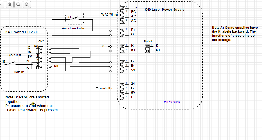
Upon installation, the machine “woke up” and the laser would test fire from the button on the LPS. Loading a job, the machine worked as intended EXCEPT that the laser would not fire from commands from the control board. After consulting some blogs and forums, I realized that the interlock circuit was most likely to blame. My machine is not equipped with any such interlocks. Upon inspection of the original power supply connectors, I discovered that a tiny jumper plug had been installed across the P+/G1. I transferred the jumper plug to the new power supply. Now, when the machine is powered on and the power level is increased much above zero, the laser fires continuously!
Could this be a grounding issue? I went ahead and tried adding a external ground to earth from the grounding lug, but this had no effect.
Did I just receive a faulty power supply? If so, what is your recommendation for a replacement power supply?
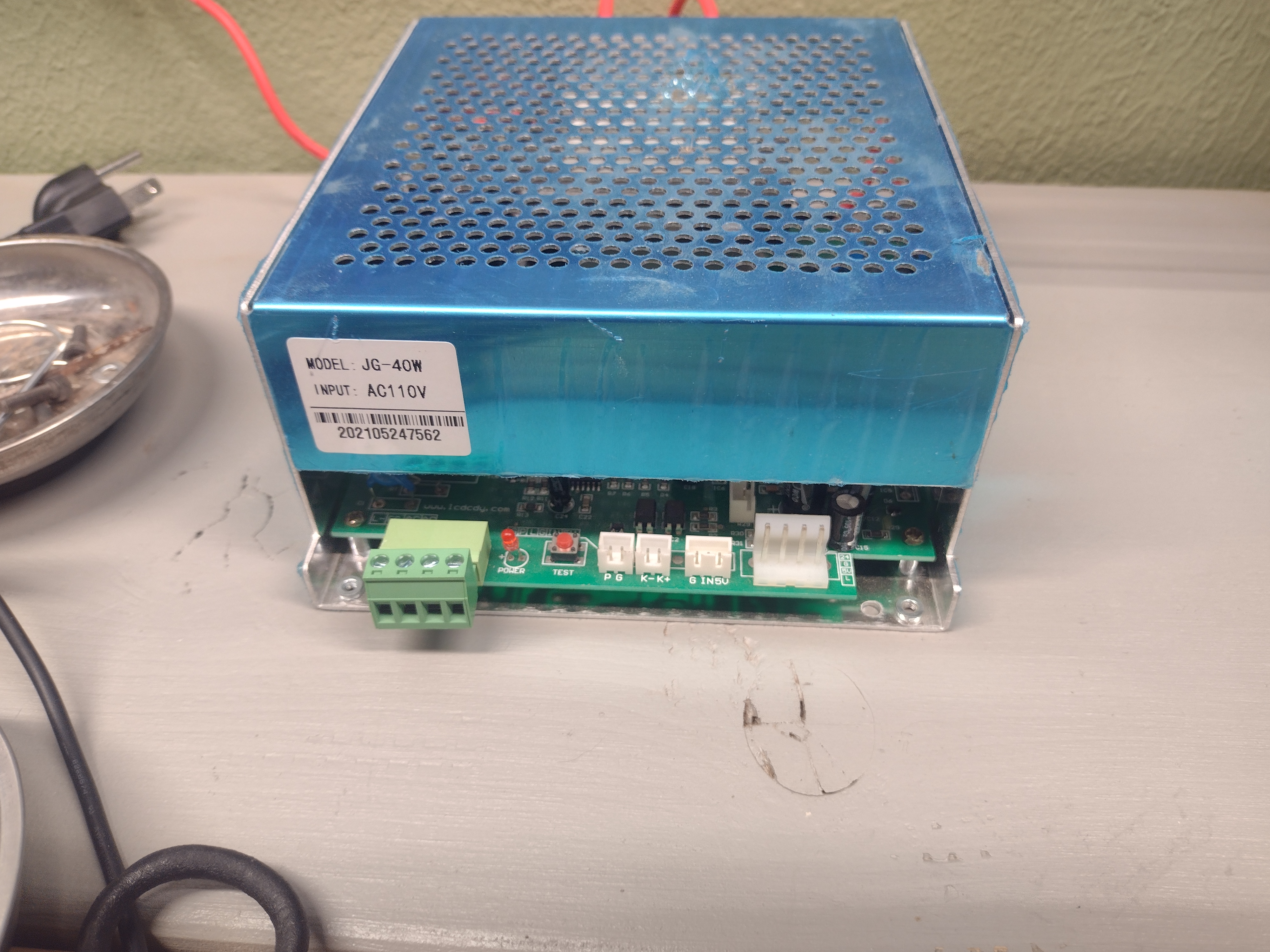
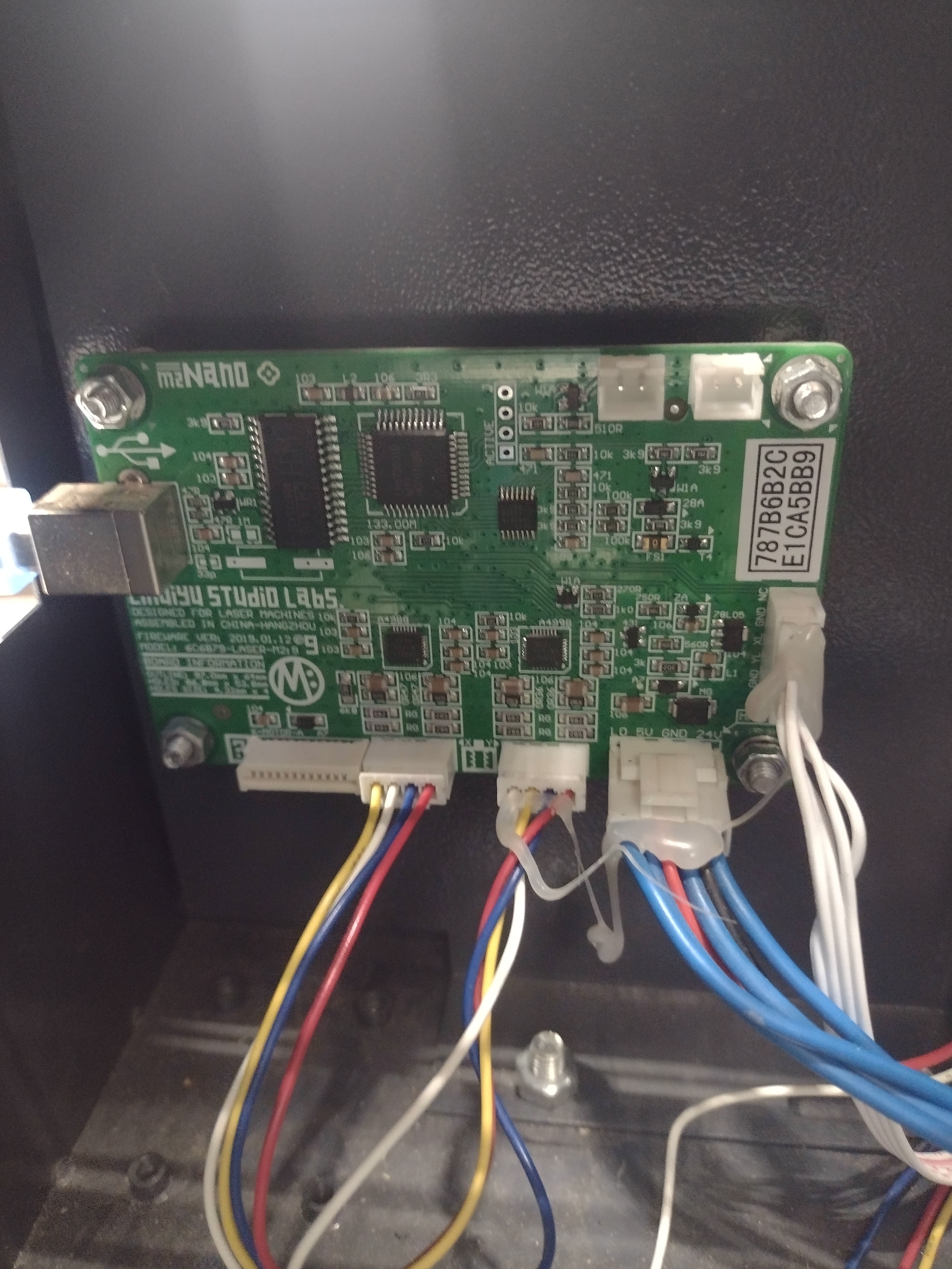
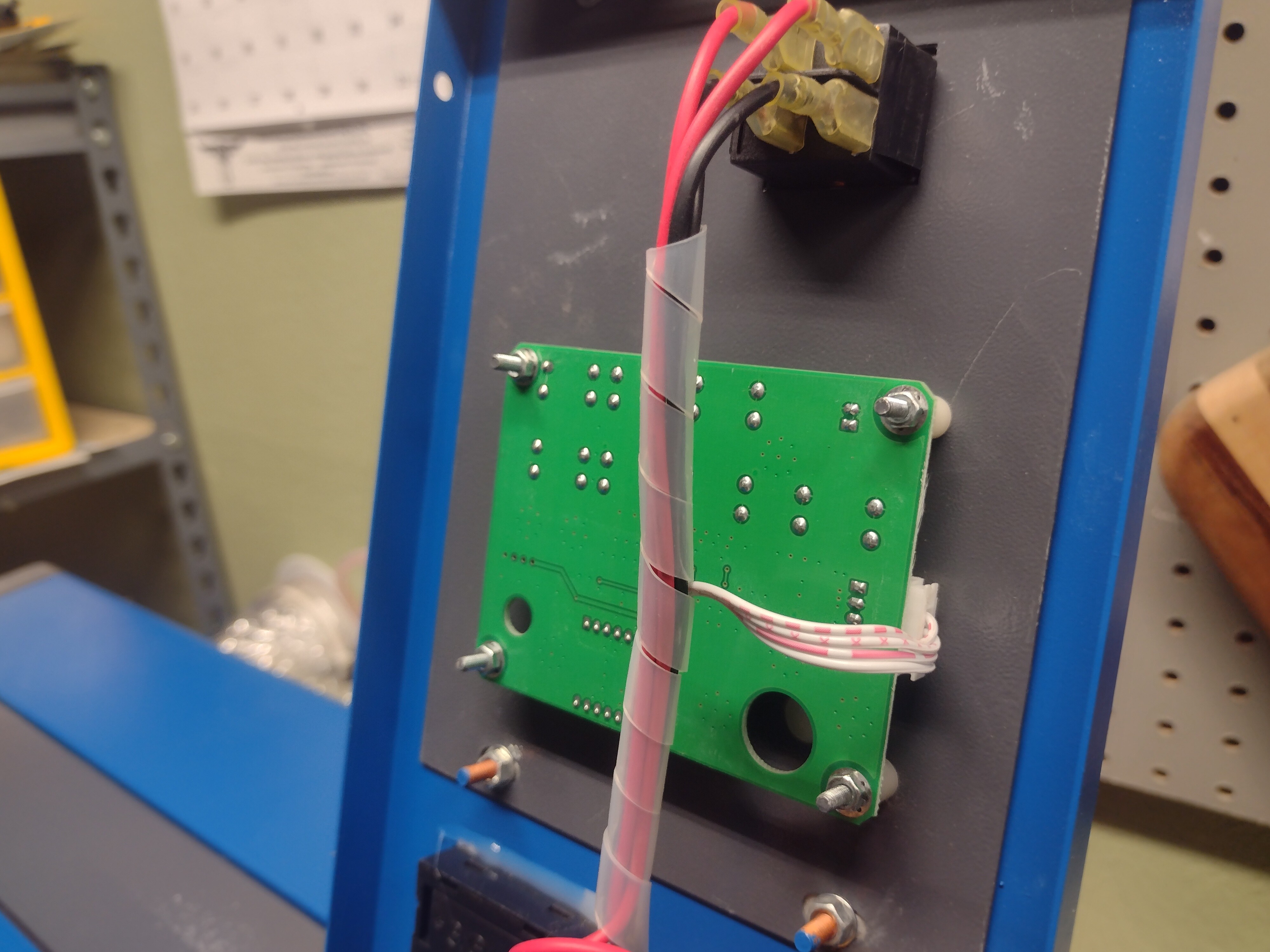
Attached are photos of the new power supply (with black jumper plug installed), the old power supply, and the M2Nano board.
It seems that your digital panel is continuously asserting the laser test button signal (K+ to ground).
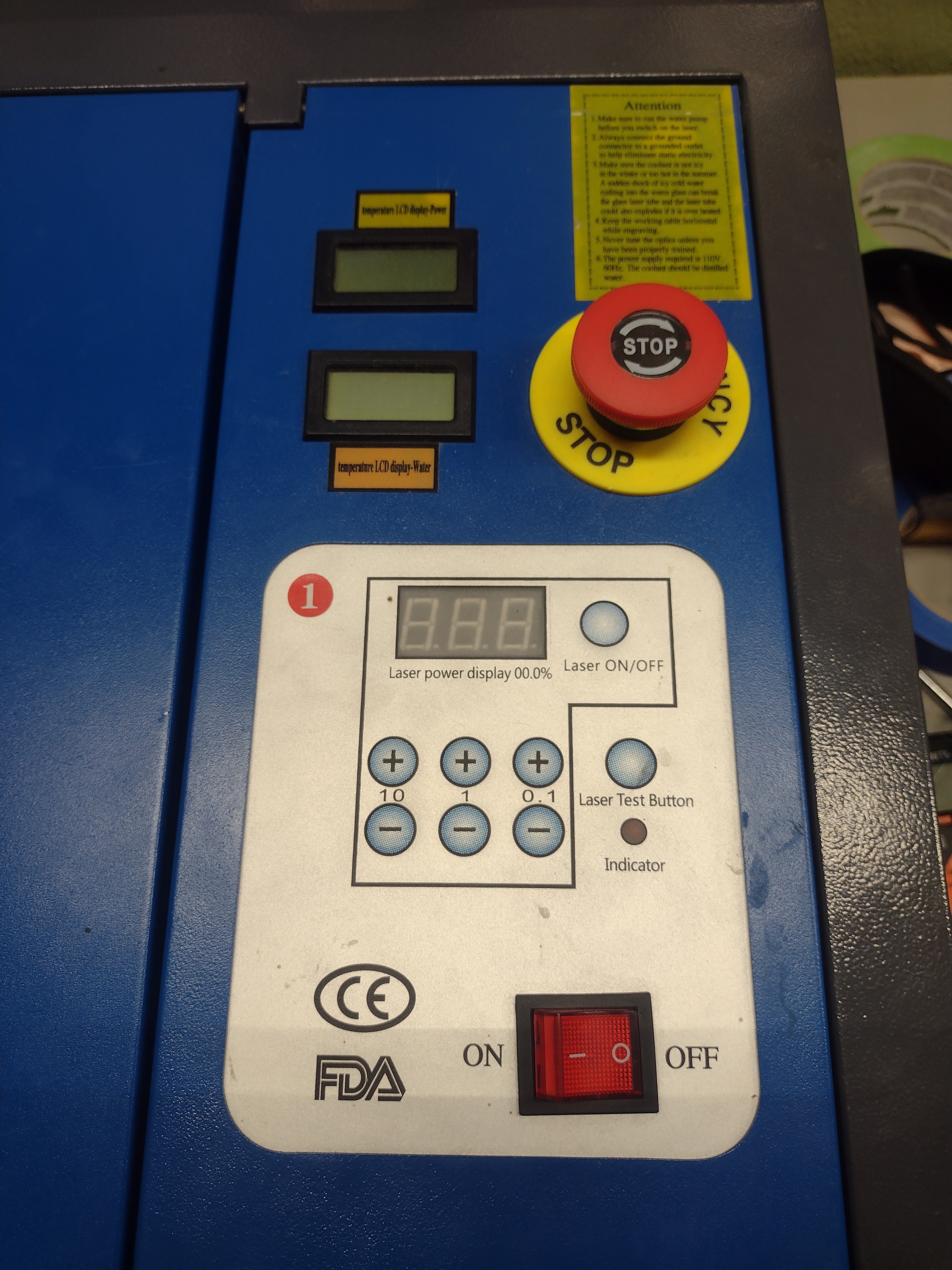
Please post a picture of the panel.
3. Is the laser test switch on the panel stuck on?
4. If you have a “light instruction” Led on that panel is it on continuously? Does it illuminate when you push the button?
This is the current control panel. It is a replacement of the original which had a faulty display. It was the first thing that I replaced when the machine initially stopped working. Though I tried to order a direct replacement, the one I got is not made with a laser test button.
As for the indicator light, I believe it was flashing initially during a raster operation when I installed the new LPS (prior to installing the P+/G jumper), but it doesn’t seem to be illuminating now.
I still have the original which I could reinstall.
No sir. I replaced both the control panel and the LPS while the machine was not working. There is a good chance that the new control panel is doing just what you indicated in your earlier post.
I will swap out the control panel with the original as soon as I have a chance and let you know what happens.
Hi Doug. I misspoke when I said that the new board didn’t have a laser test fire button. What is actually absent is the laser on/off button from the replacement control panel. It is not obvious from the exterior as the labels are just on a flexible layer that does not get removed when the panel is swapped.
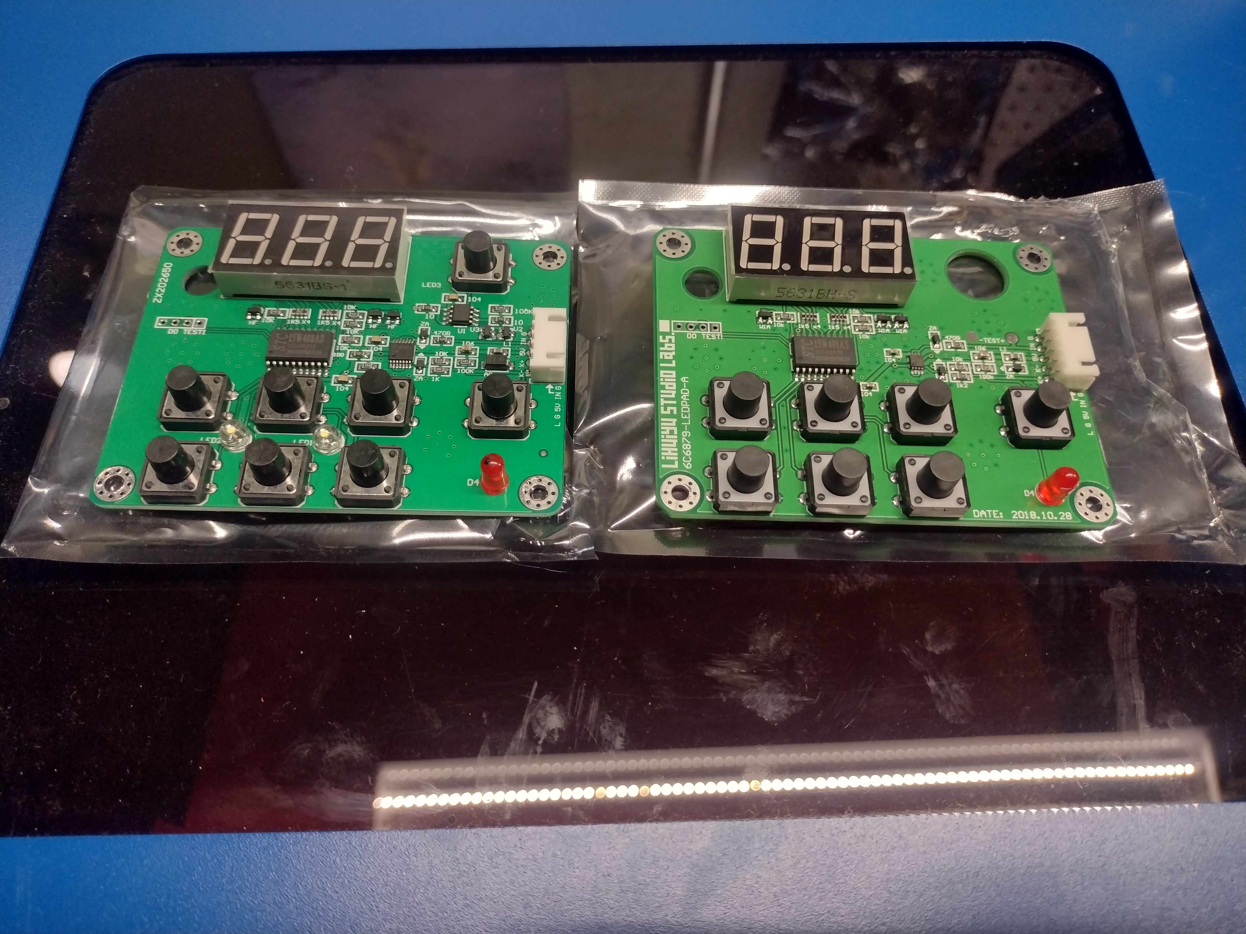
Here’s a photo of the control panel boards side by side:
Next thing is to replace that control panel with a POT and a 30 mA meter… Read the many FAQs out there about K40s and you’ll find many mention how operators over drive their K40s with that panel and kill their laser tube in short order. I can’t emphasis enough reading all aspects of some of these FAQs so you are aware of all the options and issues people have with K40 machines.
The old board is on the left and the new on the right correct?
The new board has a hole where the Laser ON/OFF PB was … whoa!
I am guessing that they replaced the push button on the panel with a switch that is mounted to the panel through that hole. Hopefully, they did not eliminate that function. I wonder how that new switch would be wired into the system.
Maybe someone read my post on how potentially dangerous that panel is if it fails the wrong way… PROBABLY NOT!
This new info suggests to me that the new panel is not worth fixing. You would need to somehow add the laser On/Off switch which would entail drilling a hole and doing some creepy wiring.
I would support thinking about upgrading the panel to an analog meter and pot as @dougl and @mcdanlj suggested. As mentioned there is a lot of info on this site about why to make this change.
Sorry for the late reply. I missed your last post until now.
Original board on left, new on right, correct. In response to mcdanlj, I bought this control panel in a package with another M2 nano board (it does show to ship alongside the M3 board now).
Since we last spoke, I have continued to use the original digital control panel and all has been well with the laser function. I typically don’t exceed 20% setting on the digital panel (as this provides adequate power for cutting most materials with air assist).
I would eventually like to upgrade to the analog meter and pot for power control, and I will follow the Ned Hill guide and the info from your blog when I do so. Thanks to all for the help and advice!
My $0.02 is don’t wait to put the mAmp meter on it because without it you have no idea what kinds of currents you are driving through the laser tube. If you know your way around high voltage and how to use a DMM then you can put that on the system temporarily, determine what display setting gets your your safe max current and then reconnect everything and never go over that setting on the display.