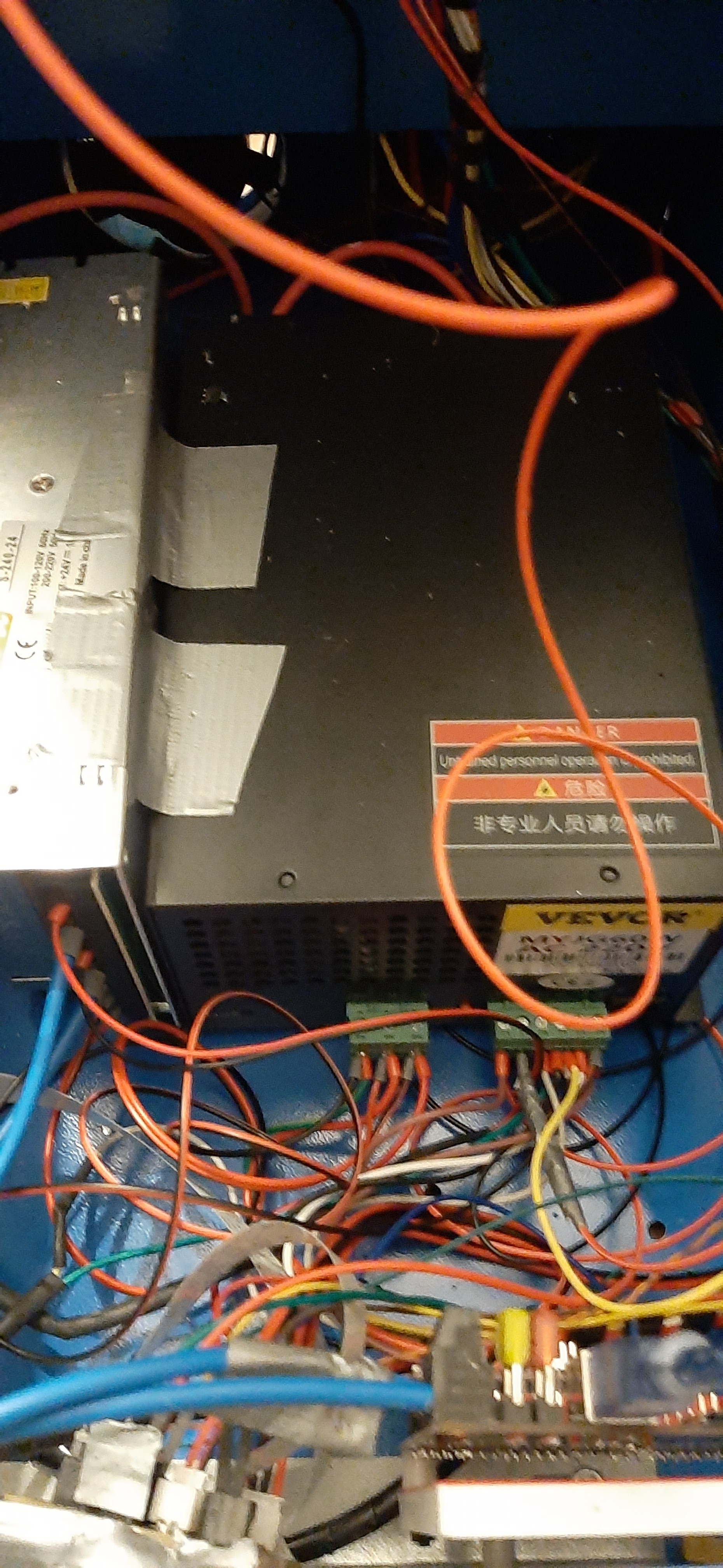
So I’ve completed the setup of my K40 with the SKR 1.4 turbo. Everything seems to be in working order except for a few issues I’m having with PWM.
Setup is as above, 50W laser 60w vevor MYJG60 power supply, SKR 1.4.
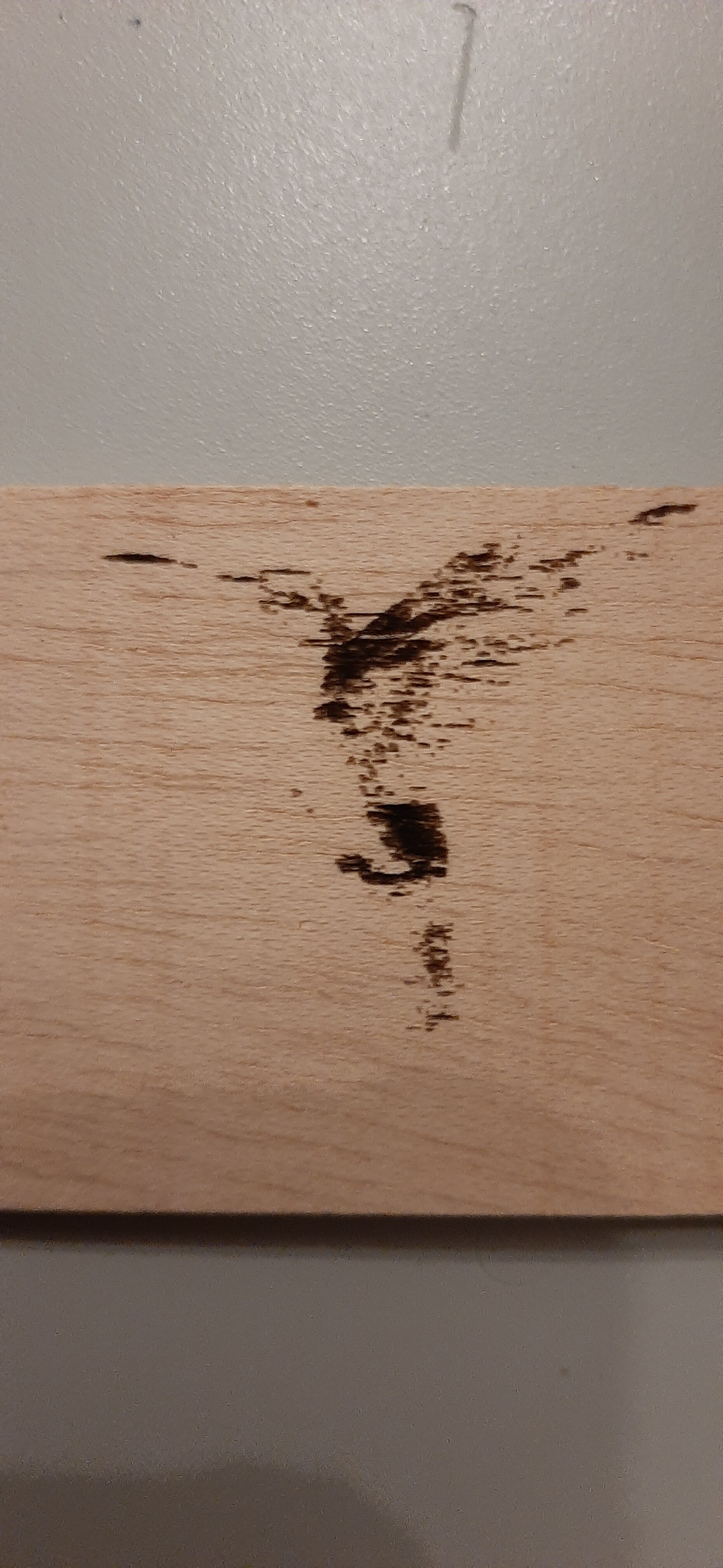
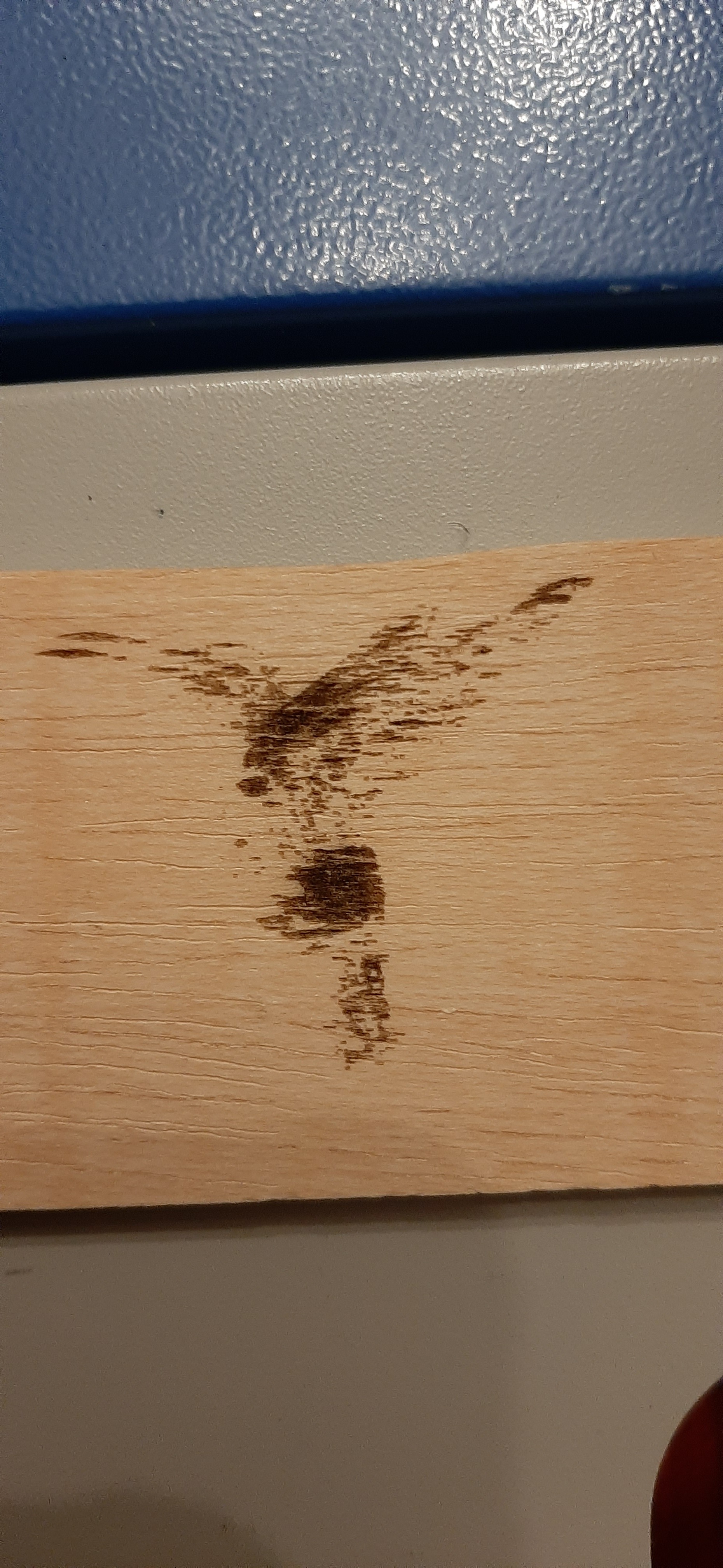
It seems that no matter what I try I cannot get a reliable PWM signal to activate the laser properly so I end up with intermittent images as it seems the laser is not activating, deactivating accordingly.
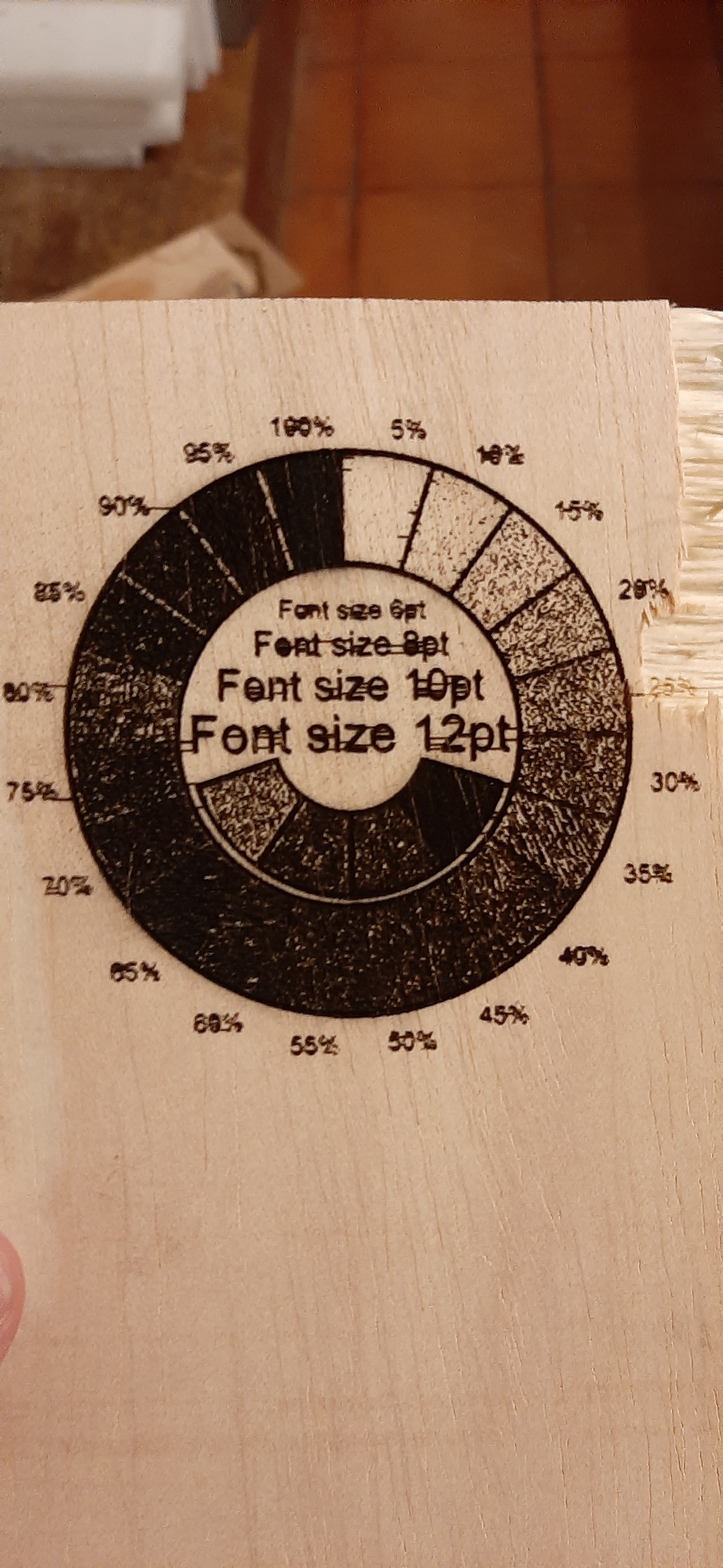
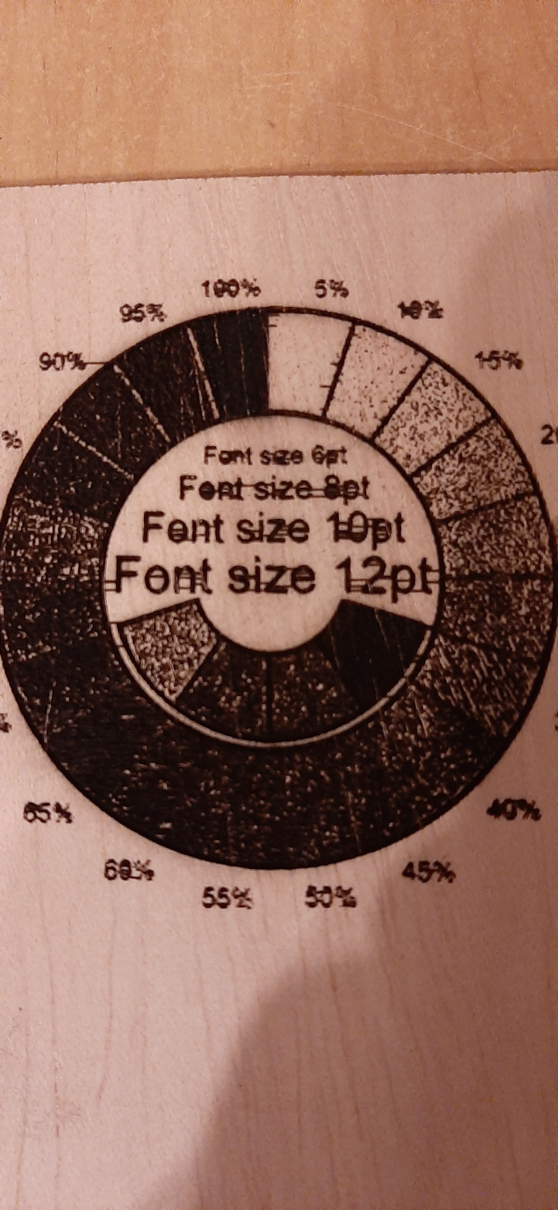
Check images below. The circle gradient was done at 100 mm\s. I kept the PWM setting at 200us, but I tried several options with no luck as can be seen in the birds(no grayscale here) which range from 20 to 400us.
Did you make sure there was a common ground connection between your LPS and the SKR turbo board?
Also, I can’t tell what you wired up but typically you wire the low side of the heatbed or extruder output to the laser control pin on the LPS. You seem to have some control so you probably did that correctly.
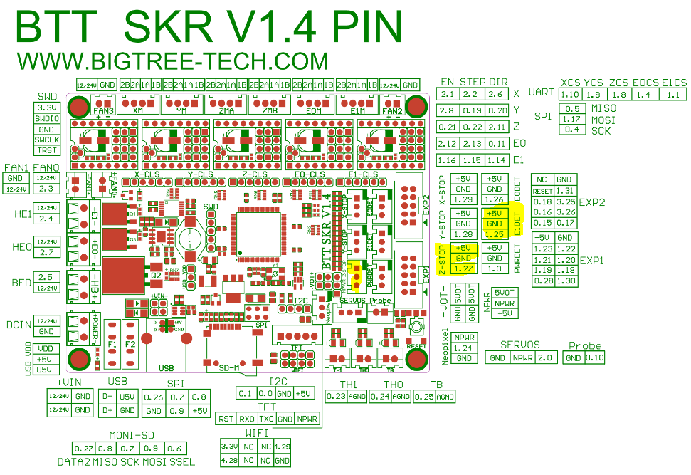
I connected the Servo output 2.0 to the pot in series then to the IN pin of the laser supply. The probe pin 0.10 is currently connected to the power supply pin for turning the laser on on 0V input.
The ground from the LPS is connected to the ground from the SKR 1.4 which is connected to the ground for the 24V power supply which powers the SKR1.4.
The PWM is controlling the power output correctly, as in cuts works fine as it is constant but when it changes this happens. I haven’t been able to connect an oscilloscope yet and it may take some time though.
Interesting way to connect, ie in series with the POT on the IN input. I’ve not tried that or seen it done.
Usual way is to leave the pot and use it to set your max signal level so you don’t over-drive the tube since the stock tube will go fast if driven over 18ma. Then the LPS’s L signal(on connector with 24VDC, 5VDC,GND) is pulsed with PWM off the low side of a heatbed, extruder or fan since the signal is active low.
I’d put an SBase v1.3(32bit) in my K40 years ago and looked at the Cohision3D config file to get the settings right. Cohesion3D, which runs Smoothieware, has been the ‘standard’ for many K40 upgraders since it’s a drop-in replacement for pretty much any K40. Look at their setup and you’ll see it clocks the L signal on the LPS and leave the power level POT in place( on the IN input ).
Smoothieware as well. I think I must rewire it to use your method!
Hopefully that fixes the issues, I was just misdirected by the power supply page which apparently stated I should have used the IN input for the PWM signal.
Well, my tube came broken and they provided a 50w tube as a replacement(which I happily agreed to), and in that case I decided to just buy a new LPS as well since I think the 60w would be a safer bet than running the 50w laser with a 40w power supply.
As for the controller, I just purchased everything together, I never ran the laser with the M2 nano, only noticed the first tube was broken when I finished installing the SKR(my bad).
not much rewiring, just put the 5V/GND across the POT and the wiper to IN. You need a mA(50mA?) on the low side of the tube(between tube and L- on the LPS) to monitor your current.
Then if you google Smoothie K40 you should see a hundred or so pages on setting that up and you’ll see it’s very much like what I said. Did you read the K40 Intro at the top of this page? Lots of good stuff there for K40 noobs. Also http://k40.se is where I got my into to the hacker based K40 laser cutter.
I will read that, I also just found this section in this blog post which also describes some of the problems with this wiring(check The Error section).