(K40 Laser Cut Area Enlargement) High voltage wire and Flyback

Hey All,

I have a question about the high voltage wire and the flyback. I am enlarging the K40s cutting area within the k40s eclosure, so I removed the electronics and its being put in its own enclosure. My problem is two things.

1). The high voltage wire has some chaffing where it comes out of the back of the PSU, due to the aluminum base is real rough.
2). The high voltage wire will now be to short so I bought 6 feet of new high voltage wire with connectors from amazon.

I was originally going to splice in the wire just after the flyback and add the length I’d need, but now with the chaffing, I would like to remove the high voltage wire from the flyback.

Without removing the high voltage wire from the flyback, does anyone know how the wire is connected to the flyback? Is it just placed in and capped, is it soldered, or is it molded in?

Regards
Bill

1 Like

The High Voltage connection is potted into the HVT. I would not recommend removing it.
What supply do you have, show a picture of the problem area?
I thought the standard supply cover does not encapsulate the HV output??
Add a grommet or some plastic grommet material to the edge it is chafing against?

Just add a connector or high voltage splice to the pigtail

Hi Don,

Thanks for the reply. Adding to the pigtail was my original intention, but if It was feasible to remove it from the flyback and start new, that’s was what I’d prefer. The housing does cover it, but when opening and closing the electronics lid on the k40 enclosure, it moves the wire around causing the chaffing. It wont be an issue in the new electronics housing. They probably should have potted it with a 90° bend going to the rear but I’m sure it’s made for a universal fit…

The chaffing doesn’t look as bad at it is in the picture and is where I will do the splice. I would solder, wrap with a few pieces of shrink tubing then slip a section of the silicon water hose over that to prevent arching and any further chaffing. I could easily replace the hose if needed.

Here are a few pictures.

Regards
Bill

I would put this on the edge of the LPS:
https://amzn.to/2Fwn7kq
… and then add the connector to the HV wire making a pigtail as far away from the enclosure as is practical.

… if you make a splice also do it as far away from the enclosure as you can. This voltage can jump up to 2".
If you splice use Permatex Blue RTV and make the tubing diameter as large as you can then fill it with the RTV. Make the tube overlap 1" past any open-wire surface.
When you solder the joint use “Ball Soldering”. You don’t want any sharp points in the soldered joint.

1 Like

Hey Don,

Do you think the length of the high voltage wire will effect the the laser output?

Regards
Bill

Not within reason … like the length of the cabinet.? The big problem with long HV wire is the e-noise & static build up that it may cause. Route it as far away from the electronics as possible.

1 Like

Hi Don,

Thanks again for your reply. I’m using the stock electronics, and both steppers will be on the left side. The laser tube’s + side is on the right, so it made sense to put the electronics housing to the left side of the laser’s enclosure to keep the stepper wires as short as possible and to use the X-axis ribbon cable. The longest wire will be the high voltage, going from left to right, and will be outside and in the back of the lasers enclosure. I was going to encase the high voltage wire in a silicon water tubing.

Regards
Bill

1 Like

Hey All,

I started tearing down the laser and repopulating the electronics in a new electronics enclosure.

There is no way to splice the high voltage wire to where it’s not going to be anywhere near the metal enclosure. It’s just too short from the factory. Either I have to splice it, and it will be next to the metal, or I remove it off the laser tube and reconnect it back onto the laser tube with a longer piece from the 2-meter selection I have. If I do that, I can then can splice it well away from any metal. I can reconnect it back onto the laser tube just as it came from the factory with silicon and a water tub section filled with silicon that came with the laser.

Any thoughts?

Regards
Bill


I think either will work as long as you make the splices correctly including the tube connection.
If you have a long enough piece, I would elect to use the single piece and make the connection at the tube.
Is the LPS staying in the laser cabinet or the electronics cabinet?

Hi Don,

Yes, all the original electronics are to be used and enclose in a separate box. Here are some pictures. I need to shorten the wires and connect them to the PSU. I placed the top on to give you an idea of what it will look like. I am amazed that the color the box comes in matches the K40 enclosure, and the three covers almost perfectly. The open rectangle hole in the front is were my digital water temperature gauge goes. I haven’t gotten to that point yet.

Regards
Bill

Is your HV cable exiting the electronics box and then entering the box with the laser?
I would be nervous about that being outside where a human can access it.
You know that that cable runs 20,000v right?
If it runs outside I would fin a way to enclose it …

I strongly urge you to add interlocks to both sets of covers, the electronics, and the laser compartment.
You also should include water flow and water temp sensor into that interlock circuit.

1 Like

Hi Don,

Yes, the HV cable will leave the electronics box and run behind the laser along the wall. It will be 100% enclosed within a silicon hose the same kind as they put on the laser tube connection points. There is no possible way it can be accessed unless you move the laser enclosure. A few things left to do, like shim the head, drill and mount #1 mirror, lengthen the stepper motor wires, mount the limit switches, connect the HV wire, and splice the - (neg) wire to the tube. Also, add a ground wire connecting the electronics housing to the laser housing, cover some of the openings in the back of the laser enclosure, adjust the tube alignment, and then fire it up to align the mirrors. I have all new mirror mounts and head, along with mirrors and a new lens.

I’m almost at the end of the tunnel.

2 Likes

Once you get this built I would test the shielding on the HV cable.
Lay a ground wire next to the tube and pulse the laser in the dark to see if you get leaks.

I don’t see interlocks on your list of to-do’s :frowning:

Hi Don,

Yes, I was planning on testing the HV line, but I’m not adding any interlock switches. I need to get inside and test-fire the laser to align my wood when cutting. I make laser-cut balsa wood airplane kits, and not all the sheets are the same size, and they get spread out, so I need to align them individually using my targeting lasers. The sheets are jam-packed with parts, and most of the time, I trim off .032" or less of the overall size. Balsa wood is far too expensive to do it any other way. I have laser safety goggles that I store on the lid, so there is no getting into the laser without putting them on.

I have a question about the limit switches. I am ditching the ribbon cable and optical limit switches and am using mechanical micro switches, as shown in the picture. I have two on the Y-axis, front and back, and one on the X-axis on the left side. I am also using the stock M2 Nano board with K40Whisperer and testing Meerk40T software. I want to plug in the X and Y-axis steppers into their respective plugs and use the 5-pin connector to limit switches, as shown in the M2 Nano board picture. I think I understand the 5-pin connection to the board for the steppers, but I am wondering If I leave the 5v at the top of the plug labeled NC alone?

Also, would the micro switches’ connections be in the open or closed position, as shown in the switch drawing?

I have included a picture of one of the switches I am using.

I have six different colors of 22g stranded silicone wire for the steppers coming in tomorrow to extend the stepper motor wires, and I already have 50’ of 26g 3-wire for the switches. I’ll peel one wire off.

Oh, I almost forgot, what is the voltage of plug #5 in the picture of the M2 Nano board?

Regards
Bill

Seriously @Bill-CNC, there is no project that is more expensive or more precious than your sight.

No matter what you read on forums about folks using laser glasses as a safety excuse for not adding a few $ in interlocks, glasses are not intended to be the first line of safety for any laser system. Enclosures and their interlocks are.

Laser accidents happen because mistakes happen. If you make a misteak with this laser, you will not have a second chance… you will lose your sight. Your eyesight cannot be recovered from laser exposure, you will be blind!

BTW: Laser and electric safety are not just put in place to protect you they also protect anyone in or near the environment.

You should consider that your creativity in packaging has also created additional safety hazards:

  • The controller is separate from the engraver meaning that a laser or electrical accident can be initiated both at the control cabinet and the engraving cabinet.

  • The laser HV supply runs outside the cabinet. That means that if the jacket arcs ** to a nearby conductor it will lite up that surface and anyone and anything touching it or within 1-2". HV wires are run inside a conductive and grounded cabinet so that if an arc occurs it has a solid pathway to ground that is not via a human. A nearby conductor can be anything conductive enough including, table surfaces, cabinets, tools, jewelry.
    If you get connected to this LPS in the right conditions YOU WILL BE ELECTROCUTED.

BTW at this voltage materials have surprising conductive characteristics. Things you think are insulators may not always act that way.

**I am not convinced that silicon tubing has the dielectric strength needed to prevent a 20,000v arc. In addition materials under this high of dielectric stress can break down over time and eventually arc.

@Bill-CNC I urge you to find a creative way to make your system safe and also meet the needs of your hobby.
I would make suggestions but I don’t understand the nuances and what is unique about your cutting process that it prevents interlocks…


As far as your question(s) on the Nano wiring I do not use a nano, my system uses a smoothie and middleman board with the ribbon cable and optical sensors.
I suggest contacting the Meerk40T guys for the pin connections and polarities. I think the hardware guy over there [sorry don’t know his name :(] has interface information.

If you cannot get answers there let me know, as I am sure I can figure out the answers.

2 Likes

Hi Don,

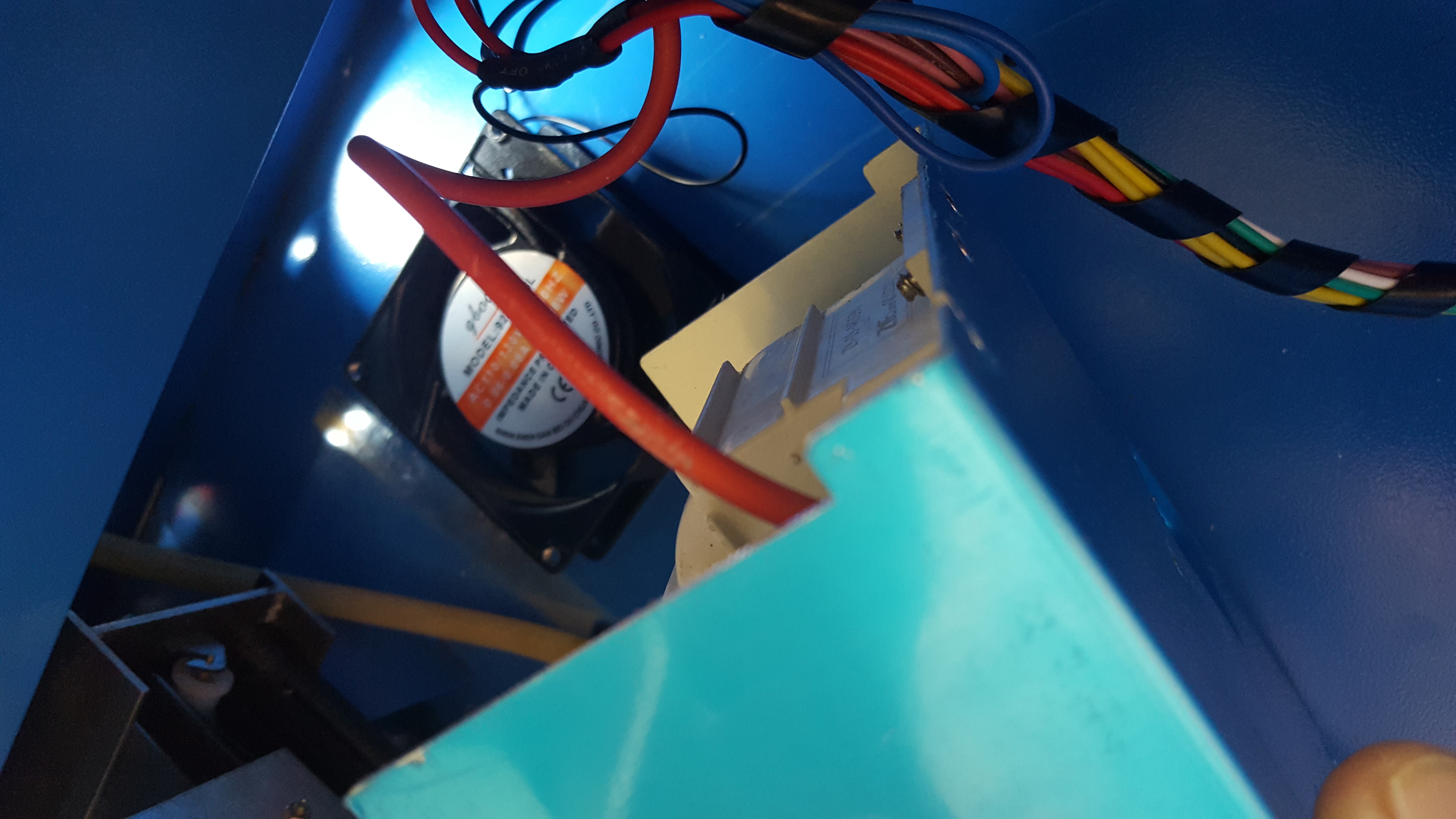
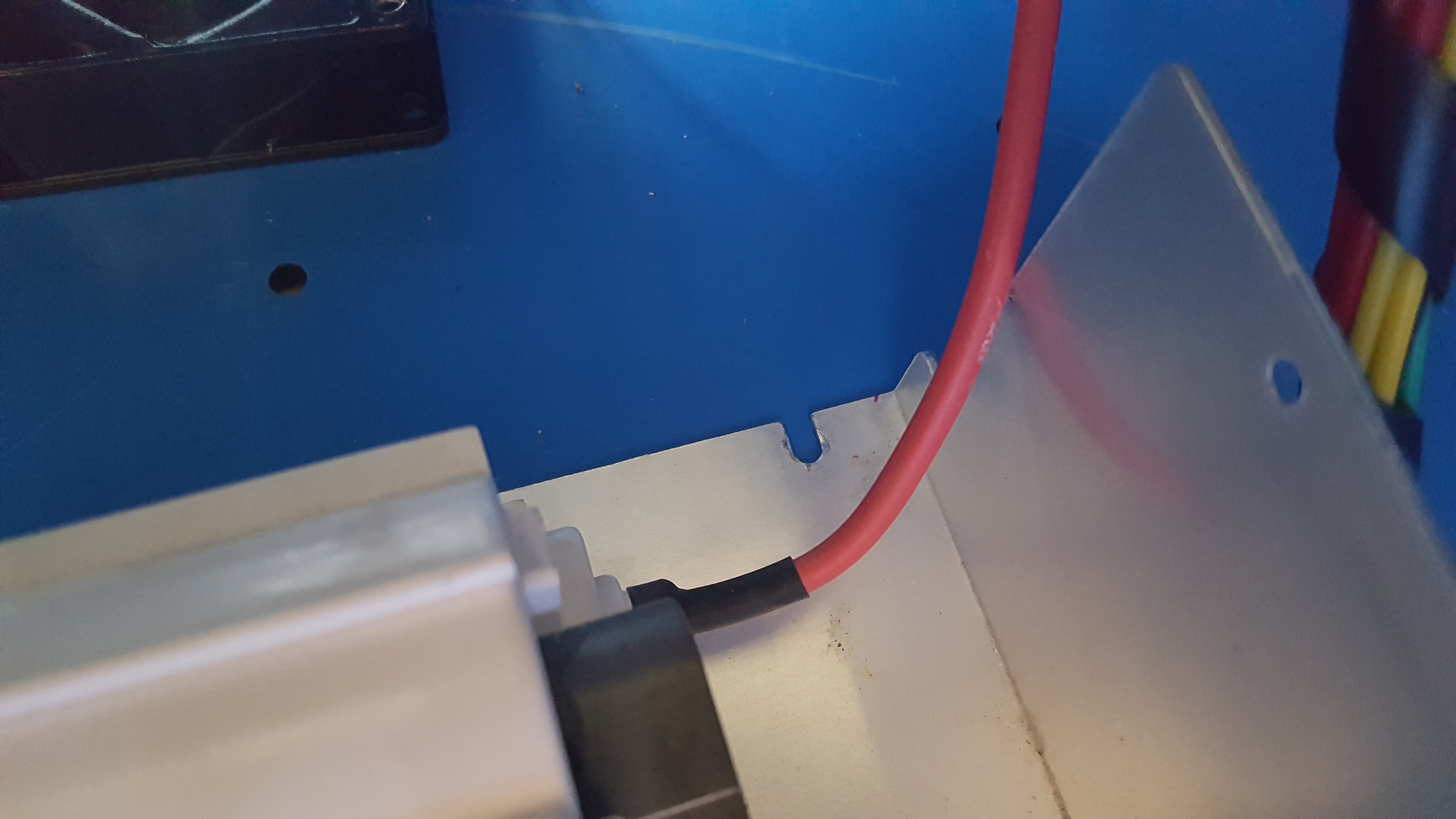
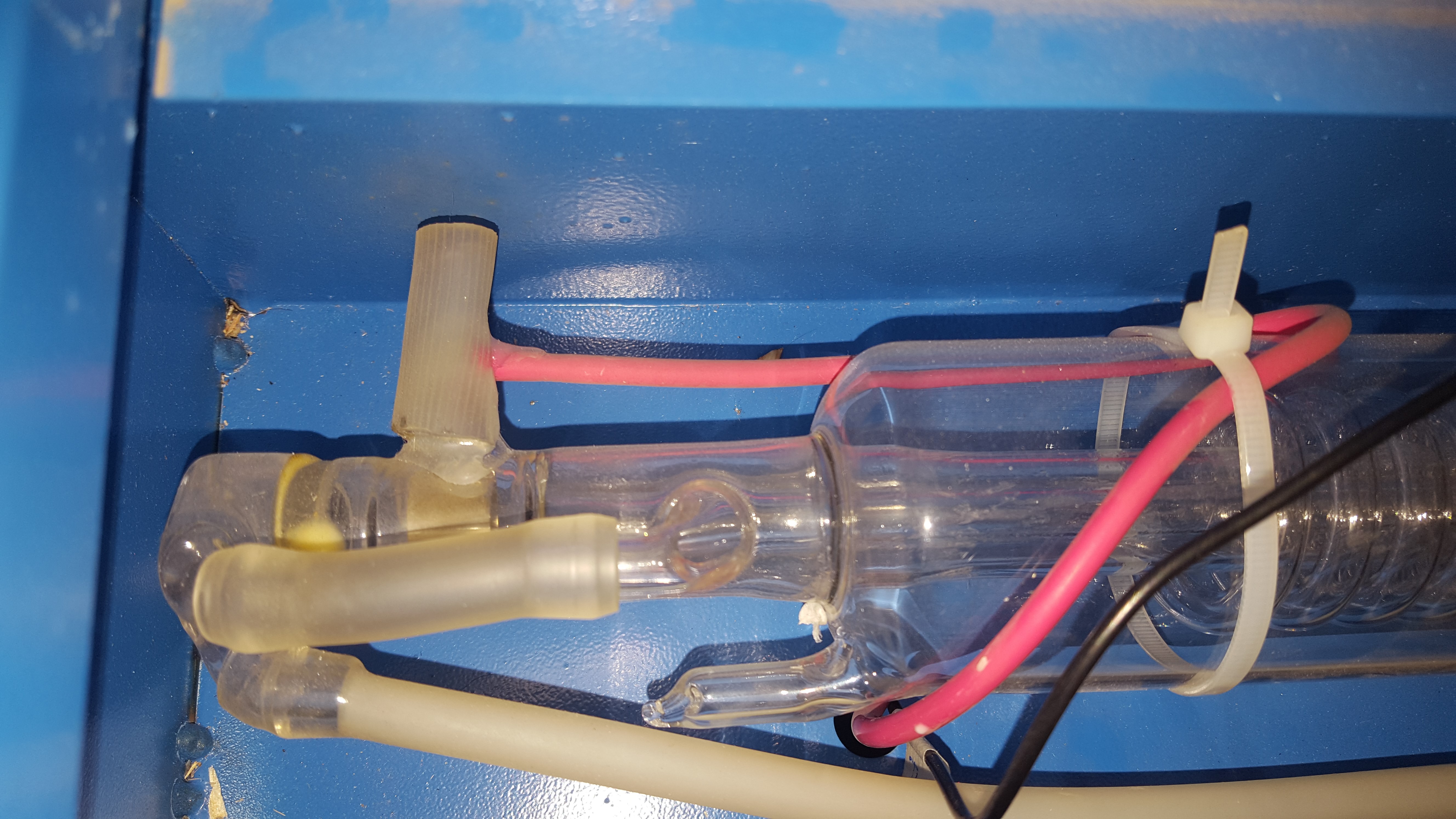
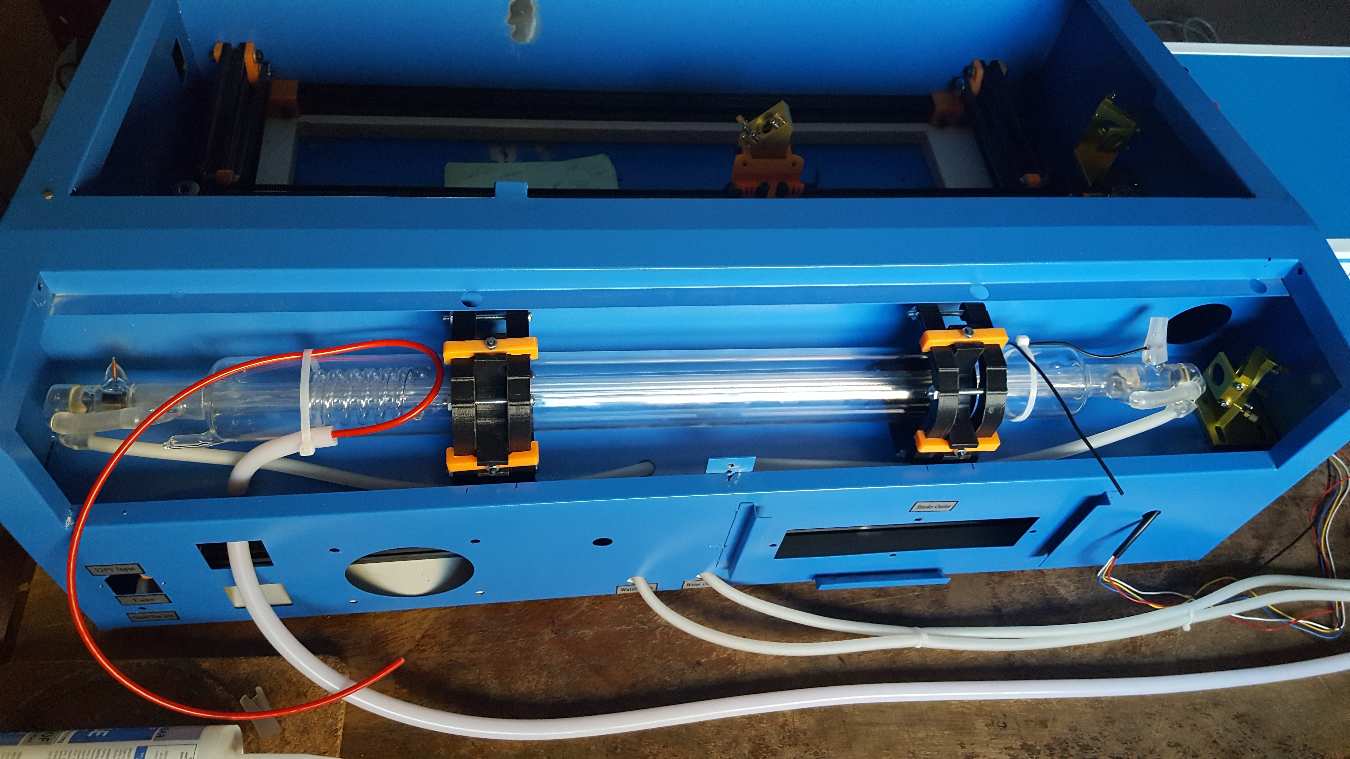
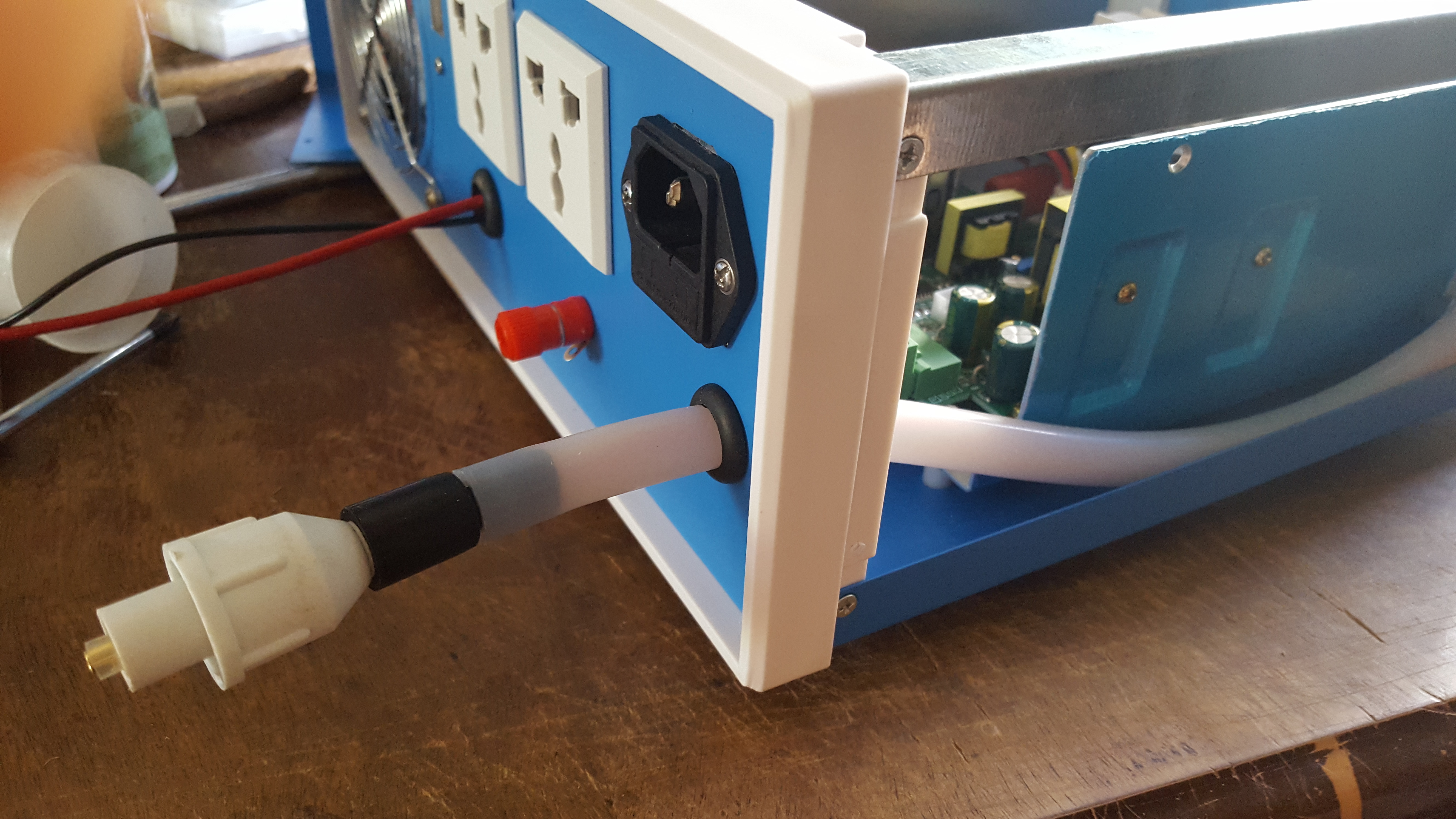
I understand your concerns, and I do thank you for them. I followed this video from the lightobject for wiring the tube. They explain the silicon tubing for the HV wire.

As for the lid switches, I only test fire to find the corners of my piece to get it aligned for cutting. As I mentioned before, I only cut off the outside edge of 1/32" or less, so the sheet’s alignment is critical. ALL cutting and engraving are done with the lid closed.

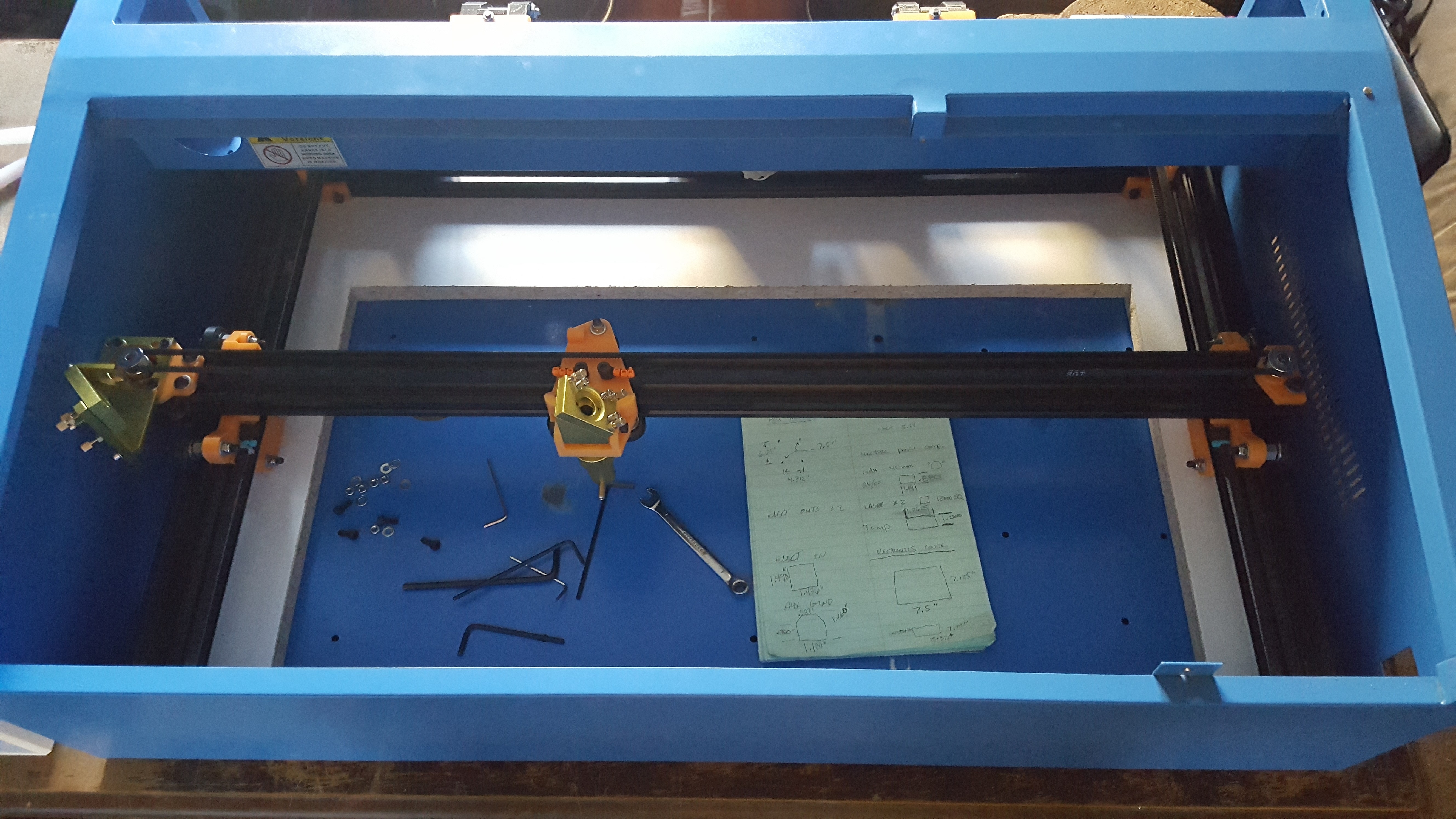
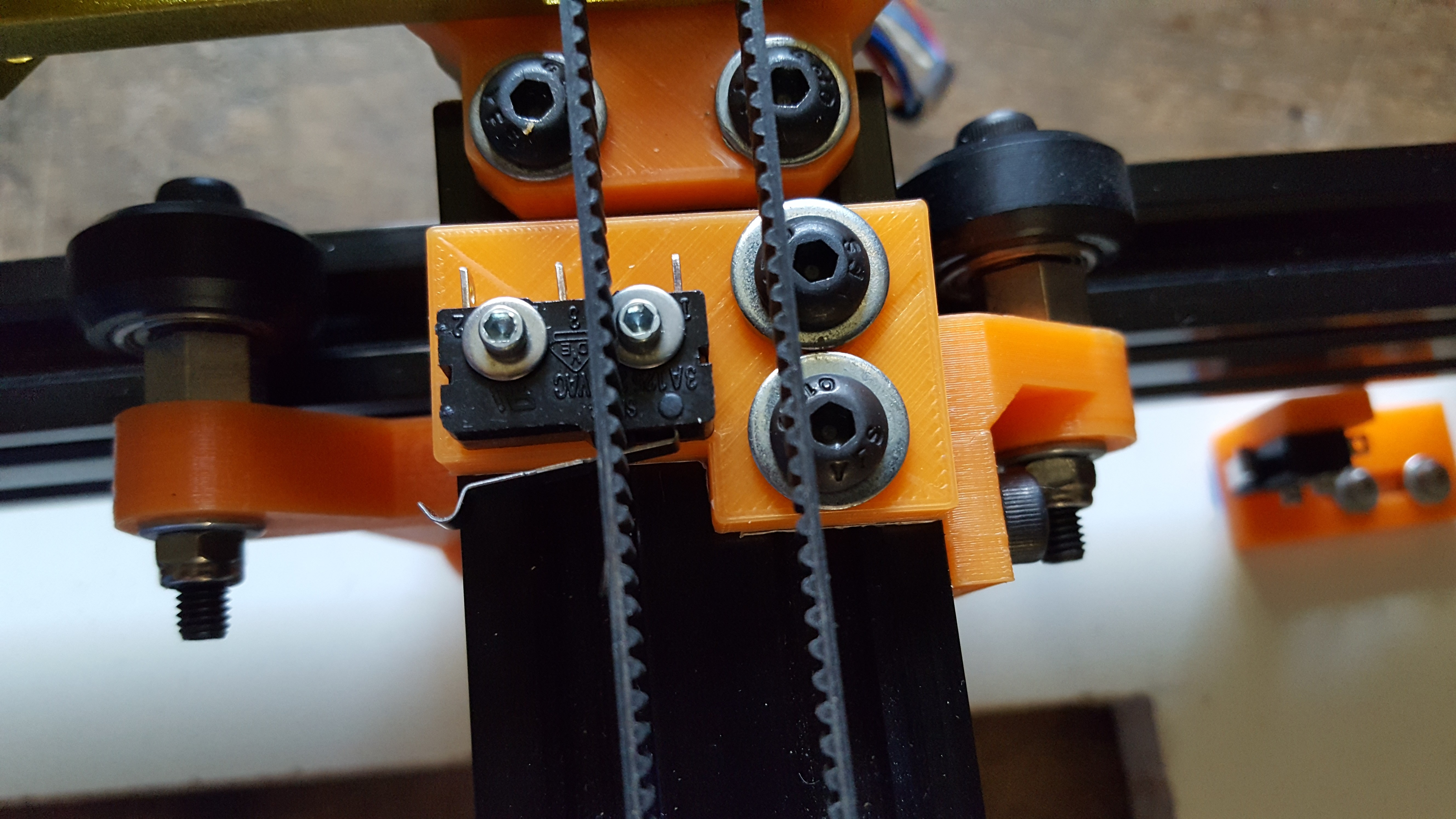
I’m happy to report that the laser is once again alive. The mechanics work perfectly, but I could tighten the X-axis belt a little bit.

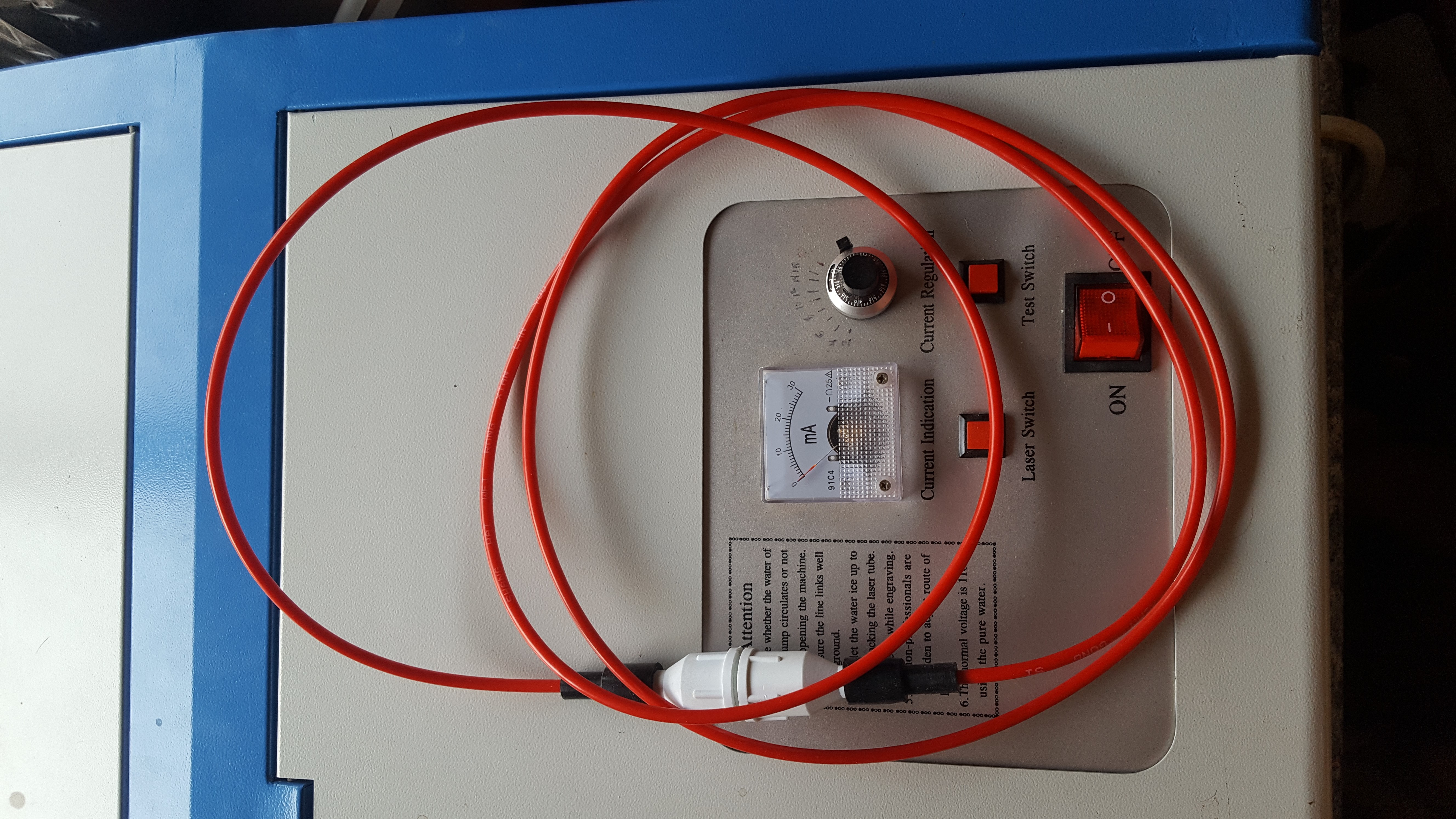
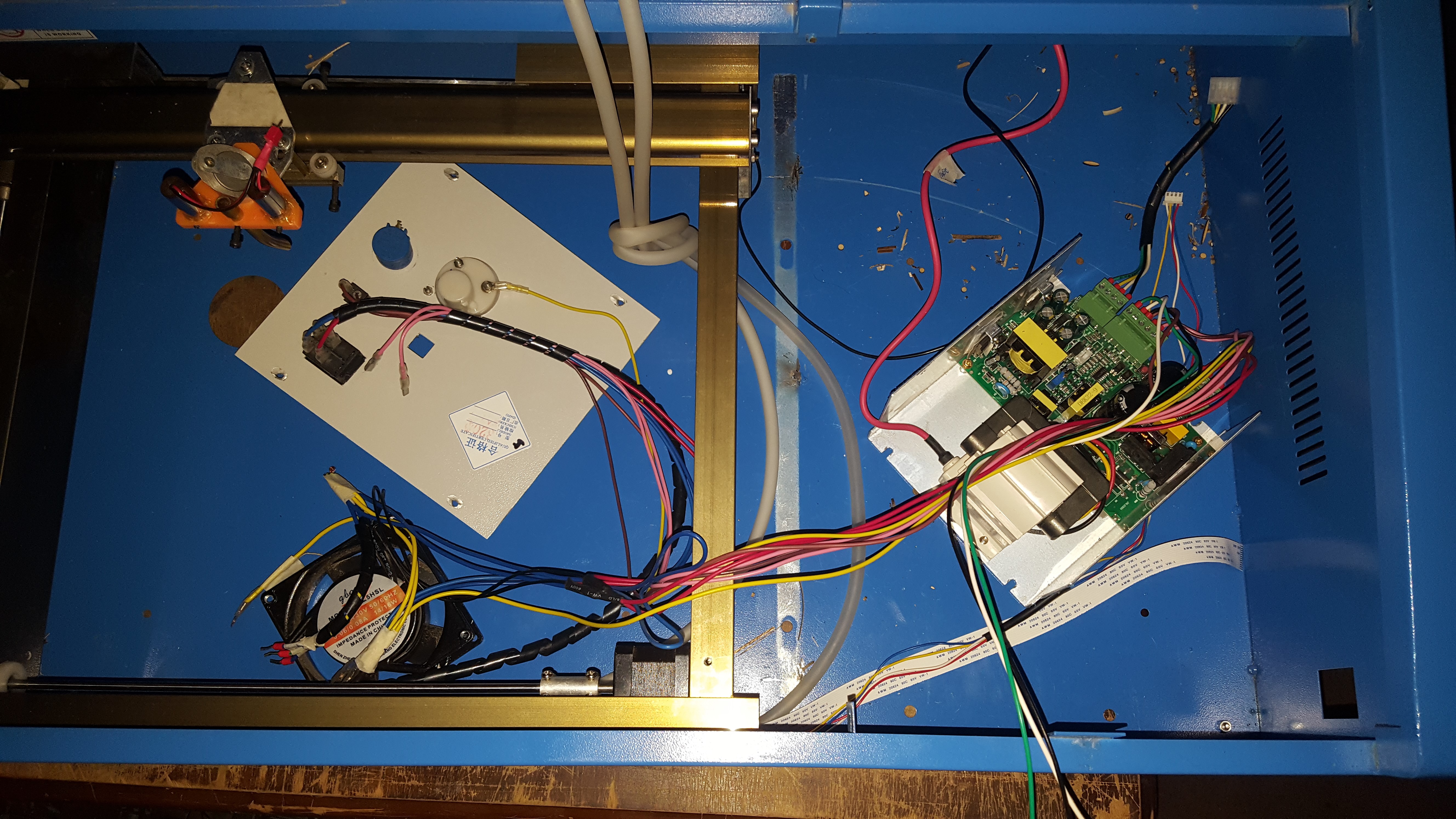
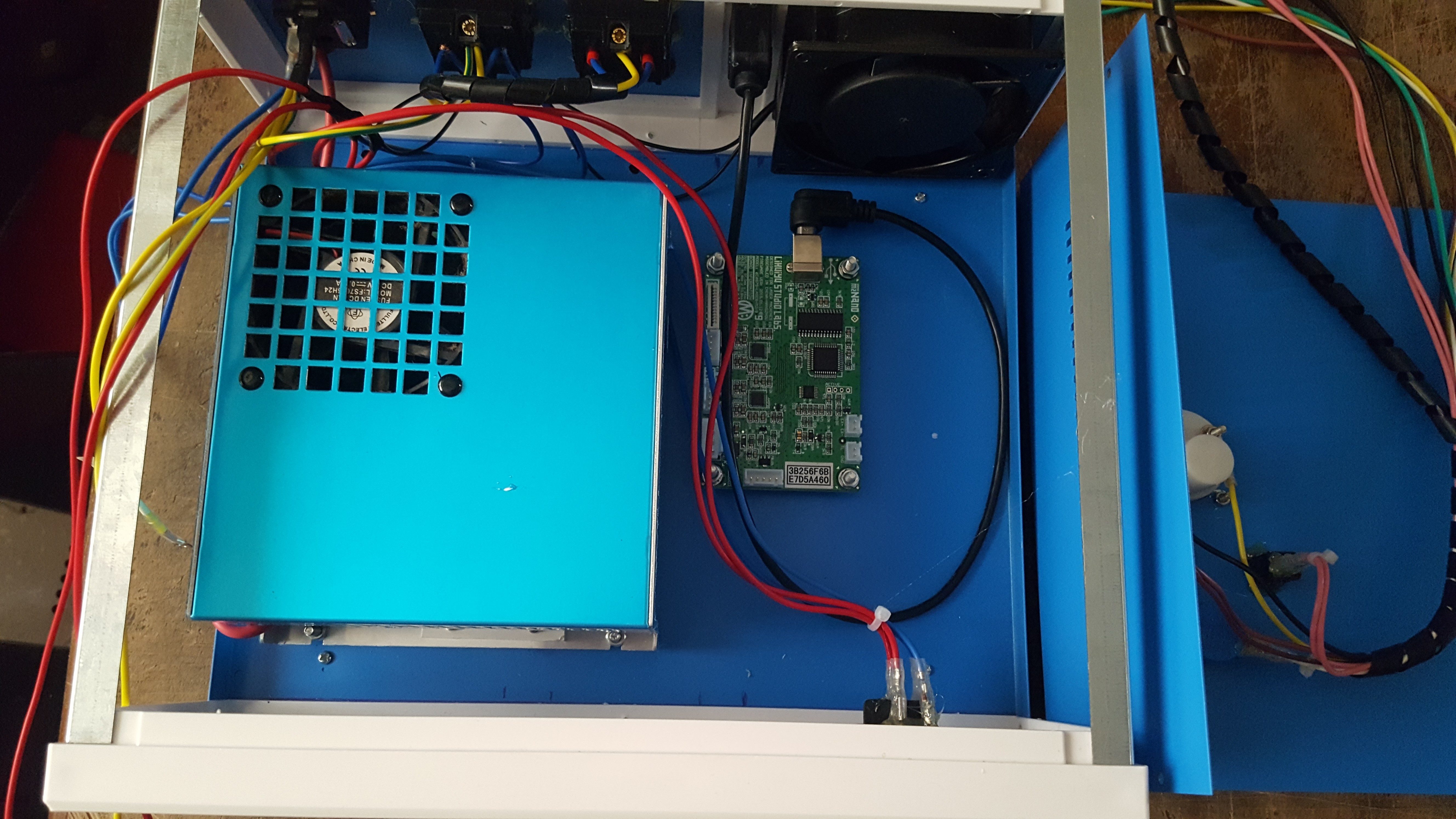
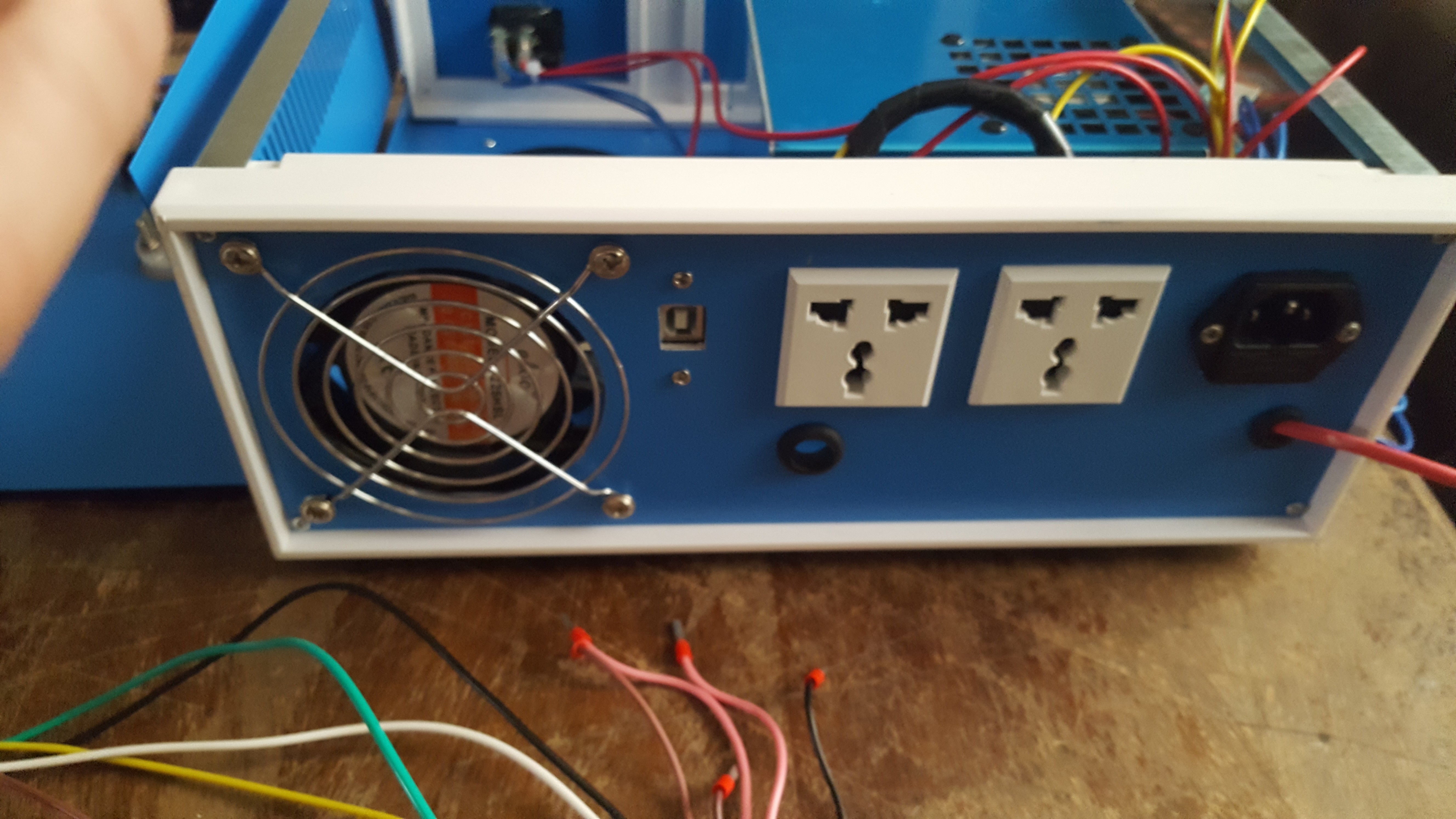
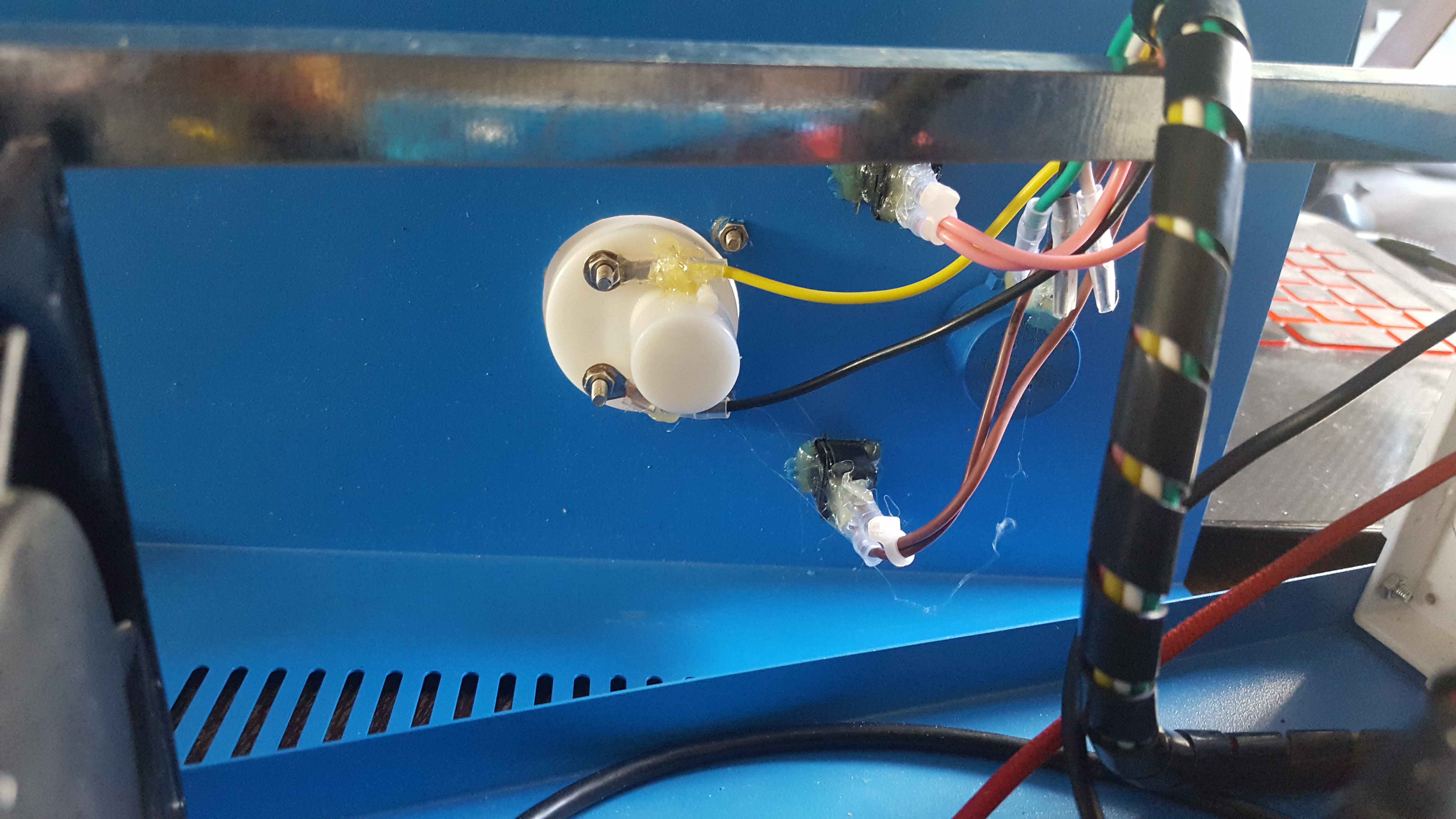
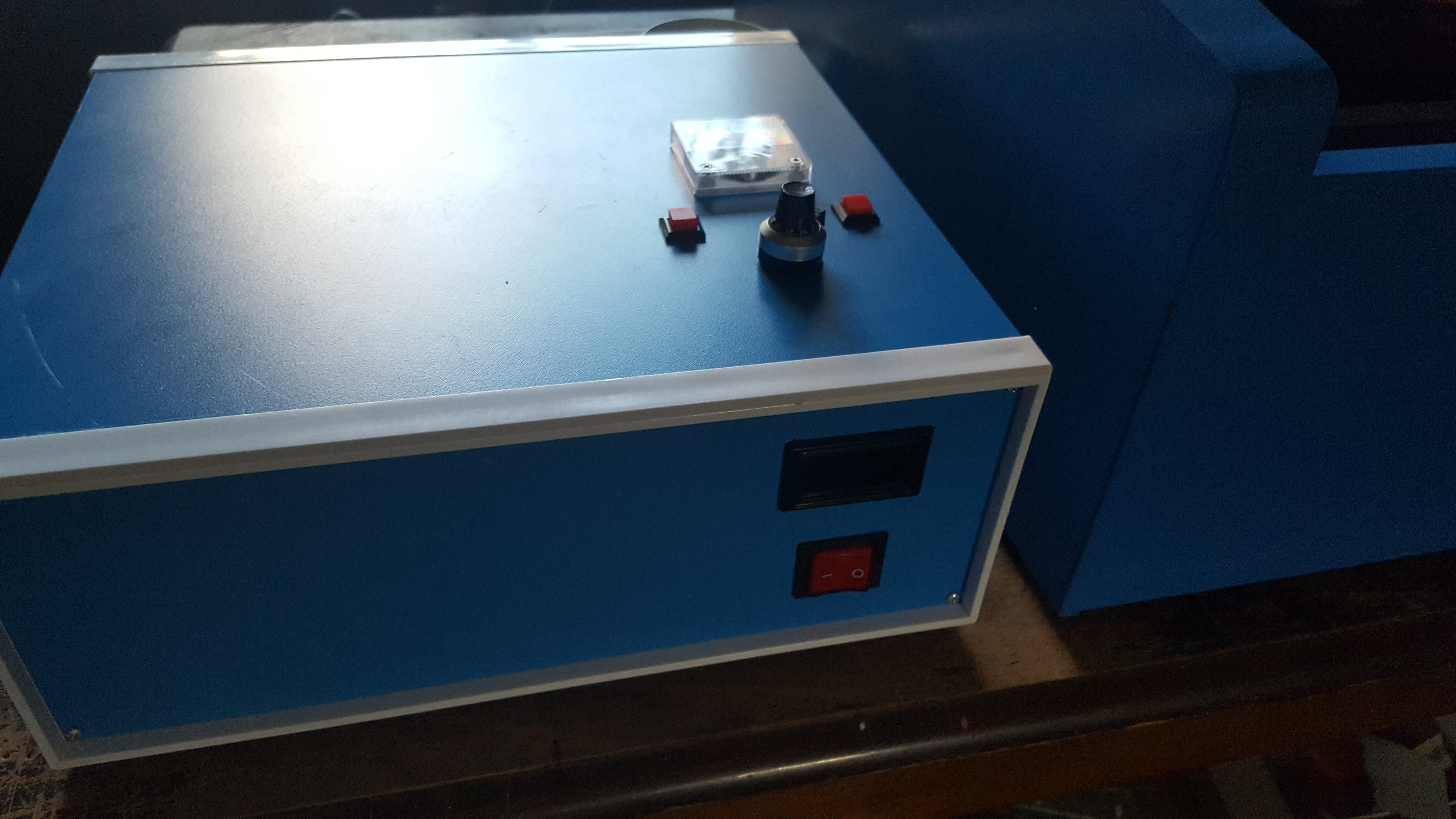
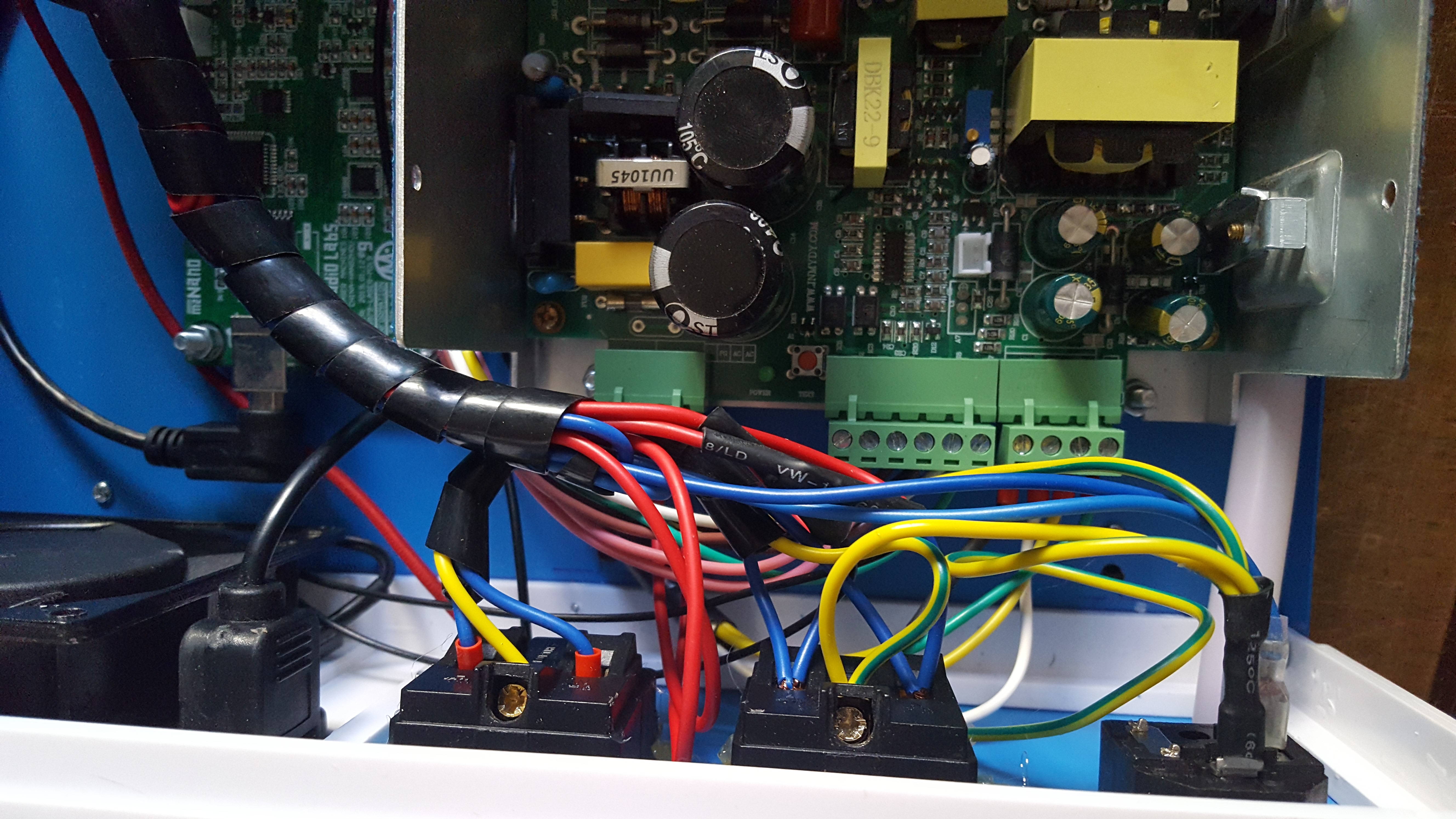
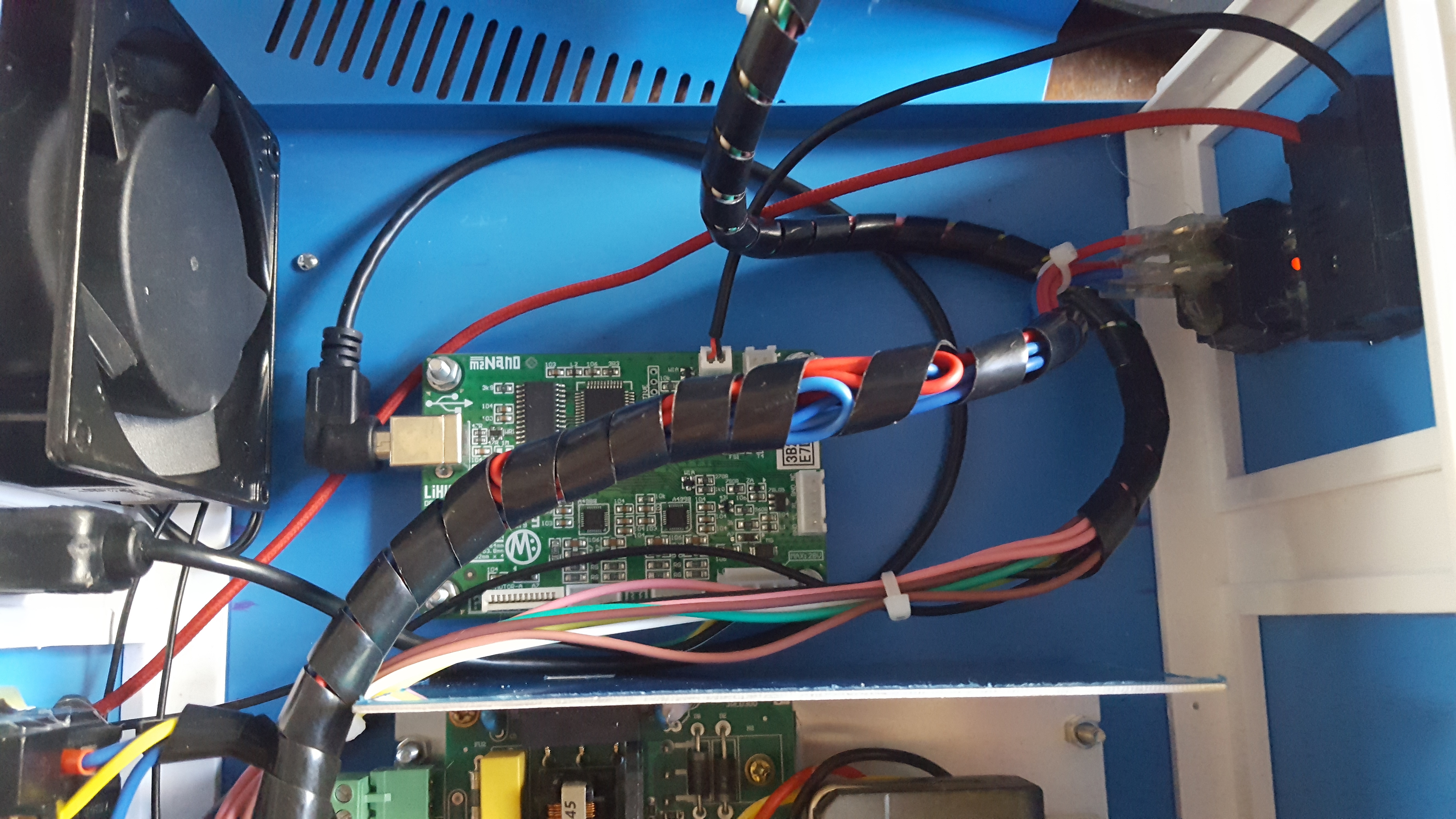
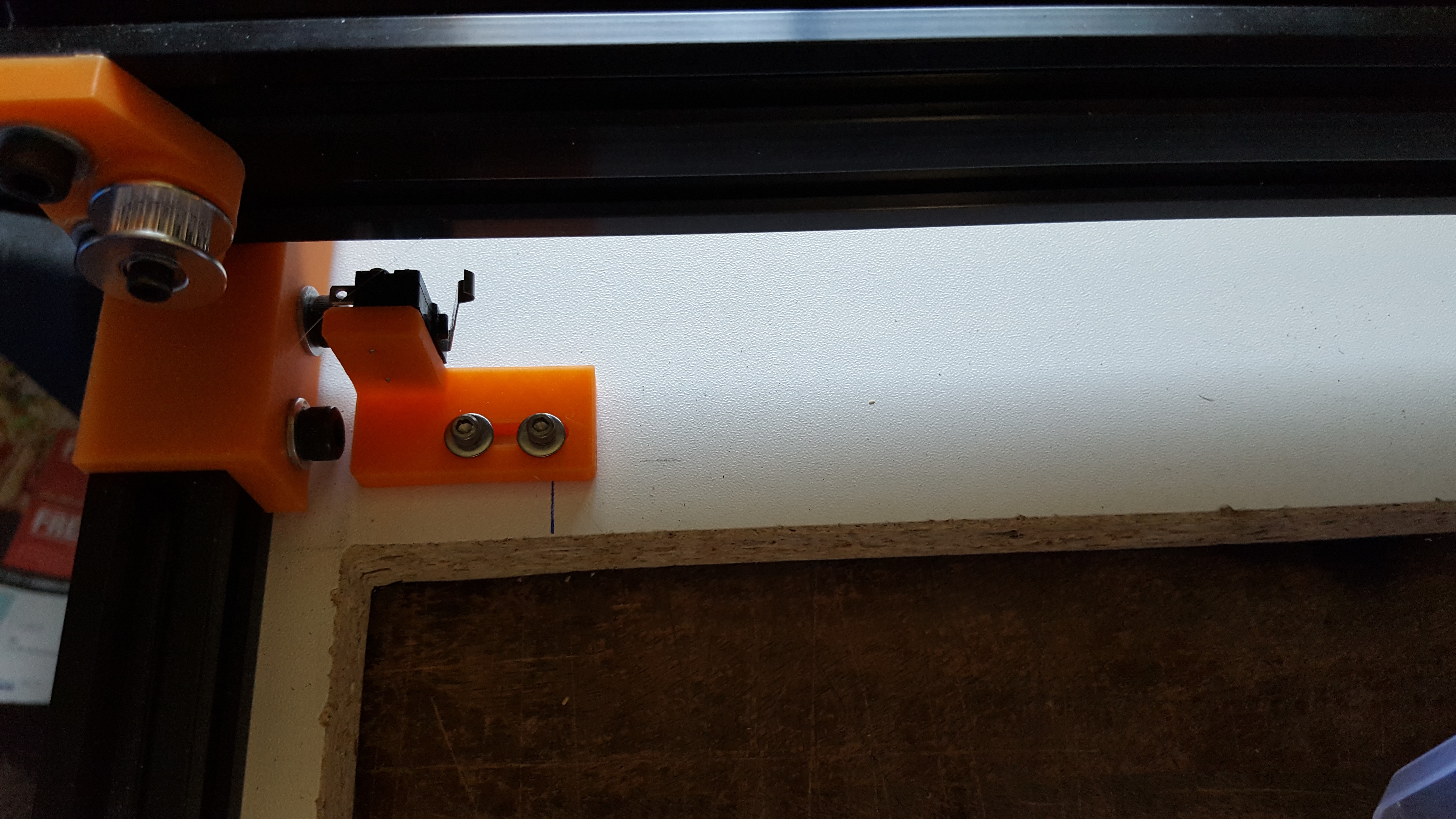
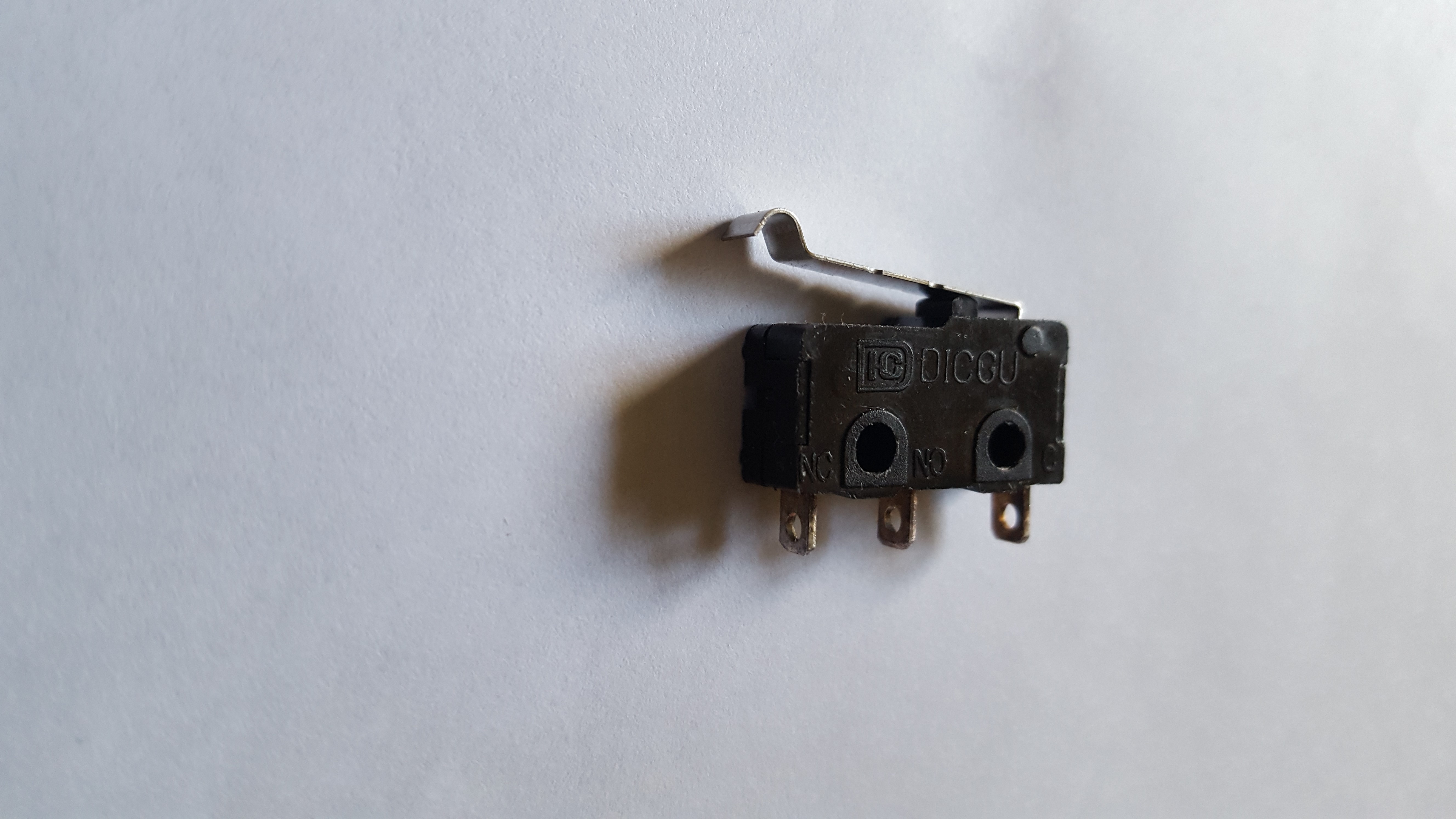
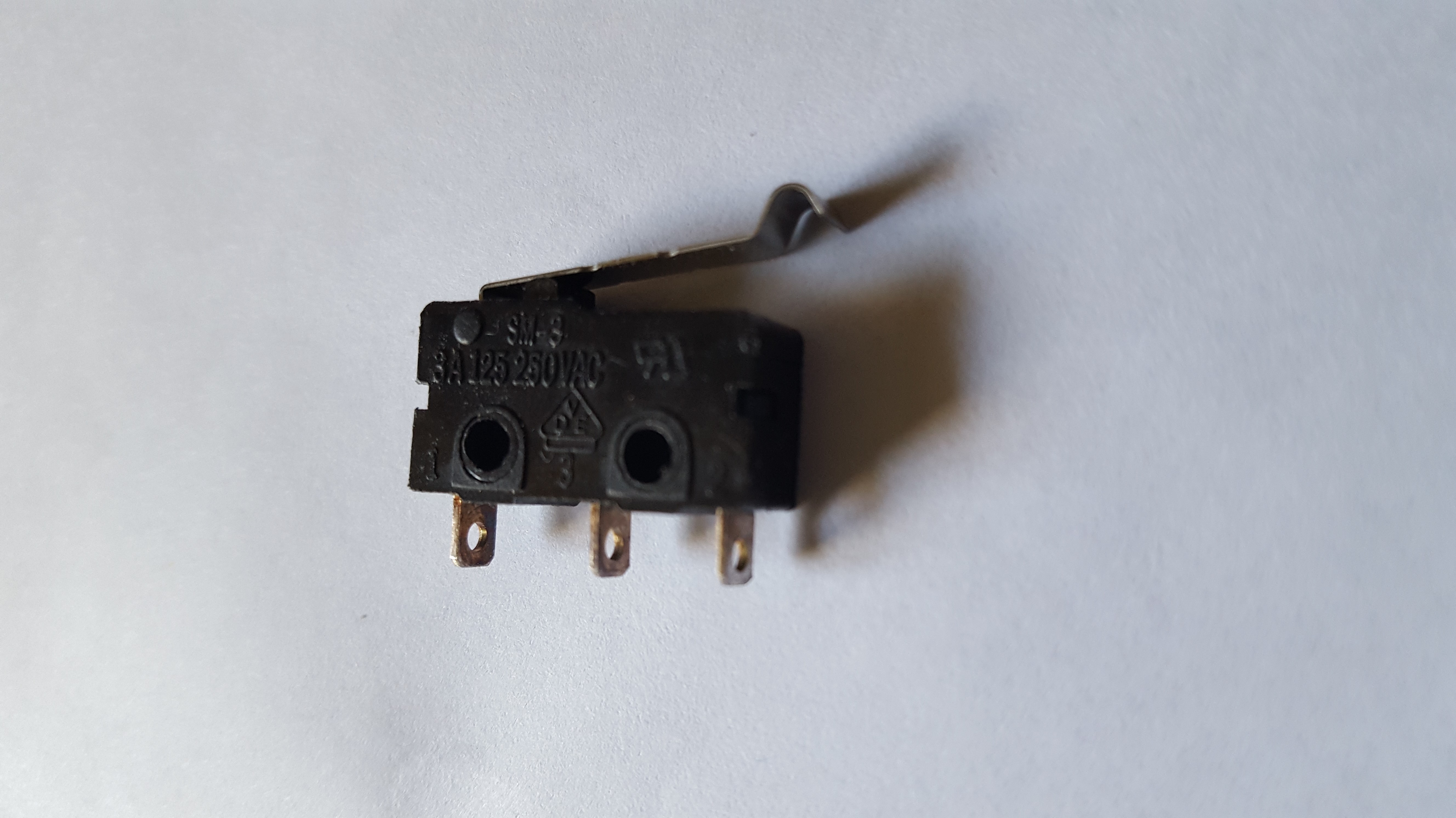
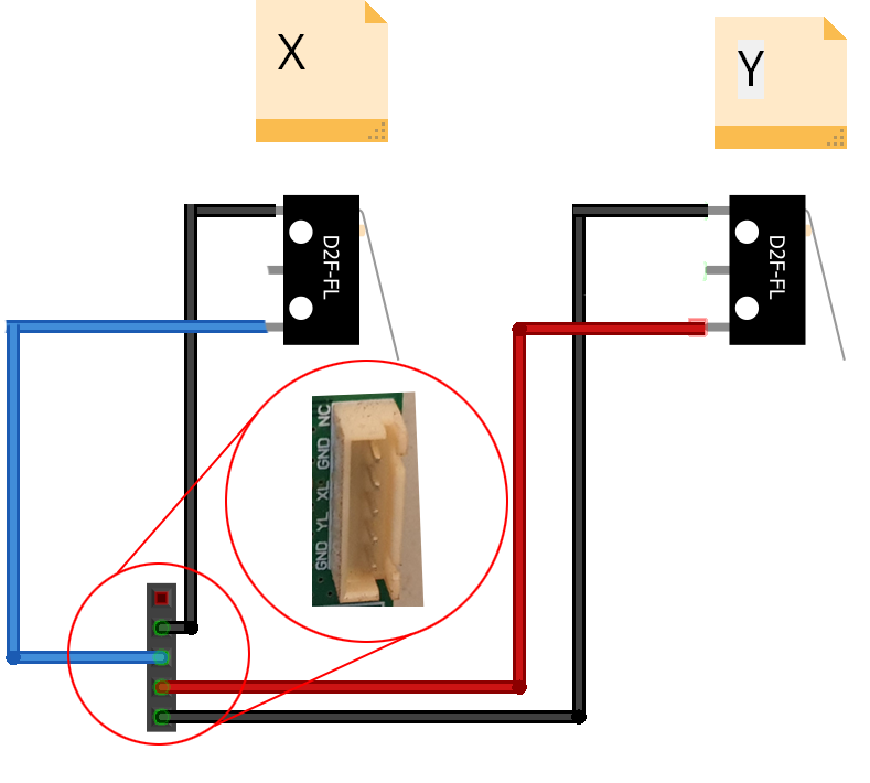
I ditched the ribbon cable along with its optical switches and daughter boards on the electrical side. I added four limit switches, one at each end of both the Y and X-axis, and they work great. They are wired straight into the 5-pin plug, as shown in the picture I previously posted. My only issue with the wiring is that when plugged in, the power switch is always glowing even when powered off. I need to switch the red common and line wires on the button, which should solve that.

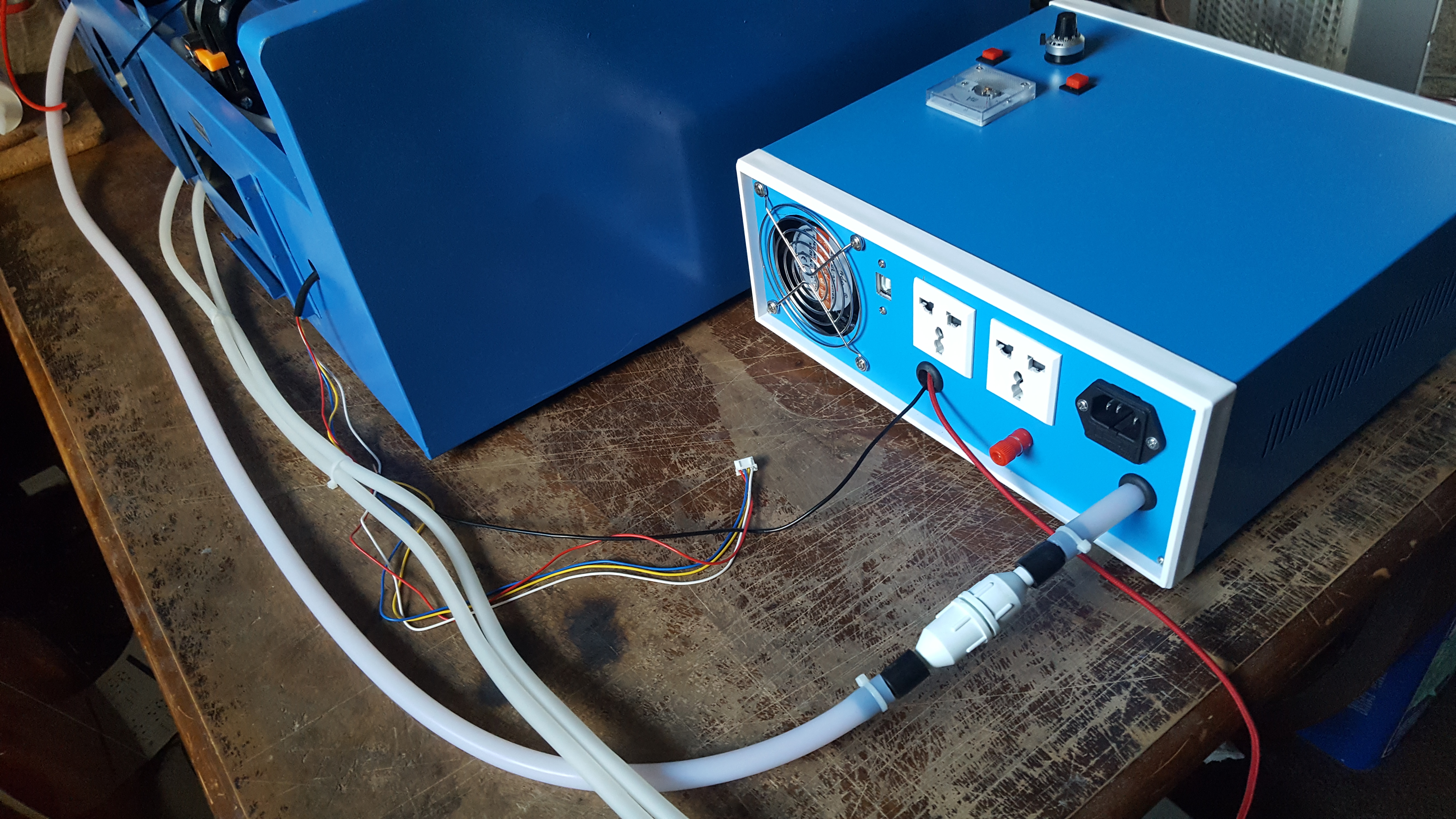
The laser tube works perfectly, and there is no arching anywhere in the circuit. Right now, I am currently aligning the mirrors. It takes a little more time than a stock K40 due to being a little larger, and it’s a bit tighter to work on the 1st and 2nd mirrors. I probably should have bought the alignment tool from American Photonics for simplicity, but I’m a patient guy with time on his hands.

My actual movement came out to be:
X-axis 607.009mm (23.898")
Y-axis - 260mm (10.236")

Here is a couple of videos showing the first homing from the heads farthest position, and one of it simulating etching. There is a little vibration in the X-axis due to the belt being a little loose.

Homing testing the limit switches

Engraving movement test

Once I get the mirrors aligned, I’ll post a video of the machine at work.

Regards
Bill

3 Likes

Ok just keep in mind that the lightobject video is not intended for external wiring.

Hi, very nice project u got there @Bill-CNC.

So from what I understand your max workable area became:

X-axis 607.009mm (23.898")
Y-axis - 260mm (10.236")

By moving the control module and power supply outside the original enclosure.

Very nice indeed.

Also - did u have options for ready made rails in that size or going custom was your only way? At least seems like u used some 3d printed or otherwise custom made brackets/holders of some parts…

Yes, … the project went very well. It is controlled with a Raspberry Pi 4, 8 GB, and has a motorized Z-bed controlled with Arduino Uno with a CNC Shield for controlling the Z-axis only.

Regards
Bill

3 Likes

Hi Bill,

First off, thank you for all of your contributions via the forums, youtube, etc. You’ve really helped me in my quest to revamp my K40 with my very limited knowledge.

I’ve printed the entire set from your YouTube series and am. Awaiting some parts to complete my project. Recently though, I saw where you’ve switched to a x axis sled that uses 4 wheels instead of the three wheel version that I printed. Can you please tell me where I can find that version? Also, what do you use for air extraction? I haven’t seen much on that topic incorporated into your case mod.

Thanks again, Bill.

Paul