Any progress on tracing that wire :)!
Don,
The brown wire is something I added when I was trying to install the Mini-GRBL. Here is a picture from AWESOMETECH’s page. The “IN” is where the brown wire is going. There used to be a connector on the end of the white wire and when I was trying to install the Mini-GRBL I pulled the connector off. When I couldn’t get the Mini to work, I added that wire to hook back into the IN. I am going to try again this week.
The problem last time is that I wanted to keep the digital panel working (my fault) and didn’t realize that with the Mini-GRBL installed Lightburn controls the power. They didn’t have this image when I tried to install it (I think).
Do you have any suggestions or SIMPLE wiring diagrams for adding an mA and a Potentiometer (I have both already).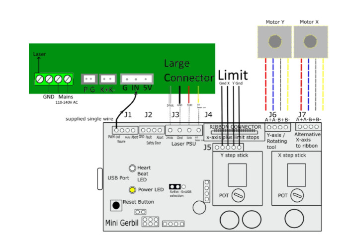
When a K40 has a Digital Control Panel (DCP) [actually called the PowerLED] here are things to know:
- K40 DCP controls the LPS’ power entirely separate from the controller.
- A DCP controls power by providing a PWM signal on “IN”. The PWM signal is derived by the DCP based on the power scale buttons and is represented as a % on the LED display.
- When the “Laser Switch**” on the DCP is turned off the DCP stops asserting the PWM signal turning the LPS power = 0. Note: This why the interlock loop has a jumper on it, it’s not used. In a non-DCP K40, the interlock loop is was wired through a Laser Switch. On K40 with a DCP the laser enable function really does not enable/disable the laser it just turns its power to 0.
- The controller controls the LPS power by providing a PWM signal on the L pin.
- Neither the LPS nor the controller knows what the other is doing…
Now let’s consider your current LPS set up:
- Your "IN signal is connected to the controller which can control power.
- Your “L” signal is connected to the controller which can control enabling the laser, power control, or both. I don’t know how the “Awesome Tech” controller is configured? But for now, this is not directly causing your problem.
- The DCP power control (the IN signal) is NOT connected to the LPS. As a result, the “Laser Switch” enable/disable function is also not connected and does nothing**.
- Since the DCP-IN signal is not connected to the LPS the DCP cannot control the power therefore the setting on the DCP display is meaningless.
Essentially your DCP is not connected to the LPS and that is why the Laser Switch has no effect yet the machine engraves properly.
Your laser power is completely controlled by the controller.
Are you willing to remove the digital control panel? It really isn’t doing anything the way it is.
I can provide instructions for a new panel that has a laser current meter, laser safety, Laser Test, and pot power control with a small digital readout.
Alternately we can consider:
- Wiring the DCP back up like stock but with the controller you have.
- Living with the current configuration with all power control and laser enablement from the software. IMO this makes the machine less safe and less controllable
- Some hybrid of the above…
So outline for me what functions you would like to have implemented and I will make a recommendation.
The good news is that now this problem is clear and makes sense! ![]()
4 Likes
Are you willing to remove the digital control panel? It really isn’t doing anything the way it is.
Absolutely. I have already designed a new panel that I would cut and install.
So outline for me what functions you would like to have implemented and I will make a* recommendation.
.I would really like to get my Mini-GRBL 2 installed and running. I want to get back to using lightburn
I can provide instructions for a new panel that has a laser current meter, laser safety, Laser Test, and pot power control with a small digital readout.
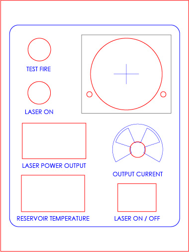
If you have something I can modify in Illustrator or SolidWorks. All I want is a mA, Power On/Off Switch, Laser On/Off, Test Fire and Tube Temp and Water Temp. I will post what I have designed in a bit
Here is the design I made and I think it will work. The blue box is the size of the opening that the current digital panel.
What kind of file are you trying to upload? SVG uploads should work and display, at least.
I recreated it as a JPG
I will be back with an answer in about a day…
Thanks Don. I am in NO hurry.
Also, I didn’t know you were the Don of Don’s Things Blogspot. I have been following you for months. Thanks for your help and your expertise.
4 Likes
Update,
Still working on your problem collecting some technical details.
However, here is what I have to date.
https://www.digikey.com/schemeit/project/k40-powerled-v30-PM4QJBO303GG
See the tab: MiniGerbil PaneI
I don’t like the Local/Program switch solution to power control, I am noodling a work around.
1 Like
I so appreciate all the valuable information and especially help. I am researching how to add the potentiometer.
I am in contact with AwesomeTech and we are testing an approach that uses a pot. Will let you know when testing is done.
3 Likes
Don, Paul (Awesome Tech),
You guys rock!. You can’t begin to know how much I appreciate all the information and solutions you are figuring out. I am eternally grateful.
Have a blessed and amazing Merry Christmas!
2 Likes
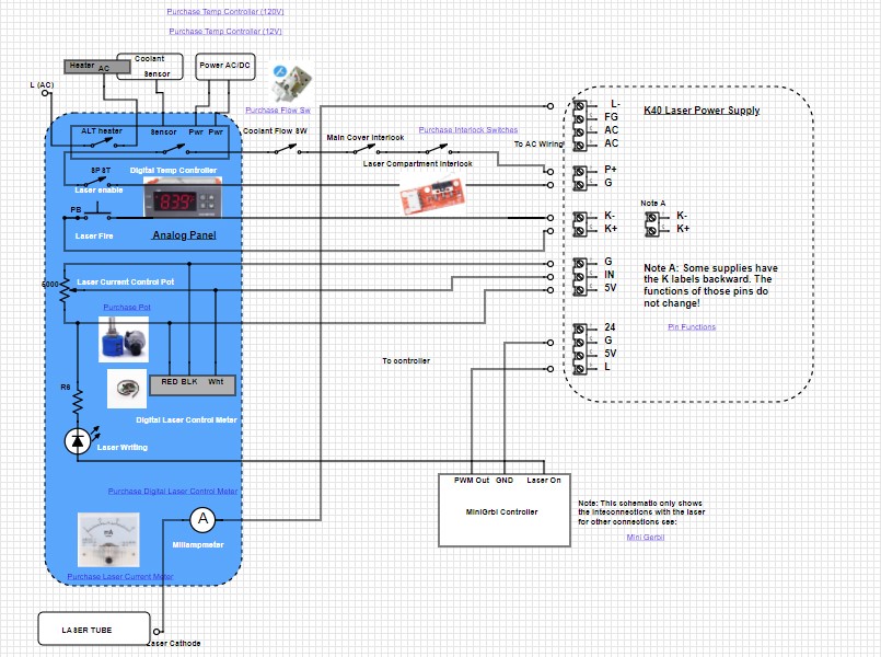
Here is the panel that we are considering/testing.
AwesomeTech is testing as I have no way to do such.
The key difference is that the PWM_OUT from the controller is connected to the LPS-L and the LASER_ON signal is essentially ignored.
In this schema, we are going to use the MiniGrbil " PWM_Out to drive the laser from the LPS-L pin. We will put a pot back on “IN” and also add the Laser Enable, Fire and interlocks.
We are not sure about some of the subtleties of this idea. You can do a simple test if you want to get started.
@mcdanlj format question; can we make the font red in by formatting tags?
Caution: if for some reason we have this wrong the machine could power on with the laser on!
Be careful when you power on the machine after making these mods.
- Remove power from the machine
- Disconnect the “Laser On” connection to LPS-L and insulate it. We are going to ignore this signal.
- Disconnect PWM_OUT from the LPS-IN and move it to the LPS-L
- Connect the “IN” pin to 5V. Caution this will set the laser to full power. Alternately you could install a pot as shown in the diagram.
- Make sure you are “safe”, wear protective eye gear
- Turn on the power of the machine.
- Run a cutting job of something simple to see. Like a square:
-
- Does the job image correctly?
-
- Does the job start and stop normally?
1 Like
Thanks Don and Paul…I will be digesting this carefully before attempting.
Again…you guys are the best!
1 Like
Don, Paul,
I got it to work brilliantly with the Mini-GRBL. I didn’t do any of the other modifications you mentioned…not that I didn’t want to attempt…I just wanted to get Lightburn up and running.
Paul, Can I make a constructive observation. The X and Y connectors wouldn’t fit both plugged in at the same time…the plugs were to large. If the board was about 1/8" (3.125mm) wide, and the plug was moved out it would work perfectly. What I had to do was plug one in (Y axis) and then use extension wires (like the ones you provide for the PVM but with a male end and a female end. As soon as I did that, and got them plugged in correctly, the machine lit up (after I plugged it in). I successfully ran and engraved Lightburn and the power and speed controls WORKED PERFECTLY!.
Thanks again. I will attempt those other modifications later because I really want the Potentiometer choice.
1 Like
Nice!
So you got it working with the mini Gerbil but the digital control panel is still not controlling the power correct?
I assume that the PWM out is now connected to “IN”?
Don,
Yes, the digital panel is NO longer functioning. I put some tape on top to remind me…LOL.
That was the issue last time when I tried installing the Mini-GRBL last time,I wanted the digital panel to work while using Lightburn. I guess I wasn’t ready to give that control up at the time, which is funny because I was using a Diode before that and used Lightburn to control all the power.
Anyway, I can’t begin to thank you enough for all the time and effort you pput into helping me. I am going to do the potentiometer soon…but first, my camera for Lightburn is arriving on Wednesday and can’t wait to put that to the test.
Thanks again.
1 Like
OK, let us know when you are ready to put the new panel in.