For those of you struggling with stock k40 and Corel/Whisperer, bite the bullet and upgrade the controller and software. I installed a mini gerbil and purchased lightburn and it makes the k40 feel like a much higher end laser experience. Everything is so much easier and quicker to use. 95% of the design. And prep can be done right inside lightburn without the need to constantly save and refresh. The framing capabilities and cut optimizations alone are worth the $40 for lightburn.
4 Likes
I have a mini gerbil. Unable to get it to work. Awesome tech tried to help. They said all the voltages were good. They decided it was a grounding issue. I have it grounded to a large copper rod about 4 feet in ground.My electrical box is old 100 amp box. No ground on plug. Help
Totally agree. Whisperer is a great piece of software and I had eliminated the need to do anything with Corel Laser and my copy of CorelDraw which came with the machine which seems a little questionable in how it came with the machine as I purchased the machine secondhand.
I have the original Gerbil and it works with lots of other software including Lightburn which opens up a lot of opportunities. I design a lot of stuff in 3D and use .dxf to move date from cad to laser cutting software anyway.
Ground and Neutral also are tied together at the box. Neutral is usually the white wire, but be careful to check first as you may have such an old setup it may pre-date coloring conventions used today in households.
If you give us a little more information, we might be able to help. What is it that the board is not doing? What are the symptoms? What software are you trying to use and communicate to the board with? The more information you can provide, the better we can do to help.
1 Like
I have some health issues and on internet issues. My messages would not deliver. I hope that issue is resolved. I still need help
The laser head will go thru its motions without firing. The test button will fire laser at home position. I tried holding test button during laser run will not fire.Am using mini gerbil and lightburn
How is your controller connected to the Laser Power Supply.
Provide a drawing and/or pictures please.
Did you fix your grounding issue?
Another thing to check… In Lightburn-> Edit-> Device Settings you need to make sure the S value max to be the same as $30 parmeter. Check $ settings by typing $$ in the console. Once these are lined up then if everything else is working fine you should be able to fire the laser.
Gerbil fires with M4, I did not get M3 to work for at least the original Gerbil. It could be due to gcode having M3 command with a S parameter is not interpreted in the firmware. But in any case, get $30 and S value max aligned.
Also on the K40, I don’t believe the test button works at the same time as the PWM output of the gerbil is connected to the power supply.
Tim
1 Like
I think the laser test button on the supply or the test button on the control panel will override anything coming from the controller.
I do not understand: “The test button will fire laser at home position. I tried holding test button during laser run will not fire.”
First we should determine if the laser fires without the controller.
Will the laser fire with the test button down on the supply?
Will it fire with the Laser test on panel?
Hi Don, I know you’re very well versed with the K40 electronics.
But in this case you disconnect the wire from the pot to the power supply during the gerbil installation. Then you connect the PWM output of the gerbil to the power supply (same place the pot was previously connected). This renders the “Test” button on the panel useless. If you don’t disconnect the pot from the power supply you could be loading the PWM output of the gerbil with the pot and that’s not a good thing.
So without a DPDT switch you need to manually disconnect the PWM output of the gerbil and reconnect the pot to the power supply. Then you can use the Test button on the panel to fire the laser. In order to use the controller afterward, you need to reconnect the PWM output of gerbil to the power supply. Either way you should only have the pot (which enables the panel Test button) OR the PWM output of the controller (which disable the test button) connected to the power supply.
@Timothy_Rothman In my opinion, these are bad insallation instructions.
The POT and test button should be left connected and the PWM signal should be fed to a different pin of the LPS. On the original K40 and most other controller boards, the PWM is fed to the L pin via a MOSFET that pulls the pin to GND to fire.
What @cprezzi said.
Can you point us to the instructions are you referring to above?
Most of us have stopped using the “IN” pin (pot control) irrespective of the instructions you will get from many including Chinese LPS manufacturers.
Alternately you should use the IN pin driven by an open drain on the controller board for the PWM.
This leaves the control pot intact and for operation there is no need to swap any wires.
I am a bit surprised with your setup as removing the pot will not disable the test button? The test button and pot are supposed to be on different circuits?
Can you provide a schematic of your LPS wiring?
You are both correct as it relates to the Original K40 controller and some other controllers, but as I stated it is in fact the setup for original Gerbil (newer Mini Gerbil may be different). Here it is from awesome.tech website and is recommended setup by Paul based on his original design and may have changed for Mini Gerbil.
Yes, it is also that way for the miniGerbil. Paul at awesome.tech has always used the IN terminal for PWM control.
Reset
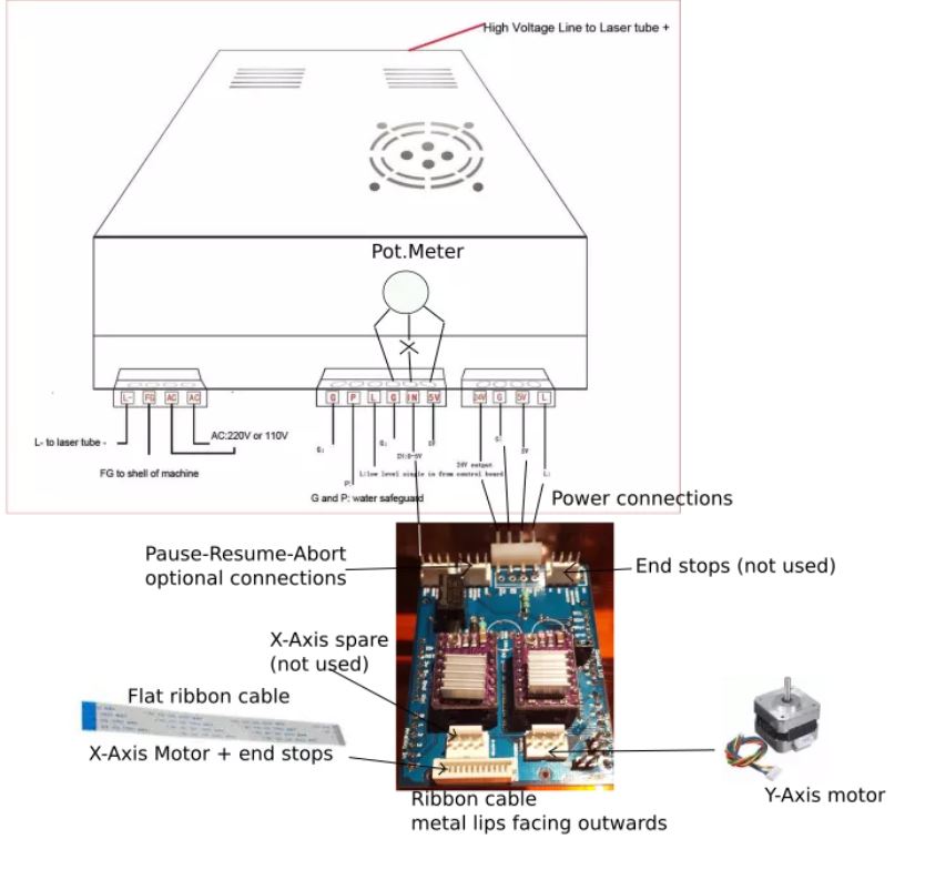
From Pauls @paul website this diagram shows how Paul is recommending connection.

In this configuration I interpret that:
- the L pin provides on-off control (enable) of the laser.
- the IN pin controls the power via a PWM signal
Since both L and IN control the PWM characteristics of the LPS this configuration will work fine. [this statement is not exactly correct but good enough for this discussion].
So relative to @Badlaser43 's original problem:
- This configuration should work if wired correctly
- The test button should work with the IN and L pin connected as shown in the above.
Some clarifying background [in case I confused the discussion]
Unlike smoothie boards the mini-gerbil PWM output can drive the IN pin directly as it is 5V logic. For smoothie boards internal 3v signals cannot. This is the reason that smoothie configurations are best implemented using the L pin driven from an open drain driver. The control of the lasers on/off can be implemented using a driver mosfet & relay in the interlock circuit configured as a switch.
The only disadvantage of this IN pwm approach is that you loose the manual power control pot. However you gain simpler and auto-magic programmatic laser on/off control.
I generally do not recommend programmatic control of the lasers ON/OFF state as it is not fail proof and gives the operator a sense of safety that could be erroneous. I do not want to trust my eyes to software.
…
Why is a pot necessary!
The pot is a form of overall intensity control.
It has been proven [at least to my satisfaction] that you need the pot to be independent of the programmatic control of PWM because as the tube wears the set point of the LPS needs to change. This is also true for engraving from material to material.
However, if its suitable in your workflow to have to change the programs power settings each time you rerun a job or change materials then having a pot may not be an advantage.
Note: the diagram above show how to implement a remote-local switch for the pot or digital control panel.
1 Like
@donkjr, thanks for the updated diagram. As I said earlier, I know that you’re an expert on these machines, but the gerbil setup may be a little different in this area. You and @cprezzi may be recommending a better way to connect, but it’s likely @Badlaser43 is having problems with the default installation. Also what is the L pin, can you identify it in the diagram posted above???
Per the gerbil standard installation posted above I verified that anytime the gerbil PWM is connected to In on the LPS the test button on the panel does nothing. When you disconnect the gerbil from the In on the LPS, the test button on the panel test fires at around 10mA (this is with the sweep leg of the pot disconnected and nothing is connected to In of the LPS), when you connect the sweep leg of the pot to In of the LPS, the test button on the panel fires according to the setting of the pot (from 0mA to up to 18-20mA).
So I think the advice to disconnect the gerbil PWM to get the Test button working may also apply to the mini-gerbil in question.
Also the S parameters definitely must be checked (aligned as I mentioned) because Lightburn does a great job, but does not configure device settings when you select Gerbil. Paul wanted $30 to be a way to control intensity for greyscale, but it can be confusing as he sets default to 2048 and if LB is setting S max value to 256 or something typically low, then it seems like nothing is happening. For 8 bit greyscale it’s easier to just set $30 to 255 and then black (255 on a scale of 0-255 would get full power), but if you set the layer to 50% power in LB then it will give S128 in the GCode.
Sorry, the L is actually the LO pin in the diagram above.
I will go back and look at the LPS and min-gerbil schematics to see if I can explain the behavior that you verified when connecting/disconnecting the PWM to the IN pin as you suggest
Behavior #1: Perhaps when the PWM pin is connected to the IN pin it is holding it to ground until the PWM is asserted. If this were the case the TEST button would fire at 0 power and therefore look like it did nothing.
Behavior #2: When you disconnect the Gerbil PWM from IN the test panel fires at 10ma. At what level will the LPS fire if IN is left floating? Perhaps it is maxpower/2 = 10ma.
Both these behaviors is IMO further reason to use the method I outlined :)!
After rereading the thread, I agree that this may or may not be related to @Badlaser43 's problem. We should step back and collect some additional information from him to see if we can help.
When neither the pot nor PWM are connected to IN pin of the LPS and IN is left floating I get 10mA, When I connect the sweep leg of the POT to the IN pin of the LPS, the pot controls the power from 0mA up to around 20mA- I don’t run it that high… ever.
As far as connecting PWM to LO, you could be correct, but I will consult Paul just in case he’s doing something unexpected. Once he confirms I’ll wire it up that way and report back.
As you mention @Badlaser43 may have another issue.
So I think you verified behavior #2 works as I suspected, I was thinking from memory…
I will check on the PWM output …
I could not find Pauls handle on here …