Just can't get it — from frustration to success milling PCBs

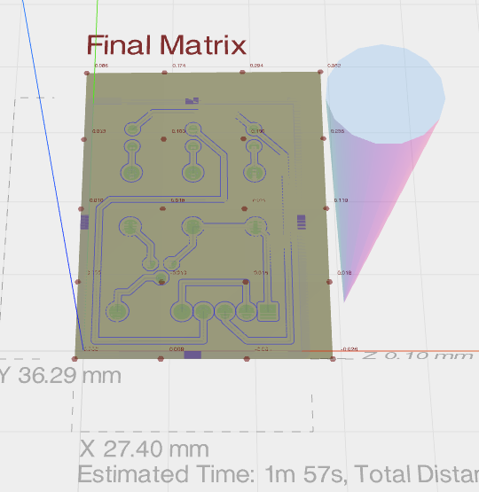
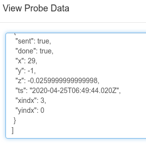
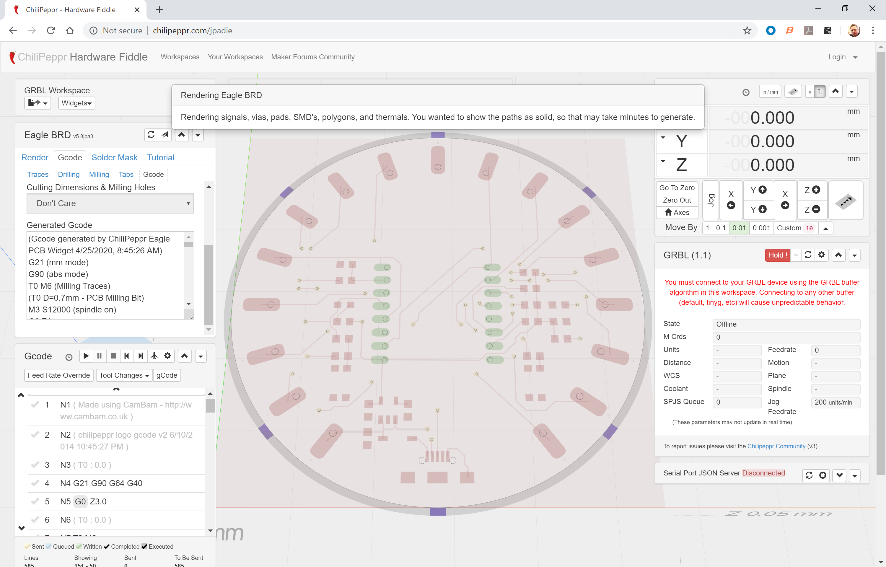
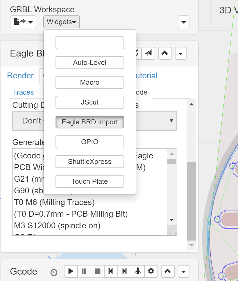
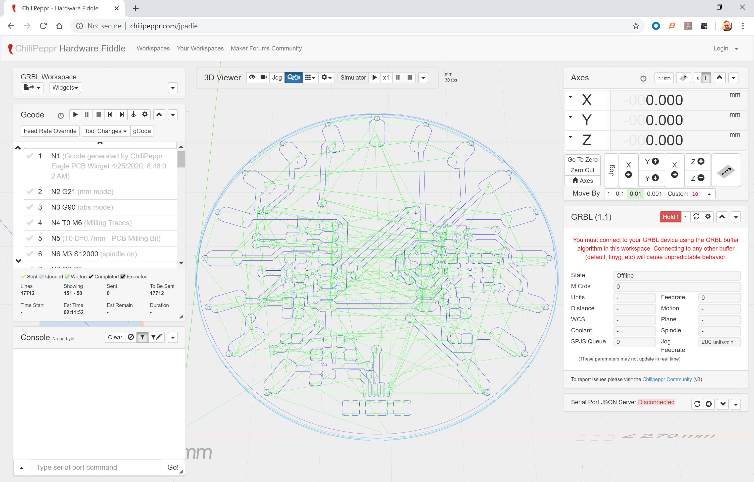
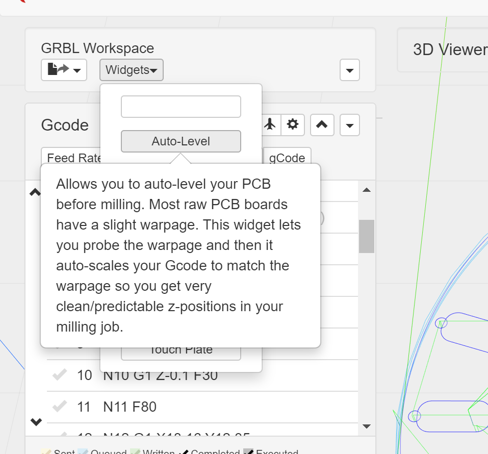
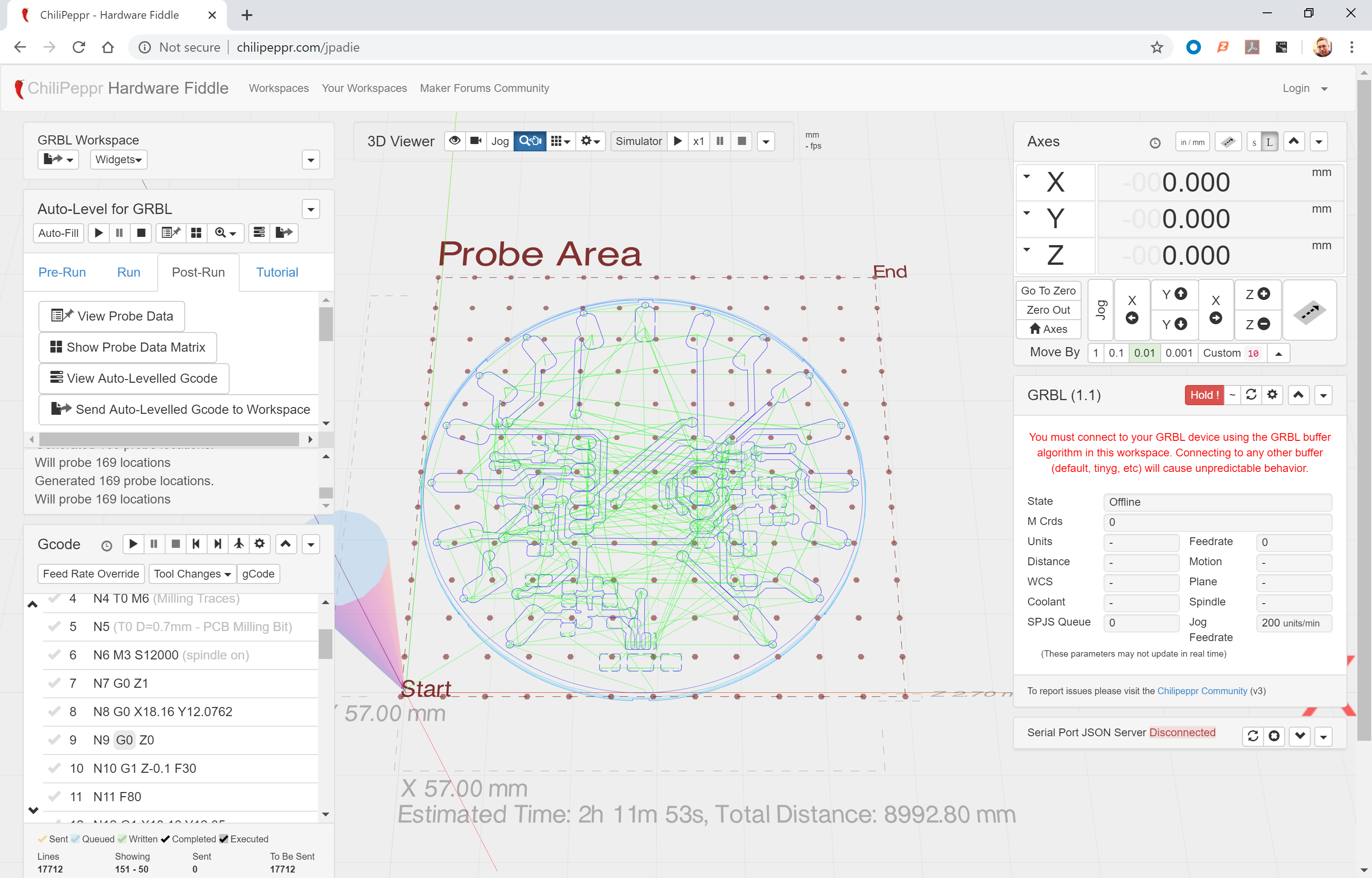
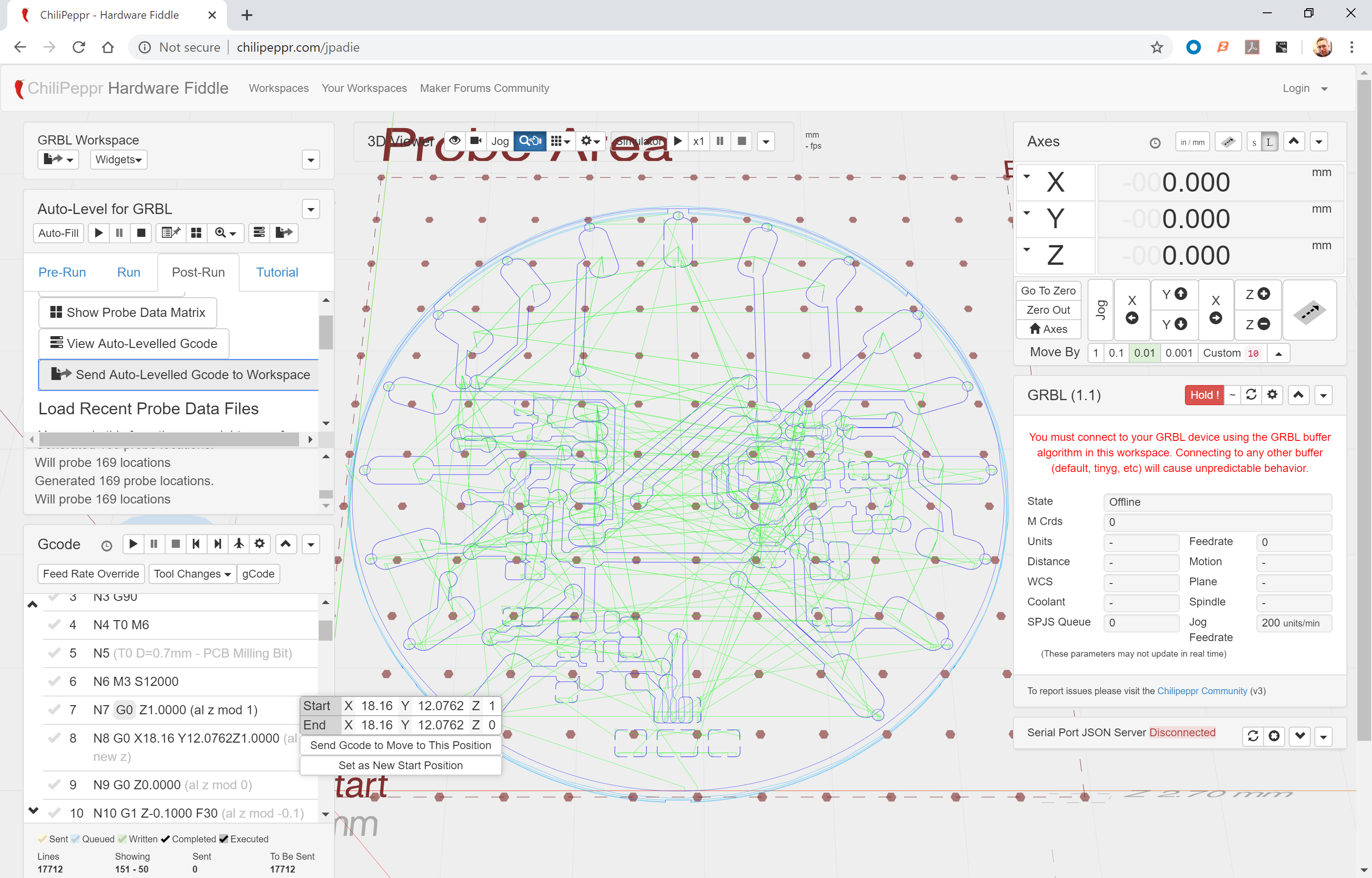
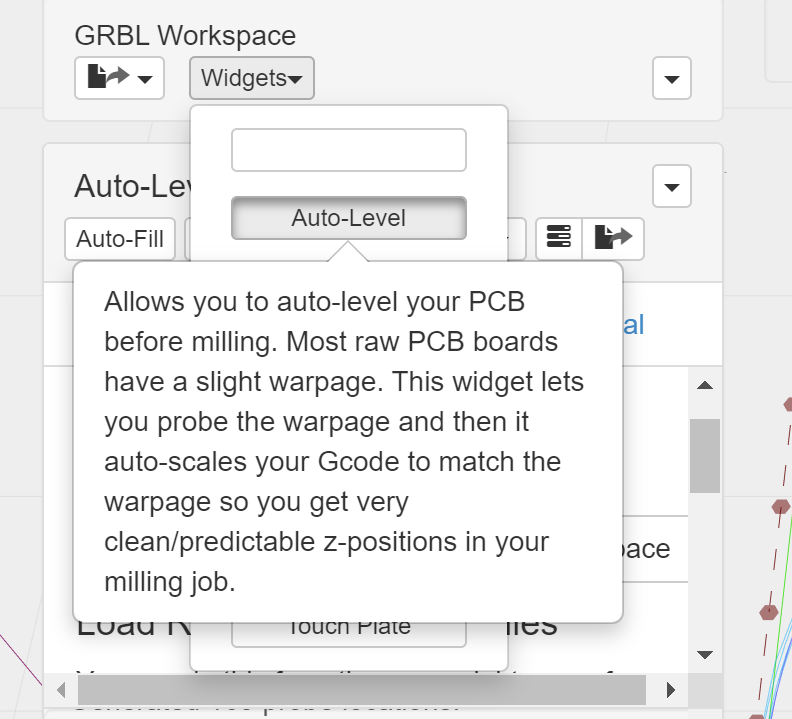
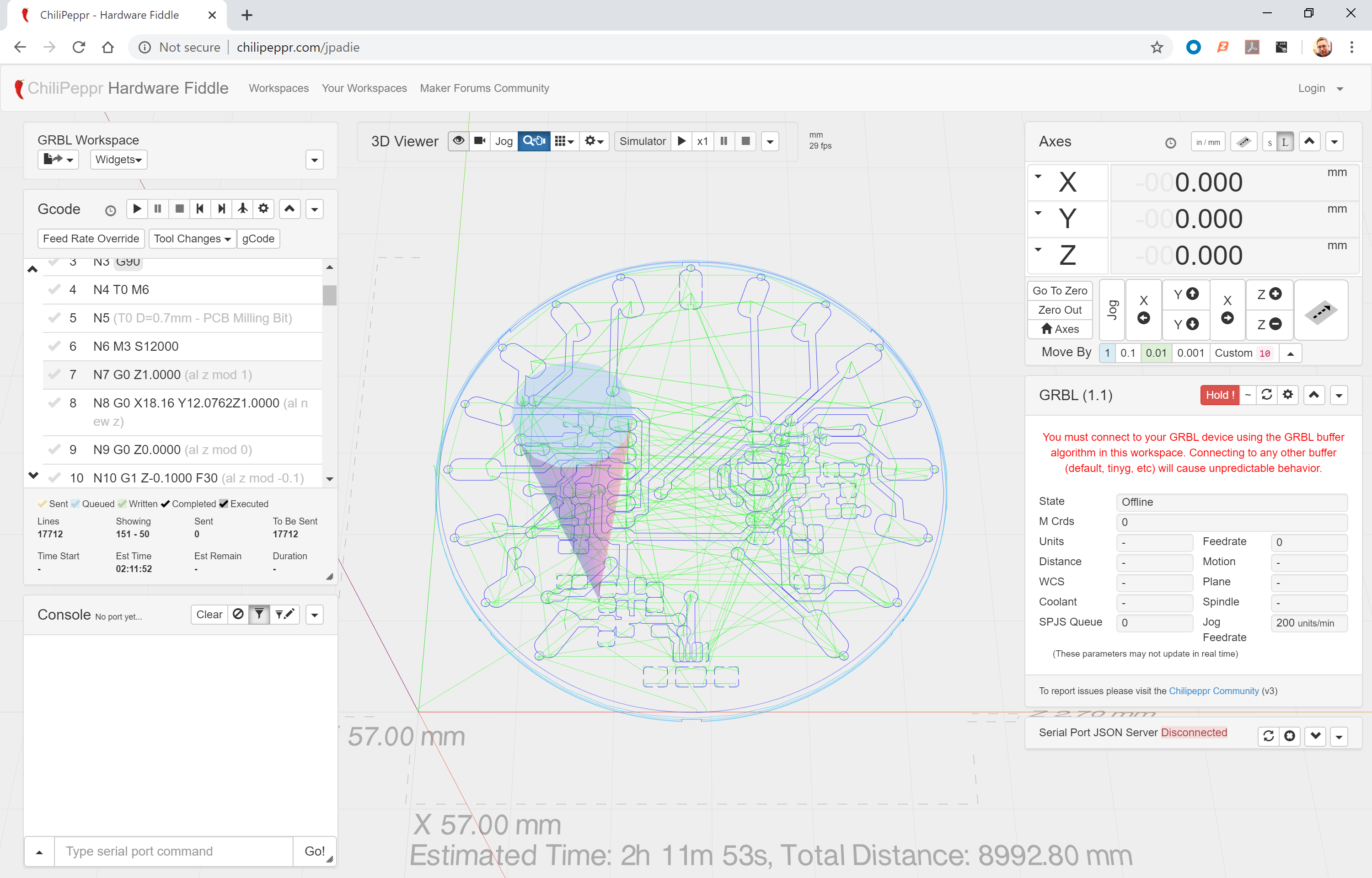
The Chilipeppr interface offers great ideas, and I was expecting to spend a couple of days using it and learning the best ways to run it. The import of Eagle files, with graphics indicating the import has worked and producing the outlines of the PCB tracks correctly, looked really good. Adding to that, Auto Levelling with probing that revealed the undulations of the underlying PCB in a neat graphics display was very inspiring.

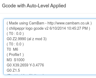
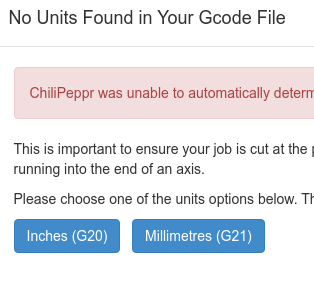
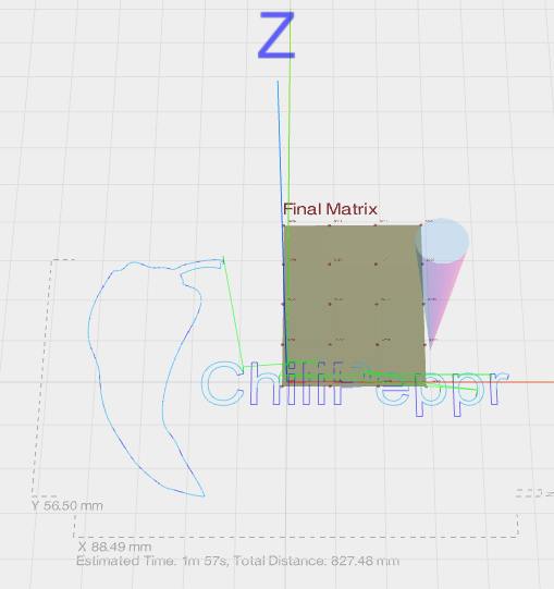
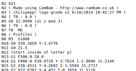
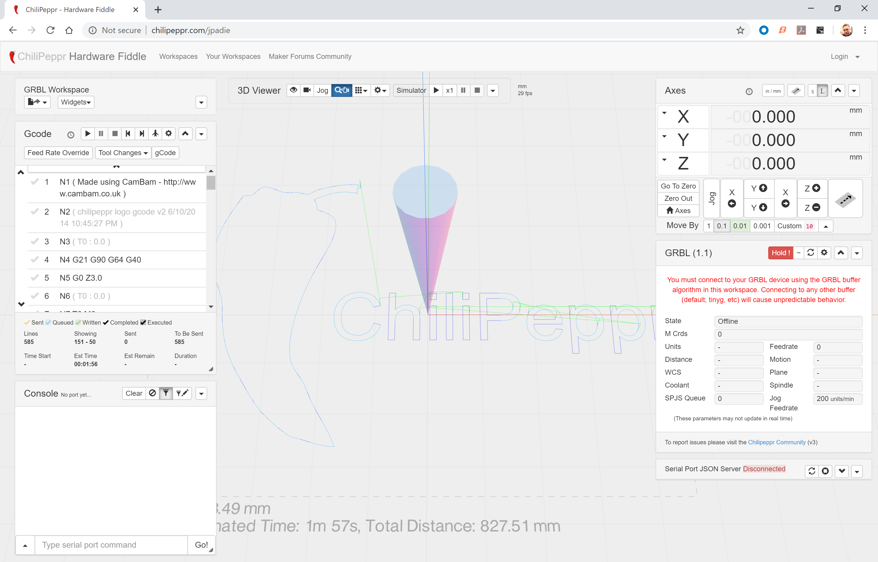
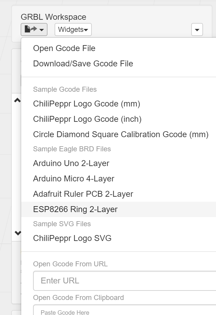
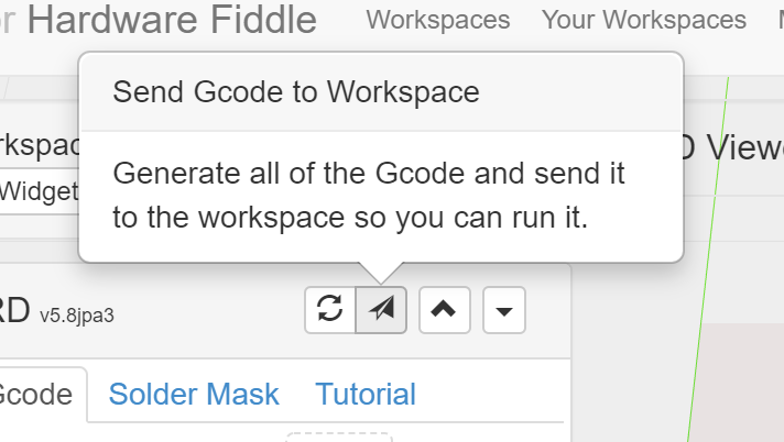
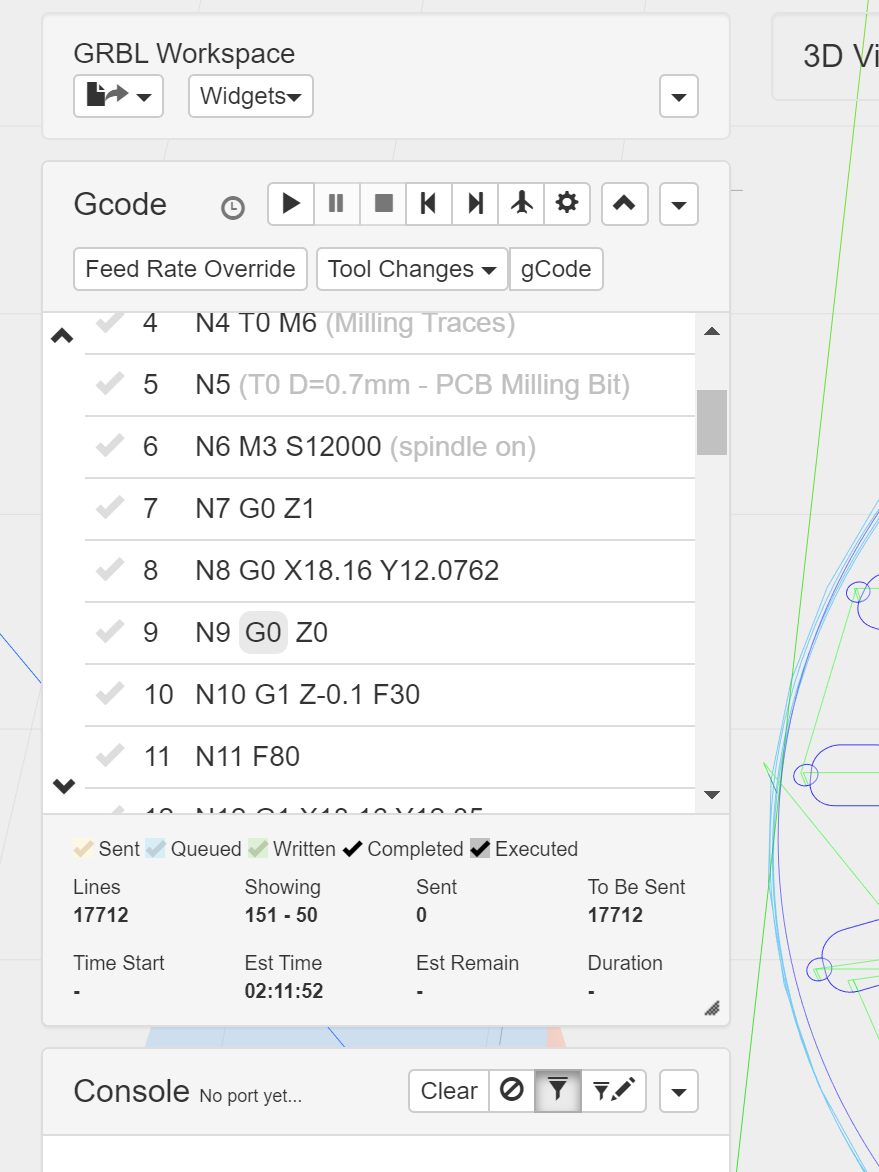
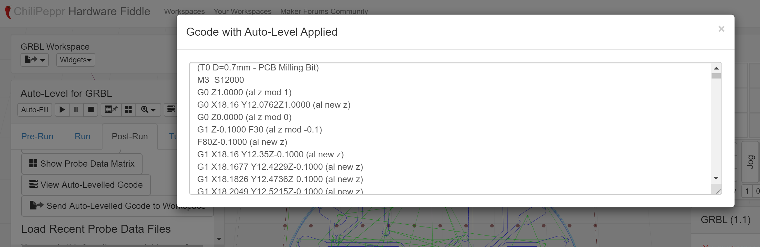
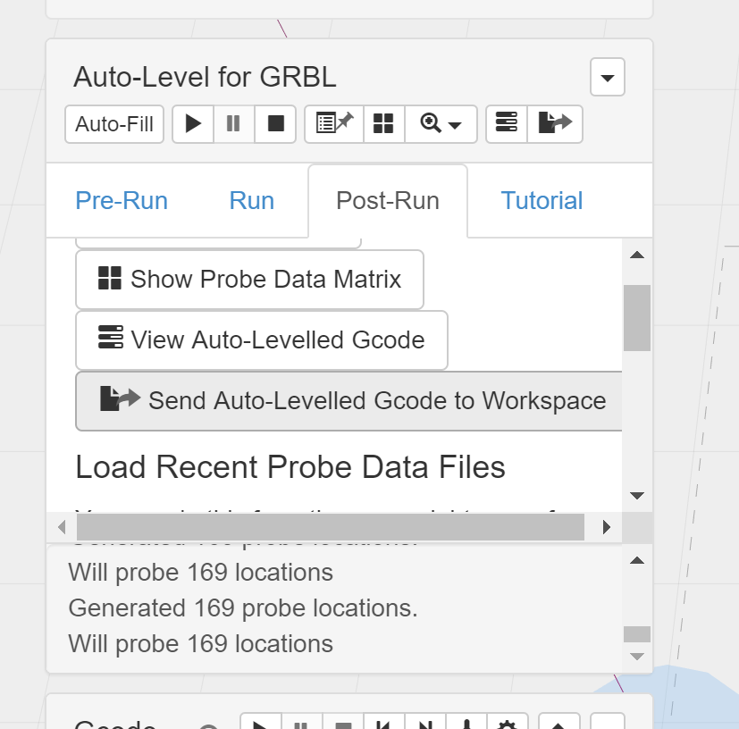
After 6 days of intensive work, I am still at a loss as to what is the best sequence to enter basic numbers to get a PCB engraved. I have just hit the reset button on a job that had my Eagle PCB on the screen, homed, gone to start of PCB, set to zeroes, Auto Levelled with probe, I went through and checked each tab and made what I felt were sensible choices on the Eagle import. Exported the “Levelled GCode” I could see in the preview “to the workspace”, and hit the GCode run button, and what do I get? Not my PCB, but somehow the ChiliPeppr demo logo thingy is still in there somewhere and it has started to engraved that instead.

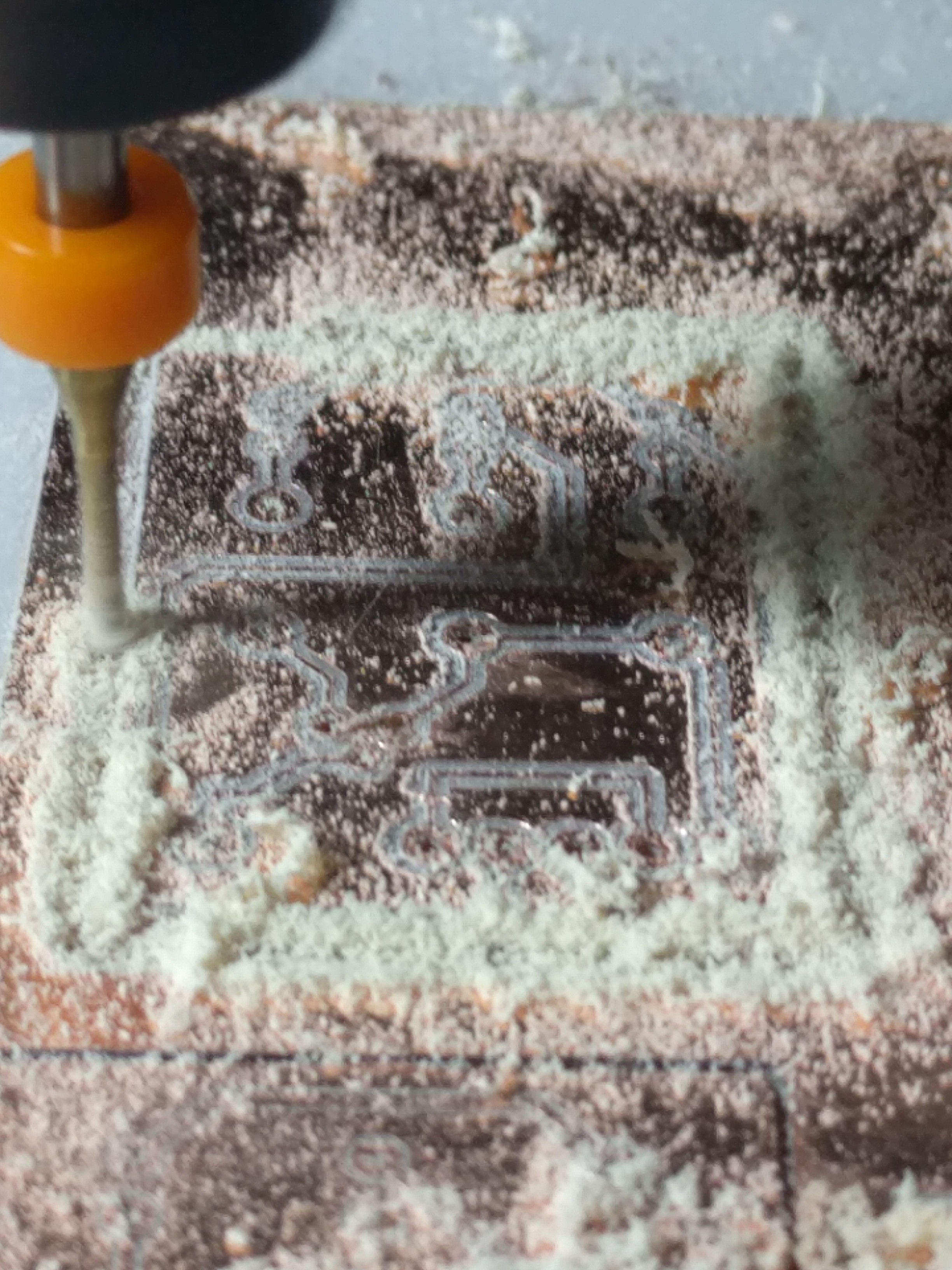
I am at a loss as to how Javascript, and in turn CP keeps track of what file it is using and how to anticipate what it is going to do. So far I have only had one engraving that actually used the Auto Levelling, though I have tried to set it up many times. Every time I go to check the G-Code tab, the CP Logo returns. How does it store settings? Some of my choices seem to carry over for a while then unexpectedly they revert back to the defaults?

One of the vouched advantages of Javascript is the Event based Programming. This all very well to cater for users who skim around trivial web pages and click on almost randomly connected data sets. However for me, trying to set a complicated, time consuming job methodically it is driving me mad. Everything works, no errors, but very little seems to work predictably together, the import, the levelling, the G-Code sender are so independent that they just don’t make sense or establish any hierarchy of control or decision making strategy.

Please forgive me if I have missed something critical, and I don’t intend to give up easily, but is there somewhere a straightforward explanation as to how to manage the workflow between these widgets successfully.

For example, just one question amongst many, should I always import the Eagle board before Auto Levelling probing, or the other way around? Which one? If there is a joe-bloggs everyday user out there who can help me I would be very grateful.

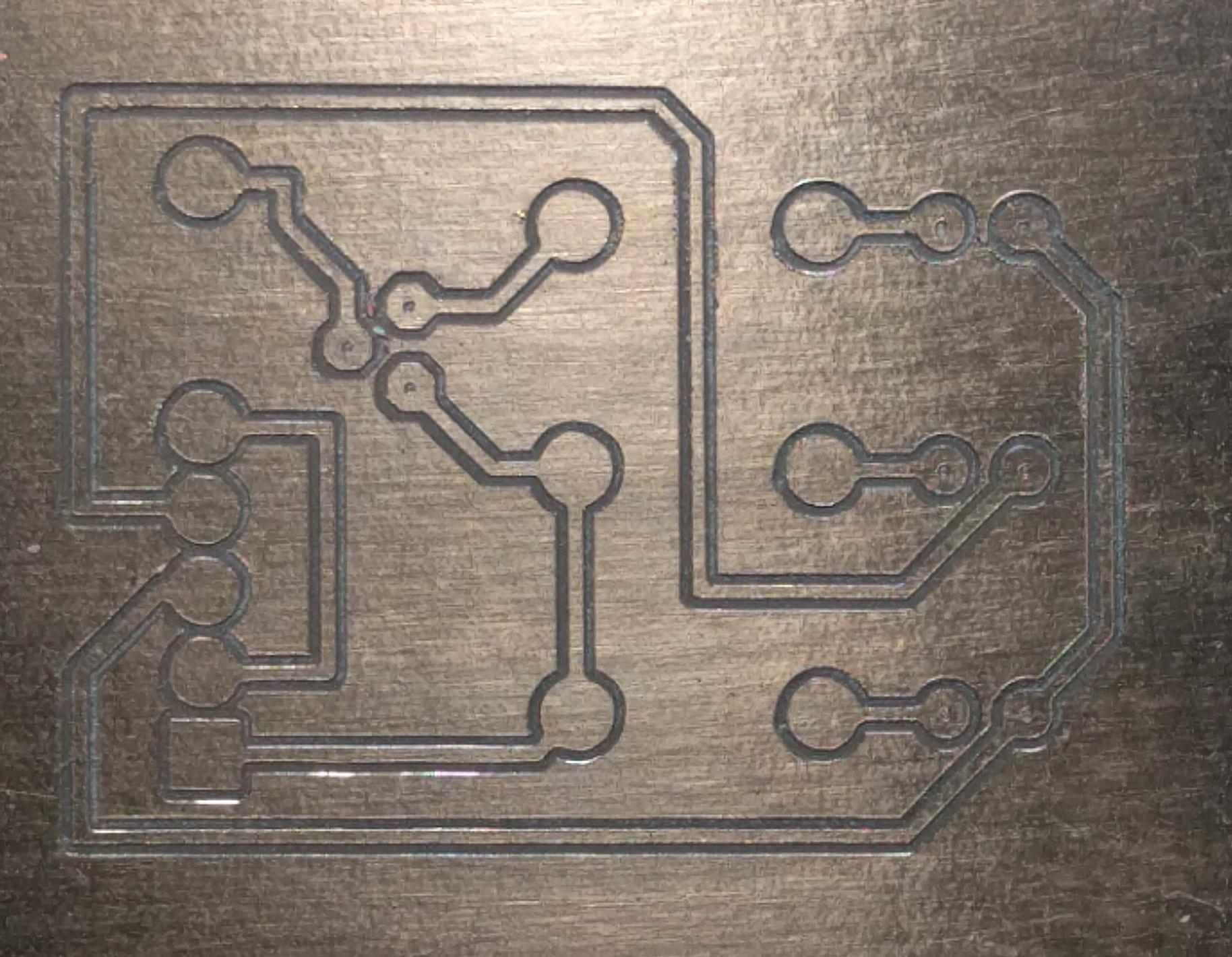
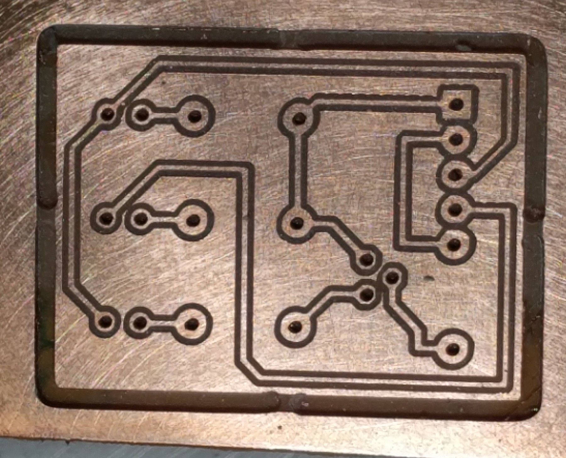
Success seems tantalisingly close, but I am yet to experience it.

RobW

Hi Rob,
I’ve been making lots of PCBs using chilipeppr and the eagle import so it CAN be done!

One thing that caused lots of problems in the beginning and might be your issue is cookies. Chilippepr uses cookies to store lots of information about your session. If these somehow get messed up weird things can happen. So one thing you can try is delete all the chilipepper cookies in your browser. Kill it and start up a new browser and run chilipeppr and see if that improves things.

If you don’t have cookies turned on in the first place you might also have problems. So if you have cookies turned off I would add an exception for chilipeppr.

If that doesn’t fix things then we can go over some more detail of what you are doing and try and work this out.

John S.

1 Like

Ok, will do. That sounds reasonable. Every person’s machine is different and when talking about browsers, it sure can can be “individual” there.
Thank you for your suggestions. I will report back.
RobW

Hi John,
I removed all “cookie” information from the Chrome records and as I have no banned sites it repopulated when I started up again OK. So I set about trying again with my test piece(27x38mm approx). I dragged the GRBL_indicators.brd file into CP.

image

That resulted in the board being rendered in the work space, and I could request that the lower side be displayed and mirrored about the Y-Axis.


The above image shows the PCB trace outline and the scanned topology readings. All this looks good and very promising. (I used a 10mm grid for a quick scan, and set it to show no amplification of the gradient). So now I look at the “Post Run” Tab and check the probe readings
image
Again looks reasonable (I guess I don’t understand that at all).
So now I check the Z-corrections to the GCode
image
I find it has the ChiliPeppr demo logo work loaded?

If I send that off to the work space I get prompted with this,
image
And when I click on “mm”, the GUI work space shows the CP Logo underneath my PCB probing data.


And if I check in the GCode widget for the GCode, I find this
image

What I don’t get is how the Eagle Import widget can get the right PCB data in, as I can see it on the GUI preview, it get its size right, it can select sides of PCB, it Y-mirrors it, and the Auto Leveller can scan the right area, BUT it can’t seem to overwrite the new job and transfer the leveler corrections into the GCODE area.

In its present state if I asked it to run in the GCODE widget it would do the CP logo job (again) and not the PCB I was working on. There must be something fundamental I just don’t get.

I am logged into the CP http://chilipeppr.com/jpadie site with my CP Password etc.

Any help, once again, would be greatly appreciated.

Cheers, RobW

Hi RobW,

I understand your pain. It does sound like you’re super close, but my worry was somehow you were encountering a bug, so I thought I’d give it a run-through in jpadie workspace to see if I could get a clean board ready to mill.

I start out with the famous ChiliPeppr logo.

I load the most complicated sample board file.

Looks good.

So I generate the Gcode for the board. Looks good.

You see the Gcode now combined with the Eagle BRD rendering in the 3D viewer. It’s kind of hard to see the Gcode but you can see blue lines representing it now.

Then I turn off the Eagle BRD widget to get the board rendering gone and just keep the Gcode that was sent to the workspace. I think this is the most confusing step.

After turning off the widget you can see clean Gcode.

BTW, at this step I tend to just mill the board. I’ve found auto-levelling so frustrating through the years, I just keep re-milling over and over running the same Gcode to get the copper milled deeper and deeper on an iterative basis until all isolation has been achieved. Of course auto-levelling is the coolest way to do it, but it’s just so slow and I’ve broken so many bits due to the electrical signal failing during probing and I’ve been too lazy to upgrade to say a 12v probing system into my TinyG. 3.3v just doesn’t run through milling bits all that well.

Ok, now that I have my Gcode ready to mill notice the Z levels in it just for reference prior to auto-levelling.

Turn on Auto-Levelling widget.

You get your probe area auto calculated.

I’m just going to use empty probe data for this example.

I can view my auto-levelled gcode in a popup window. Sometimes I just cut/paste this to a notepad text file to store on my computer. I could even drag/drop that in later.

Now I’m going to send auto-levelled gcode to workspace.

Ok, the new gcode is there in the workspace. You can tell by looking in the Gcode widget and seeing how there are comments on each Gcode line that had a Z like line 7 that now says “N7 G0 Z1.0000 (al z mod 1)”. You should now turn off the auto-level widget to get it out of the 3d viewer.

Turning off auto-level widget.

Now you’re ready to mill.

3 Likes

Thank you John,
I really appreciate the time you have put in here. That work flow has highlighted some small things that have tripped me up, but also solved a major confusion I had in my mind about how the data flowed from one widget to another. Essentially the job must be built in a linear fashion, all the import Eagle stuff set up (drilling, milling etc) and completed, then passed to the GRBL “buffer”, and then the Auto Leveling discovers a Z-Height grid and the widget has to read the GCODE from the GCODE buffer, apply the Z-Height Adjustments, and then it has to be told it has to return it ot the GCODE buffer.

I am pleased to say I got a reasonably good PCB from the last run for tonight.


I turned off most of the Eagle Import options to drill holes and milling out the board to keep it as simple as possible. I have a little arrow stuck to my Z-Axis motor and it did not move while this was being cut, so somehow I have not got the Auto Leveling working just yet.

However from these results, I take your point about the Auto Levelling (especially for small boards like these) that it may not be worth the trouble. However I feel I cannot rest until I am able to use if I want to. It is like the Holy Grail of PCB Milling!!
image

However, I am now inspired to return to it tomorrow with renewed enthusiasm. I have documented my work today in even greater detail, using your advice and will return that document to you for you own purposes. I am a retired secondary school systems electronics teacher and accustomed to producing step by step documents. It helps me clarify my own thinking and hopefully will help others as well.

I WILL master the levelling first!!!

So what was my major problem? I did not clearly stick to a process where every adjustment necessary for a widget was made in that widget at that time only, the milling data is passed from one to the next, and I cannot return to widgets I have used previously and hope that adjustments I have made will somehow miraculously update through the work flow. Now that I know the sequence, I need to practice.

Just a question to keep me going, how is it possible to set my own defaults, or do I have to set those each time I start the system up?

Thank you for attention to my difficulties, I hope to reward you with a good document that will be of some use to you.

Cheers, RobW

1 Like

Your board looks excellent–almost perfect.

Keep in mind if you do need to change something you can re-open the Eagle widget and regenerate your Gcode. However, you do then need to re-apply your auto-level data. The Auto-Level widget does remember your probe data, so you can re-apply it without recreating the probe points which is the slow part.

It sounds to me like what confused you the most is that Auto-Level physically modifies your original Gcode.

Glad you got it all working.

2 Likes

Yes, thanks John for your patience and assistance. I feel like I am controlling it, rather than the other way around.

I have now got to the point where I would like to be able change tools, so I can use an Engraver (30 Degree, 0.1mm) bit for tracks, a 0.9mm for drilling holes and a 2mm milling bit to release the board. I have been unable to get it to halt properly and carry this out. More study required.

Tonight I ran into a weird problem. I imported my Eagle .brd file and it appeared OK, I could choose options and move it into the work space and the now familiar blue lines came up on the overlay. However I could not transfer that file into the primary workspace with either the Folded Paper Plane (Eagle Import) or the Auto Leveler “Send Auto Levelled GCODE to work space” button. Both the GCODE button on the GCODE widget and the “V” would NOT reveal any GCODE at all , it was empty. I had to shut down Chrome and reboot the machine to get it work properly. Very weird. So I am not completely confident I have mastered it.

I would really like some way of saving my settings so I could really home in a particular way of doing stuff and know that I have not overlooked replicating a particular setting. It makes it easier to know that for a particular run, that I have only changed one thing and not just simply forgotten some. Good science is to only change one variable at a time.

Lastly the other thing that I find very confusing is the loose use of “Work Space”. There must be about 5 different ways this term is used. For example it is used in the overall title of the App. It is used as the description of the holder of the GCODE in the GCODE widget. There must also be a workspace in the Auto Leveler as we can see the altered GCODE before we send it to the GCODE widget. Plus the Eagle importer appears to have access to the GCODE widget workspace or does it have its own and then send it to the GCODE widget with the paper plane Icon? The flow of data between these workspaces is quite confusing and it made my initial efforts so frustrating, I could not visualise what was going where and what had been done to it in this transfer. Just having one common descriptor “workspace” when most likely it more than one storage area is highly confusing.

Sorry to sound so picky, when there is so much “goodness” distilled into this software, but I like to repay people’s work with constructive criticism. I am adding ot my notes on how use the software and I hope to contribute that to you very soon for your consideration.

Once again, thank you!

RobW

Just a quick catch-up from yesterday. I got the Auto Level to work ok. However the board was quite flat and the Z alterations were so small that I could barely feel the Z motor moving. So those corrections are probably at the limit of what my system can resolve reliably anyway. This adds weight to your idea that for simple, smaller boards Auto Level may not be that advantageous. On the plus side, it certainly does help look at the process objectively though.

I am using light weight phenolic boards (1.4mm), and possibly the double sided tape, which is pretty tenacious, is sufficient to flatten it out. No idea what gauge copper as I ordered them so long ago. When I get more confident I will get some higher quality Fibre Glass.

Cheers,RobW

1 Like

I feel I have finally got it, because I have finally a piece that I have used Eagle Import, Auto Leveling and Tool Changes successfully to make some thing useful. So from an engraving bit, to 0.9mm drill bit, to a 2mm Milling bit. It seems a long journey, but probably only more stressful because of the Corona Virus circulating around us at the moment.

I damaged my last engraving bit just before this run (10 more on order), but it still looks pretty good. I am documenting my journey as I go to be able to share with other Newbies (ie GRBL+Chilipeppr+Eagle). It is a tricky path, and not much room for human error, and certainly requires more intervention than 3-D Printing.

In action!

Things are looking up,
Many, many thanks folks.

RobW

2 Likes

I updated the summary to make it more likely that the next person who is frustrated finds and reads this. Feel free to update it further with that goal in mind! :smiling_face:

1 Like

Nice work. The PCB looks great.

1 Like

Thank you Michael, your help was essential to my progress. I have written up my own set of instructions. Probably to verbose, but I have tried to gather all my own thoughts and trials and tribulations, especially where my own ignorance was the root cause. So far it is 20 pages and 5000+ words. But it also tries to cover the GRBL variation as well as the particular machine I worked on. The amount of time I spent (I won’t say wasted, as I learned a lot of non-helpful stuff) looking for answers made my progress with GRBL+Protoneer very frustrating.
Anyway I am going to release from my Git-Hub pages and link back here so you can check it out and give me some feedback on it. I hope you like it and feel it is responsible contribution to helping you guys to help to others. Hopefully it will speed up other people’s progress.
Cheers, Rob

3 Likes

Hi John,
As I promised I have put my experiences down on “paper” and posted the document at my GIT-Hub site. For some reason my screen shots are rather washed out, but they are there.

I have tried to make a comprehensive “how to”
a. get an Eagle design into ChiliPeppr,
b. set up milling steps,
c. set up a GRBL system with good noise immunity,
d. use the GBRL Probe for Z-Probing and initialising tool heights ,
e. perform Auto Level if necessary,
f. running the mill,
g. managing tool changes,
h. finishing off the board.

I had to use the procedure, outlined by you guys in detail, to get my head around it and make my first PCBs successfully. So because it is based in Chilipeppr I have relied on your assistance, to a large extent, to create the document. I have tried though to help GRBL users more specifically and a good half of the document is about describing how GBRL+Arduino+Protoneer systems achieve good results.

I struggled to find any document like this at the time and I feel I am probably going to help others who are coming down my path. So I hope you don’t mind me putting my own spin and to a large extent replicating your advice and support (accurately I hope) and from the view of a first time user who needed a lot of hand-holding.

I look forward to be an active member/user of your software base. If you notice any problems with the document can you please let me know and I will endeavour to clear them up.

Cheers, Rob

3 Likes

That write up is awesome. Love it.

2 Likes

Thank you, I hope you will find it handy to refer people to it is necessary. If they reports errors or omissions I shall endeavour to fix them ASAP!
Cheers, Rob W

3 Likes