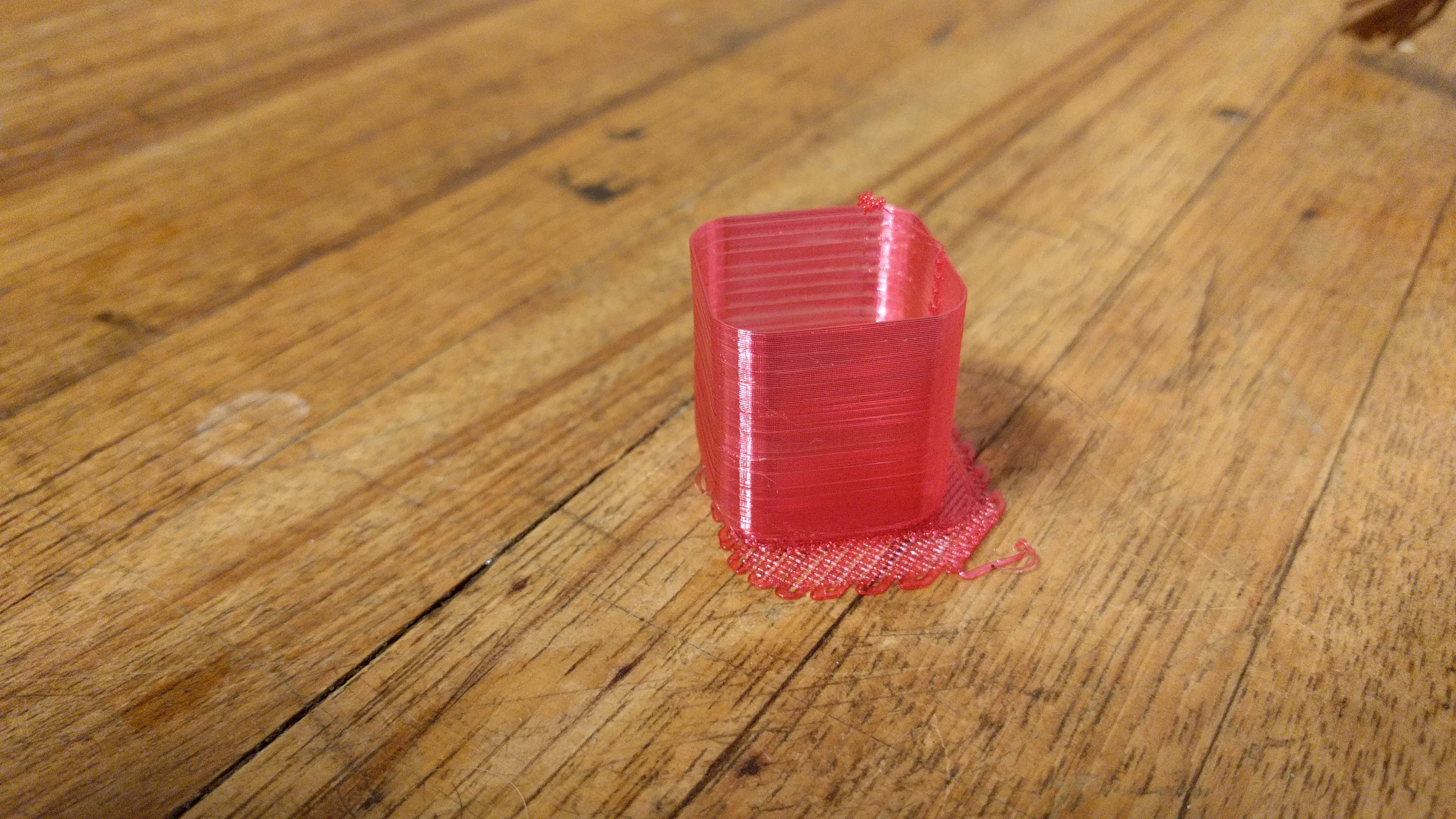
Its not pretty, but its a print. A trainwreck it might be, but its a print.
Thanks to all for their help and moral support. Thanks to +Eric Lien as well for shepherding in this adventure.
Its on a raft b/c i could not get the bed leveled out to my liking.
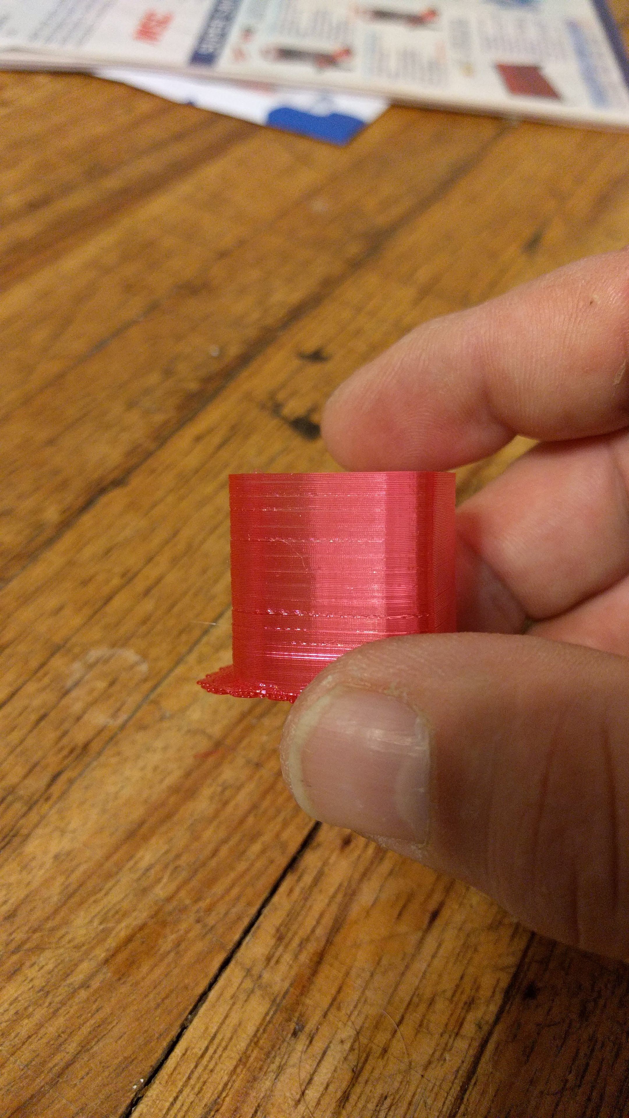
I have some sort of artifact at 2mm spacing, it really shows up on the inside, but not on the outside so much. It almost looks like the layer at that increment is just a hair too high. As these are TR8x8 screws, I am guessing it occurs at a 1/4 revolution point. Or there might be a burr in the nut somewhere. I am not sure I like these anti-backlash nuts yet. Unlike a machine tool way screw, they will never really force reversal and the weight on the nut will always be ‘down’ so I question their need.
The bottom shifted clear off the raft. Not sure what happened or when, but it overhangs off the raft. I am going to run the break-in codes a little while longer.
I took the plunge and live tuned the TMC2100 drivers before I printed. I don’t think its motor or driver related. I have an 80mm silent case fan blowing on the drivers, but I should check temps.
I probably didn’t do myself any favors picking the Magenta Inland-e/Sun for a first print as it supposedly nasty stuff, but I print fine with it otherwise.
Makes me appreciate the prints i get out of Di3 even more. I have a way to go, but seeing something finally coming out of this.
I like the Trinamic drivers for a lot of things, but on higher weight gantry printers like Eustathios and HercuLien… I have had less luck. Perhaps on a board like the Einsey, or DuetWifi where they are on the board and have better heat spreading potential they work fine. But on a socketed driver, I have had heat issues.
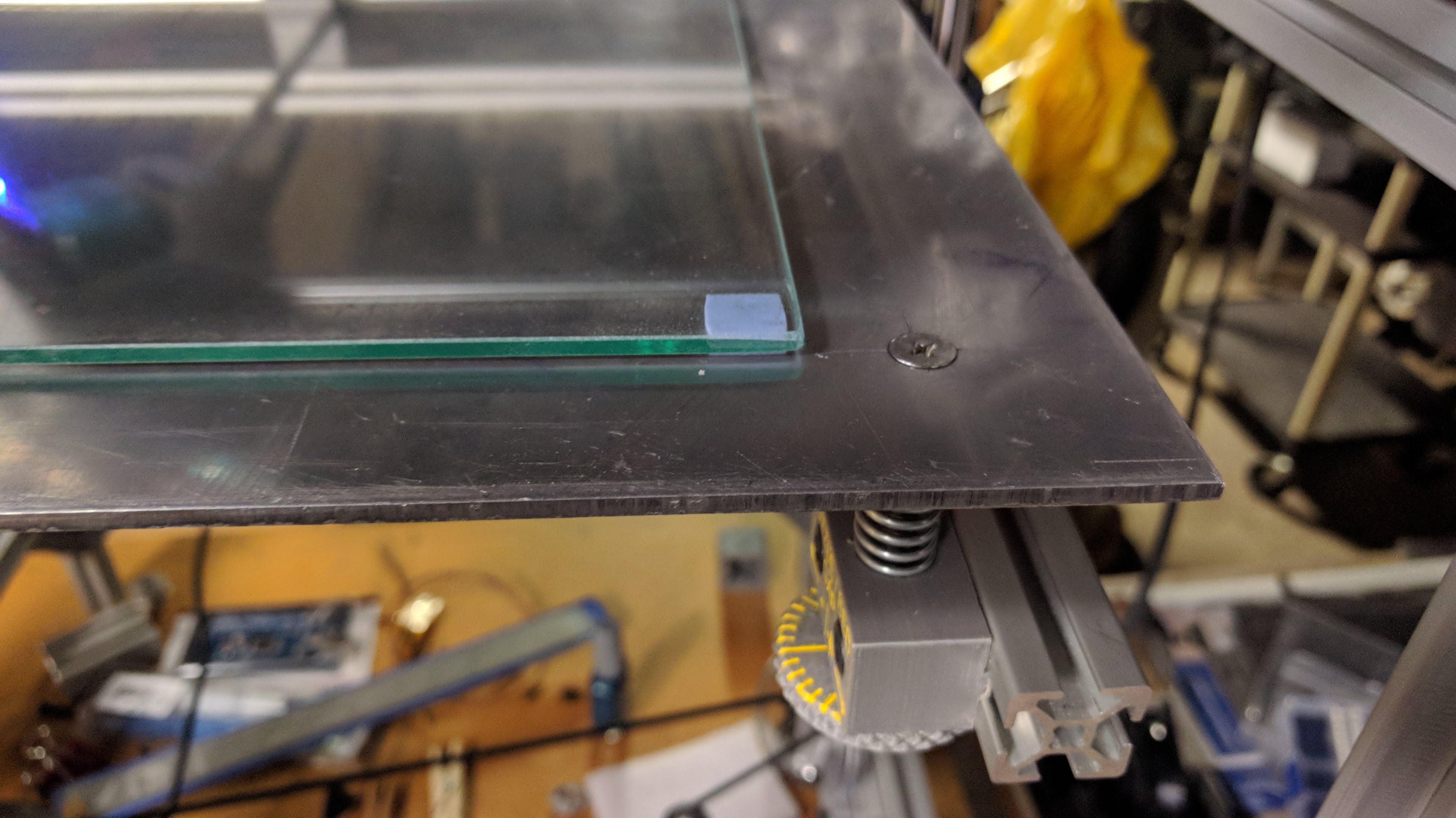
As far as bed flatness… do you run glass on top of your aluminum?
My layer order is aluminum heat spreader, then standard window glass (annealed, not tempered), then PEI stuck to the glass. Aluminum gives good heat uniformity, glass gives the flatness, PEI gives the grip. That combo is my go to for flat and good stick.
For the layer banding there are a few things to check:
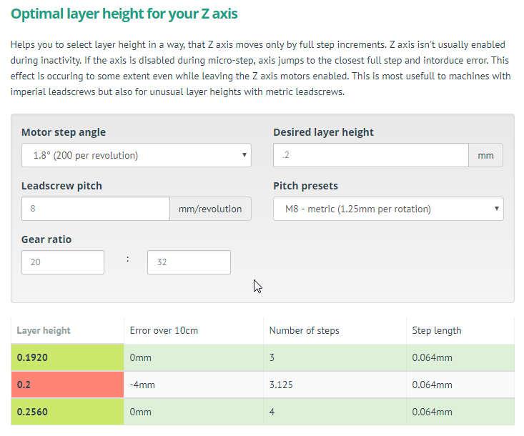
1.) is the layer thickness you are printing a multiple of full steps on the motor?
2,) Look at the light on the SSR running the bed. Is PID tuned properly (a nice on, off, on, off)). Or is it on for a long time, off for a long time, on for a long time. Similarly is it running at too fast a rate (just looks like it is flickering).
3.) If you still have issues, run the bed all the way down, unbolt the lead nuts, and run the bed up and down by hand. Does it move freely, does it feel like the bed wants to move up or down (being pinched because of binding between the constrained z rods). If so you might have some shimming or shaving to do on the Z rod mounts.
Holy information overload!
yes, glass on aluminum bed.i use the silicone thermo pads between as well to gap and stick the glass in place. I need to teak the bed to get the glass to sit better. no pei for me- petg stuck too well for me using it. aquanet on glass only.
i did not think about layer high as it relates to step height. my Z step worked out to 640 steps/mm, so 0.2/(1/640) = 128, so it ends on a full step. i will try with another layer height.
I think its more mechanical at this point. i want to run the breakin codes more and will try running it up and down by hand.
how ‘tight’ are the LMUU10 bearings supposed to be? if you press down on the bed, do you get any flex or slop in the bed displayed?
i have DRV8825’s too. i can switch and tune those and see how they work for comparison.
@Dennis_P aquanet on glass with PETG works great for me as well.
My aluminum plate is as flat as I could get it, but it isn’t perfect.
As a result, when I clamp the glass on one side, it lifts by a few mm on the opposite side. At this point, I just clamp on adjacent sides so as not to crack the glass, but if I could clamp more consistently (flat-er against aluminum), I could level better and get better first layers - large parts or parts on opposite sides of the bed are an issue for me.
I’m intrigued…What is your “silicone thermo pad”? Would it resolve my issue? And where can I find one?
@Benjamin_Liedblad I use 1cm squares of the 1.0mm silicone thermal coupling pad between the glass and the aluminum bed. Its the kind of pad they use between heatsinks and computer chips.
There is no force on the glass to make it conform or keep it in place, only gravity. The stickyness of the pads is enough to keep it from moving side to side. It puts a gap between the glass and the bed, allowing the glass to span across the four corners. The heat from the bed heater radiates to the glass just fine.
Here is the real McCoy-
I use the cheapy ones from eBbay/Amazon, I cant remember which. ~4 for 100 precut squares. On my i3 clone, i have 2 squares at each corner to keep the glass stuck due to the inertia loads of the bed moving and it stays put. Since the bed of the Eustahios is stationary, I only used 4 for now.
I May put a few more in the middle, I just dont know how ‘flat’ my bed is yet.
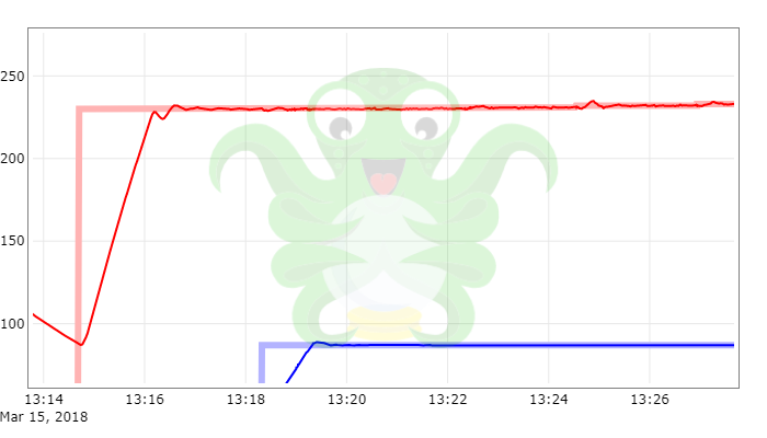
So I figured out that the horizontal artifacts are NOT mechanical in nature, they are temperature change related. I spent my lunch hour watching the printer print after changing to DRV8825’s and tuning them.
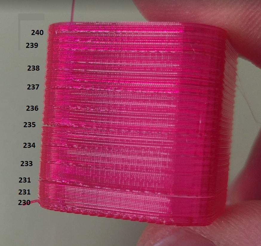
This print was a KISS Slicer Temp Wizard test cube for dialing in the ideal filament print temp. It changes the temp incrementally from bottom to top, instead of printing one of those giant temp towers. The extruded filament seems to change transparency immediately after the start of a loop where it pauses to wait for the extruder to reach the next temperature step increment. I was able to sucessfully repeat the behavior when I changed the number of temp steps over the height.
Now I need to work out the Vref on the drivers and motors. …
@Dennis_P Glad to hear it was a temperature related issue. Have you had a chance to dial in the PID values yet? If you are looking for a reason to dial those in… check out my post from a few years back. On small printers it diesn’t matter as much. On large printers with large beds… thermal deflections can be a real issue.
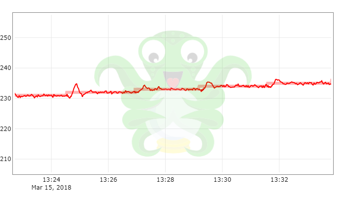
Eating lunch with my printer is becoming a regular thing… I PID tunes with the bed on at 85 for PETG. So now I am running these temp tuning cubes from KISS slicer where it bumps the temps up by 10 steps over the range you specify, and I am noticing these hiccups in the temp tracks in Octoprint.
PID tune again? Tweak it manually? I am looking at the undershot at the start and the hiccup midway through the track.
I am thinking that overall, I wouldn’t print with varying temps like this but the heater output has me thinking.
Anyone know if you can SAFELY goose the output on an ATX power supply? I am wondering if I can bump up the 12V legs a little bit without too much fussing.
When I was starting out on this printer and PETG, I was trying to use high bed temps (like your 85C), but the material seemed to be “cooking” on the glass.
Eventually I found that I had the best results with aquanet and 50C on the bed.
I use 240C for the hot end.
Note: I have not verified that my thermistor readings are accurate.
The Wikipedia article is about the best resource you have for tweaking PID. And the linked GIF below really lets you know which variables to tweak to get certain results to change. It’s under the manual tuning portion of the Wikipedia article.