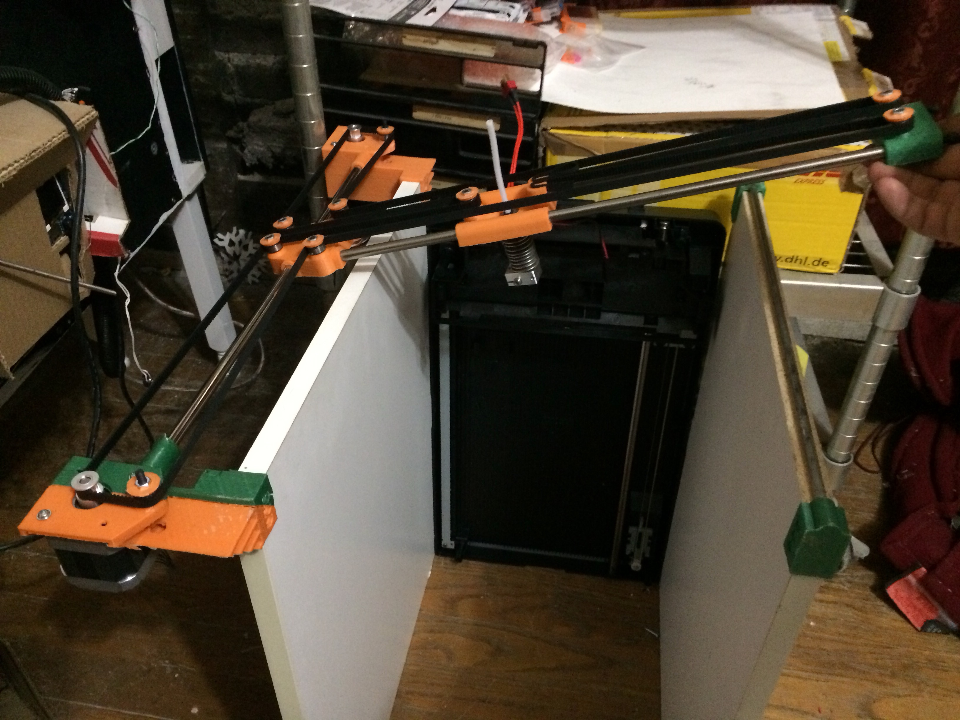
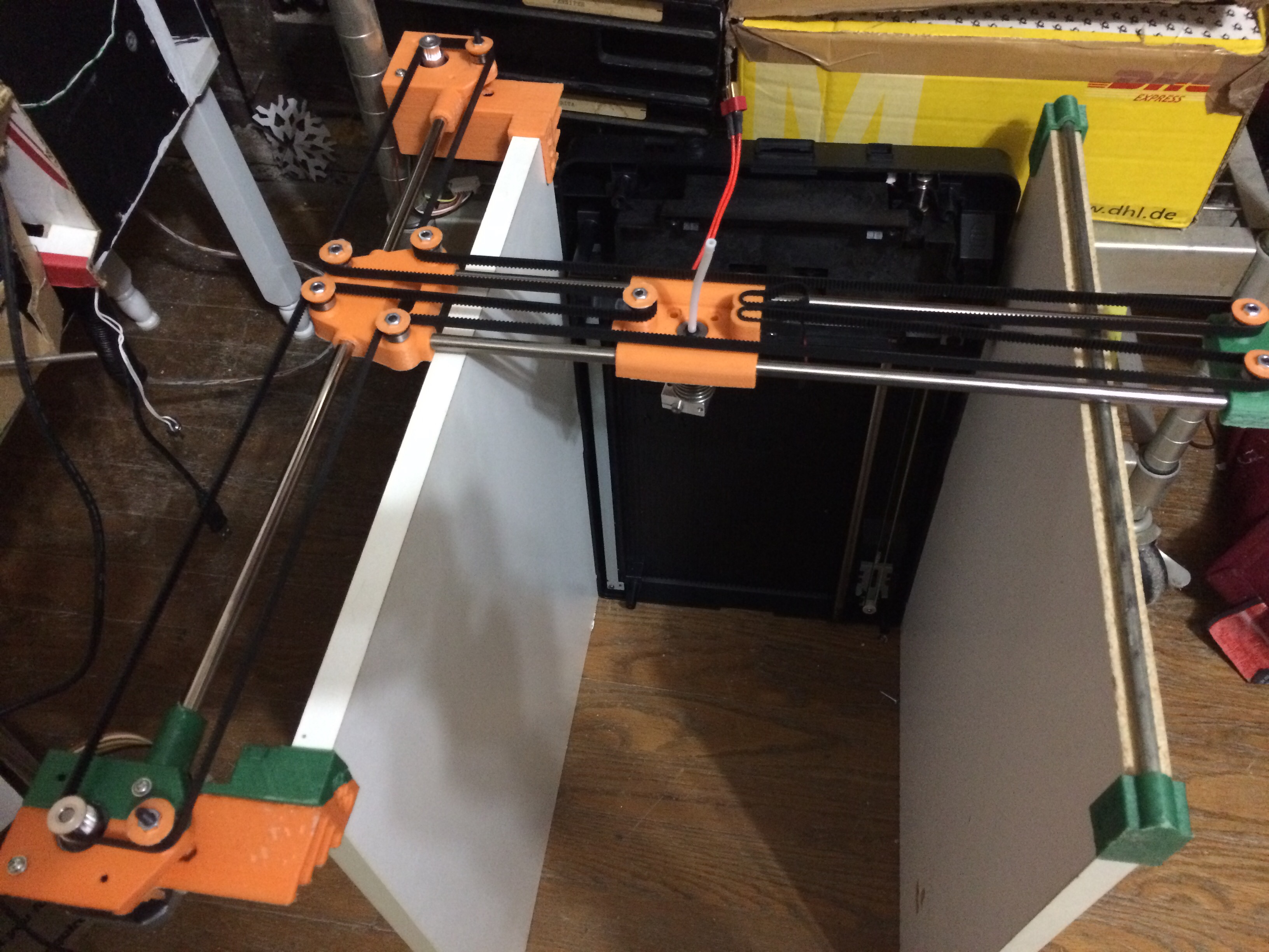
Investigating core-xy / h-bot style drive - but using the arm to carry the opposing belt tension instead of the sides.
Still a week or so away from printing (designing a platform for the old scanner I’m using for Z)
Also experimenting with PLA carriage slides, and rod-on-rod bearing surfaces for the floating side of the arm.
…huh. That’s an interesting one. Pretty sure that’s 100% novel (and I don’t say that often).
If you want to do a cantilevered T gantry only being driven on one side like that, you’re going to need super beefy linear hardware for the Y stage. What you have shown here is going to wobble like crazy during Y acceleration.
Rotational torque on Y is something I’m curious about.
If this doesn’t pan out, I have an alternate design, using two levels of belts, one below and one above the rods, to eliminate rotational torque.
But this one is one bearing cheaper, and 9 bearings was all I had on hand at the moment.
The rods are all recovered from junk printers, as was the scanner Z stage I’m working on.
It’s more of a “what can I make with what I have on hand” kind of a project.
I’m planning on using my 0.8mm tipped E3D on this one, so sloppy tolerances will be fine. It’s for fast big things that I plan to anneal then machine to tolerance.
(Annealing screws with dimensions, but the toughness more than makes up for it if you plan to cut file and drill anyway)
@Ryan_Carlyle That’s one of the alternate belt paths I’ve built in CAD for the “core-T” cantilevered machines we’ve discussed. I wouldn’t build it with linear bearings that require the far end to be supported, but I’ve mocked up small machines that use V-slot or HIWIN-style rails and a short cantilever, and did some test assemblies that suggested that they would be sufficiently rigid at the scale of a micro printer.
@Whosa_whatsis the second one in your post is the first style I considered, but I wanted a wider X for mounting the hot end centrally, and went for that third style.
Great minds think alike, and all that.
The primary reason for the floating end of the X axis arm is that I want to prevent torque on the Y carriage due to even slight stickiness on the far end of the X arm.
That seems pretty long for a single belt, but I might be more concerned about only 90 degrees of belt engagement on the pulleys in combination. But only testing will tell if it’s a problem.
The 90 degree belt engagement on the pulleys bugs me too, that’s less than the 6 teeth minimum Gates recommends. It would be easy to move the Y-end idlers inward a bit (or motors outward) to get up to 120 degrees or so of contact.
Completely agree about the belt engagement. I want to see how bad it is first - firsthand knowledge is always better!
I’m thinking of adding tensioning pulleys near the motor in the next redesign, to take up the slack and increase the engagement from 90 degrees to >180