I'm slowly building a rather different printer on top of the skeleton of my Tronxy X5S

I first tried buying new 3/32" Inch Chrome Steel Bearing Balls G25 that I saw recommended for a different clone MGN12H carriage, just to try the replacement. It looks like my existing cheap set was designed for a different tolerance class, so the G25 3/32" bearing balls were a little bit too large and the rail didn’t run smooth. However, I was pretty sure I had damaged the existing balls for which I had no specs, so no harm in trying a workaround; at worst I’ve spent some time and learned something.

I spent some time stoning the slot in the rail larger to give the new balls more room. I did my best to apply constant pressure from one end of the slot to the other, and started each round with a coarse diamond grit DMT plate and worked down to an arkansas stone, and every 10-20 strokes each on top and bottom of each slot, worked smooth, I cleaned it thoroughly and tried running the carriage. I got bored before I got it as loose as the other rails are now, but it doesn’t hang now. The stiffness is fairly uniform along the length, so I was being careful enough, but I lost patience before it was ready to use in a printer. I’ll keep it around in case I get bored, I guess.

I ordered a set of three of some clone rails with MGN12H carriages that are still not hiwin, but cost more than the original set, and have at least some good reviews. They also come with plugs in the ends to avoid the carriages falling off by accident, and include two extra balls just in case. (The are"free return" so if they don’t run well I can return them without more than loss of some time. I have another use for the two more-or-less working rails anyway.) All three of the new rails slide freely. I’m sure there are uses for which they would be too loose, but they are probably better than the belt I’m using, so they aren’t the weakest link in the chain.

Also, to better tolerate expansion in the gantry, I replaced the drop-in T-nuts holding the gantry on one side with slide-in T-nuts. Of course, I only had M5 slide-in T-nuts handy, so I had to make M3 slide-in T-nuts. I cut a couple 1cm long pieces of 1/8" x 1" mild steel stock, milled them into a T shape, tapped them M3 near one end, and filed them smooth. I put threadlock on the screws, screwed them down tight into the extrusion, then backed them off to just loose enough to move. Now I’m reasonably confident that the gantry can expand as it heats without causing binding.

The first print with these rails and the loose T-nuts to tolerate expansion was the highest quality print I’ve ever done. A few more prints and I’ll have confidence to move forward with starting over on the old printer to rebuild it into something better as well. :slight_smile:

I haven’t done speed tests yet to see what the limits are. Right now I’m printing at 80mm/sec and it looks like I’m being conservative. :crossed_fingers: but so far this is great.

Last night I started a roughly 13-hour print, and woke up in the morning to air-printing — a few cm above what had printed fine, until it suddenly quit extruding. I’m glad it was still trying to print, because I didn’t have to start by assuming that it had clogged, so diagnosis wasn’t so hard. It was made a little harder by the quiet trinamic drivers, though; I didn’t hear the extruder motor turning until I started going through diagnosis and had everything else turned off.

Turned out that the drive gear in the extruder was loose. The set screw in the drive gear had to be so far back that it didn’t engage the flat of the D shaft, so it didn’t take much for it to come loose.

Tonight I wrapped the motor to keep metal dust out, and used a diamond file to extend the D profile closer to the motor. I put threadlock on the set screw, and tightened it as much as I reasonably could, and it’s printing again.

3 Likes

Air-printing again this morning, with the parts nearly complete. This time because the screw holding the idler pressing the filament against the hobbed gear came out. :rage: Two failures from loose screws in a row. Makes me wonder if the real loose screw is in my head! I haven’t used threadlock because I’m still playing with the design, but at some point it’s time to commit.

I’m not ready yet; I need to design a fan mount, and I should probably swap out the titan clone I hacked for the bondtech I already bought, too. I’ve just been hesitant to put the good stuff on while I’m running experiments.

In the past week, the problems I have had were only from

  • I still don’t have a cooling fan
  • I had bad filament that clogged the nozzle, which with XCR3D hotends is an easy fix
  • I knocked the bed off the kinematic mount and didn’t notice. :grimacing:

The new rails are working great. I still haven’t done a speed test, but printing at 100mm/s doesn’t seem to reduce quality, with DEFAULT_ACCELERATION 2000 and JUNCTION_DEVIATION 0.25. The motors are running cool at 1A RMS.

2 Likes

The 30mm cooling fan on the XCR3D hotend is junk. Mark Rehorst noted that his died quickly, and mine did too. Mine quickly developed a bad bearing. I kept it going for a while by dragging a fingernail lightly against the fan as it spun up until the bad bearing seated and it quit whining, but as one would expect that was getting harder and harder to do.

I bought a set of 24V 40mm axial and radial fans, because 24V 30mm fans are hard to come by. After I bought them, Mark Rehorst pointed out that just using a buck converter to supply 12V would let me use a quality 12V 30mm fan, but I decided to first try making an adapter, since I needed to figure out how to also add a print cooling fan anyway.

I designed an adapter that provides an attachment point for a cooling fan and it’s working well so far. The 40mm fan moves lots of air and keeps it cool, and adding part cooling has resolved the normal issue of PLA curling up when printing overhangs and as a result knocking parts off the print bed.

I’ve been printing lately at 80mm/sec maximum, but probably at some point I’ll experiment to see how fast I can push this. I think the limit might be the low thermal mass of the small XCR3D hot end. I’m almost tempted to make a larger block and pid tune again, but probably not tempted enough to actually do it. Getting higher quality at 100mm/s on this printer than I did at 30mm/s on the “bed flinger” makes me happy already. :slight_smile:

2 Likes

I have just finished tuning up 3 of my Di3 printers. Rebuilt all the hotends, rersquared the gantries, oiled bearings, replaced build plate surfaces, and recalibrated extrusion rates, PID tuning on the beds and extruders. Now I need to figure out why my PrintrBot simple Pro performs correctly on my office PC, but using the identical settings on my print farm PC it wants to drive the hot end into the bed. Temporary fix is to have the printer on a rolling cart and wheeling it into the office. Not a viable long term solution by any stretch of the imagination. I have pulled apart my large format printer and am redesigning it, as I was not happy with my original design. Always something to do with these printers. Oh, and did I mention I am also designing a portable small foot print printer that will fold down and fit into a pelican style hard case for transport
?

2 Likes

Something about the print farm PC must be confusing the induction sensor, then? I fixed a simple metal for a friend, whose induction sensor wasn’t working on 5V, but by jumping it to the 3.3V bus it worked fine.

Now that this rebuilt printer is better in every respect than the bed flinger, I’ve been challenging myself to design a new bed-flinger that I can build as much as possible with parts I already have lying around. So far the only part I havehad to order was a short closed-loop GT2 belt, and I chose also to buy some optical limit switches even though I have microswitches available. It’s a design that I haven’t seen anywhere else, so it’s probably a terrible design. But if I take that on, that will be a different topic! This one’s long enough. :grin:

1 Like

I might just pull the Simple Pro apart and install a spare Cohesion3D mini board (smoothie) and call it a day. I am not a fan of the TinyG board that is in the Simple Pro, and the LCD is useless without the web app for it. I have an MKS LCD touch screen that could replace that LCD easily and give me back some headless functionality.

2 Likes

Back when I started this project, I kept an eye out for 330mm square PEI because I have a 330x330mm (nominal 13") bed, whereas a lot of similar printers have a 300x300mm (nominal 12") bed instead. I finally found a sheet of 13"x13"x 0.8mm PEI listed on amazon and bought it, and set it aside for when I was ready to mount it.

It didn’t occur to me to measure it.

Today I wanted to start printing ABS, and overall the printer was working well, so I went to install the permanent bed surface.

It was labeled 13"x13".

It measured 12"x12".

Return window closed on May 22, 2018

And now I understand why that particular item hasn’t been available for a long time.

So I’m back to printing on glass for the moment, and considering my options.

I guess I could cut the undersized piece down to size for the smaller bed for the gantry cantilevered design I’m considering if I do decide make that and not just think about it.

1 Like

One of the interesting effects of the 750W bed on this printer is that the lights flicker in the room while I’m printing. I think they are dimming LEDs that are interpreting the slight changes in voltage as the SSR modulates power to the bed as a dimming signal, rather than really running low on power.

Maybe I’m more easily annoyed by it now that I’m putting up with ABS smell as I print. It does take longer to heat up to 115⁰C than it did to heat to 55-75 for PLA or PETG. But it’s great to have a printer that can actually hold that bed temperature!

1 Like

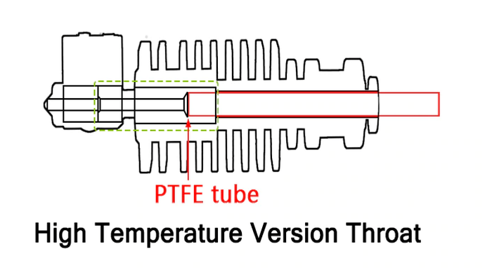
I’m using the XCR3D XCR-BP6 high temperature hot end. I had inserted PTFE guide tube as far as I could into the top of the hotend. I kept having problems with jamming, though. I finally realized that the PTFE guide tube that shipped with the unit was slightly narrower in OD than the PTFE guide tube I already had on hand, and switched to using the right guide tube. Now I notice this diagram, and it finally makes sense. It hadn’t made sense when I was using the wrong tube.

Don’t be like me, use the right OD guide tube.

I believe this is why I’ve had trouble printing about 100mm/sec when this should be able to go a lot faster. I had inconsistent under-extrusion and jamming when I tried to go faster. I’ll have to try again now. It could make a big difference in how fast I can print face shield frames.

My hot end shipped before they started including matching silicon socks. I have wrapped the heater block in kaptan tape to insulate it for now; it makes a difference. I also used kaptan tape to keep hotend cooling fan flow away from the heater block. I have ordered some of the XCR3D BP6 socks, so some day they will arrive from China. Also, I should re-do the PID tuning with the hot end wrapped; I’m seeing some poorly-damped large temperature oscillations now that it’s insulated.

Update: Printing at 160mm/s is now fine, no evidence of a problem. I’ll try cranking it up even faster to make more frames. I do need to take a break to PID autotune with the new fan and kaptan; twice now it’s sat there for more than an hour overshooting in both directions trying to get to even heat. I also should increase PID_FUNCTIONAL_RANGE from 10 to 15 because oscillating overshoot can result from too narrow a PID range.

Update 2: I ended up having to change PID_FUNCTIONAL_RANGE to 25 and MAX_OVERSHOOT_PID_AUTOTUNE to 50 (from 30) in order to successfully run a pid tune cycle. Then to avoid waiting too long to start a print, I set TEMP_WINDOW to 2 and TEMP_HYSTERESIS to 5. Maybe I can put those two back after I build the enclosure.

Also, because I have the high-temperature hotend, I changed HEATER_0_MAXTEMP to 315. With this I’ve been printing PETG at an astounding-to-me 280⁰ — though with slower speeds than ABS, now that the family has made it clear that ABS isn’t getting printed without enclosure and air filtering. :slight_smile:

1 Like

Finally found a source for 13" sheets of PEI, as well as other sizes including custom:

Of course this is after ordering a spring steel bed from China, and I haven’t decided whether to order this too, but at $20 it’s less than I paid for the falsely-advertised sheet on Amazon.

2 Likes

I bought dual-layer polycarbonate greenhouse panels to make an enclosure. Of course, after I bought the panel, I discovered that I don’t know how to cut it. I’m hoping repeated scoring with a utility knife works, because I don’t want to next buy a new blade for my circular saw… Also, my plans don’t involve accounting for any kerf from a saw blade, because of course I need to make things difficult for myself. :roll_eyes:

1 Like

That polycarbonate isn’t very thick. I scored it as accurately as I could, then used a rocking motion with the utility knife to cut through the top surface and most of the way through the corrugations, then bent the panels slightly to open the cut, then finished the cut with light passes with the utility knife in the opened slot.

1 Like

The spring-steel bed arrived from China. It wasn’t bent, and it was well packed.

It shipped with a full-size sheet magnet, like a giant refrigerator magnet, to stick to the bed and print on top of, which I didn’t understand would be included with the order. It seems to me the sheet magnet would be unlikely to be a good heat conductor, and I have no reason to think it will take ~130⁰C well when I’m printing higher-temperature plastics.

I thought that most people with magnetic sheets were embedding high-temperature magnets in the bed to hold it in place. Am I missing something? I have never bought a kit that came with a magnetic bed…

… The seller said that the magnetic sheet is good to 130⁰C, so I tried installing it on the bed. I tried printing PETG with an 80⁰C bed, and it printed fine. The adhesion was so strong that it tore out part of the PETG from the print and it was difficult to remove from the bed. Now I’m as torn as the part on whether this was a good idea! :slight_smile:

I’m starting to think that I should have two beds for this printer. If I were doing it over again, I would use 3/8" or 8mm rather than 1/4" cast plate for a 330x330 bed. :thinking: (Or: maybe not, perhaps as thin as reasonably possible reduces potential for bowing from uneven heating.)

After testing, I note that using windex as a print release agent works well for PETG on this surface. I’ve had less success printing PLA on it. I’ve cleaned it with IPA, tried both sides, tried different temperatures, and nothing is sticking well.

I guess I should have tried hairspray for PLA; it works for me so well on glass, why not on PEI?

For my own later reference, the same spring-steel bed without the magnetic sheet, as a replacement when this wears out.

I haven’t yet tried PLA on it since my new can of hairspray arrived, but I’ve decided I like hairspray on the PEI surface for PETG, as long as I refresh it for every print.

I bought 2 additional steel sheets linked above without the magnetic back. Ordered July 22, arrived today. Very well packed, four layers of cardboard and corner protectors on all four corners, no visible defects. I was expecting months, so this was a pleasant surprise.

Hairspray on PEI is working OK for PLA but I’ve still had some adhesion failures, just not as bad as it was before. Still thinking about adding an offset for printing tricky PLA parts on glass instead.

2 Likes

I use dollar store stick glue. Cleans up easily and never had failure. In fact can be a bear to release when fresh!

I quit using glue on glass a long time ago, but I still have the sticks by the printer. Have you used glue stick with a PEI bed?

I only use glass because with everything else I’ve used I never had great luck with. I also like how the base comes out when using glass.