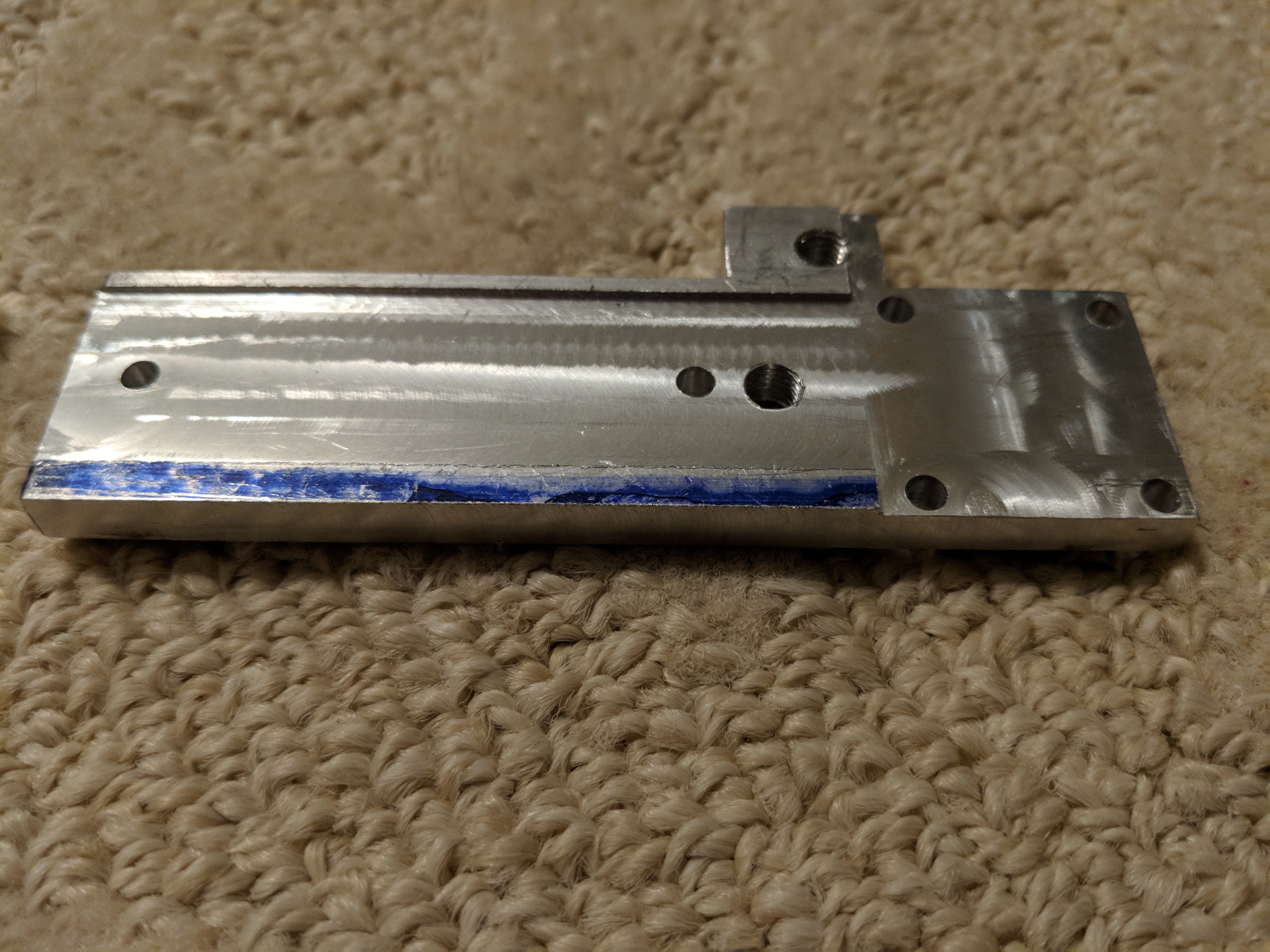
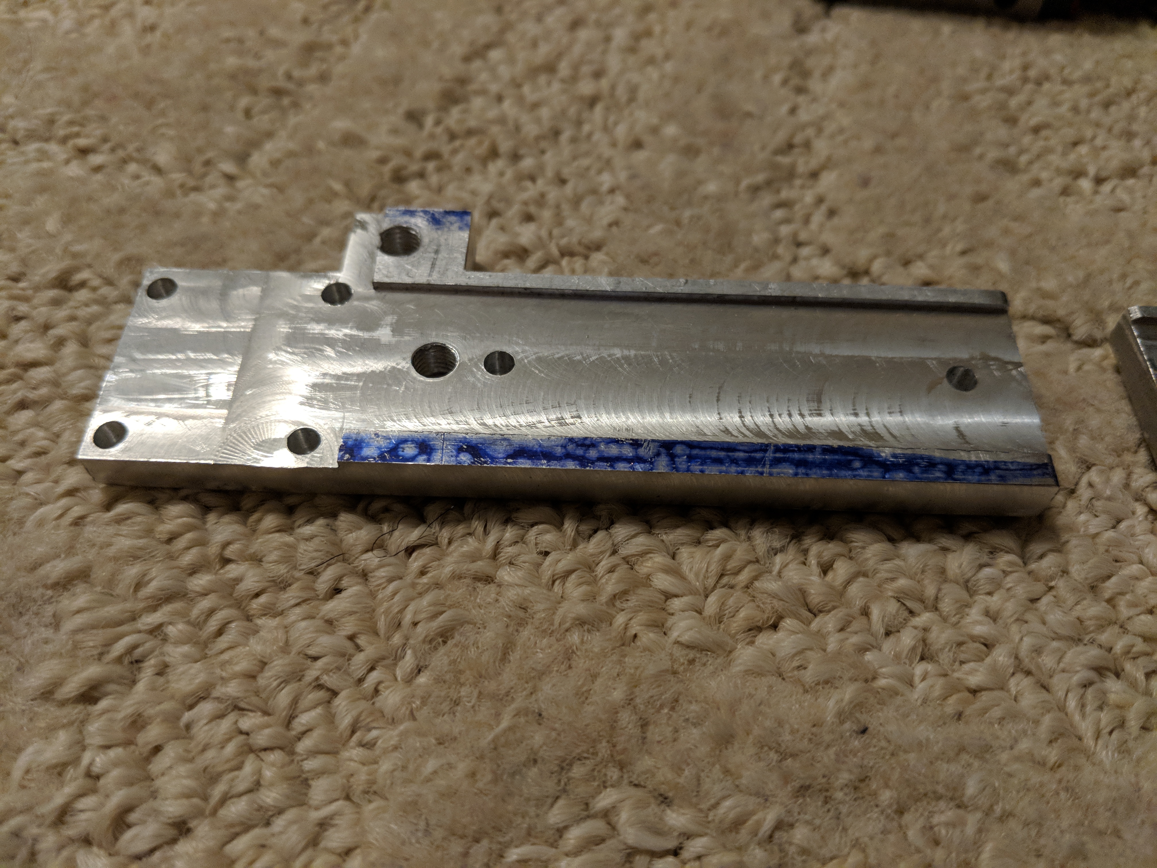
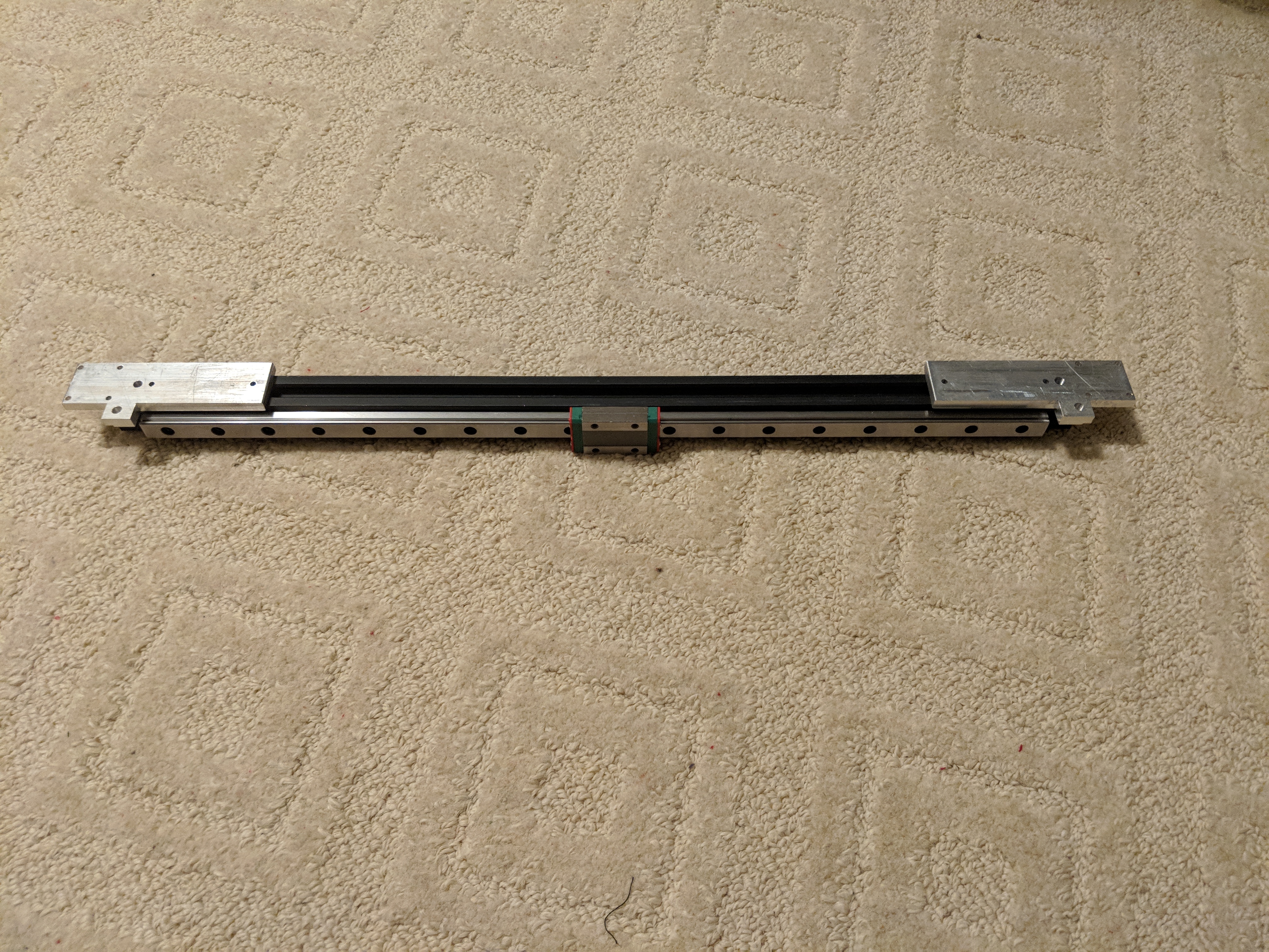
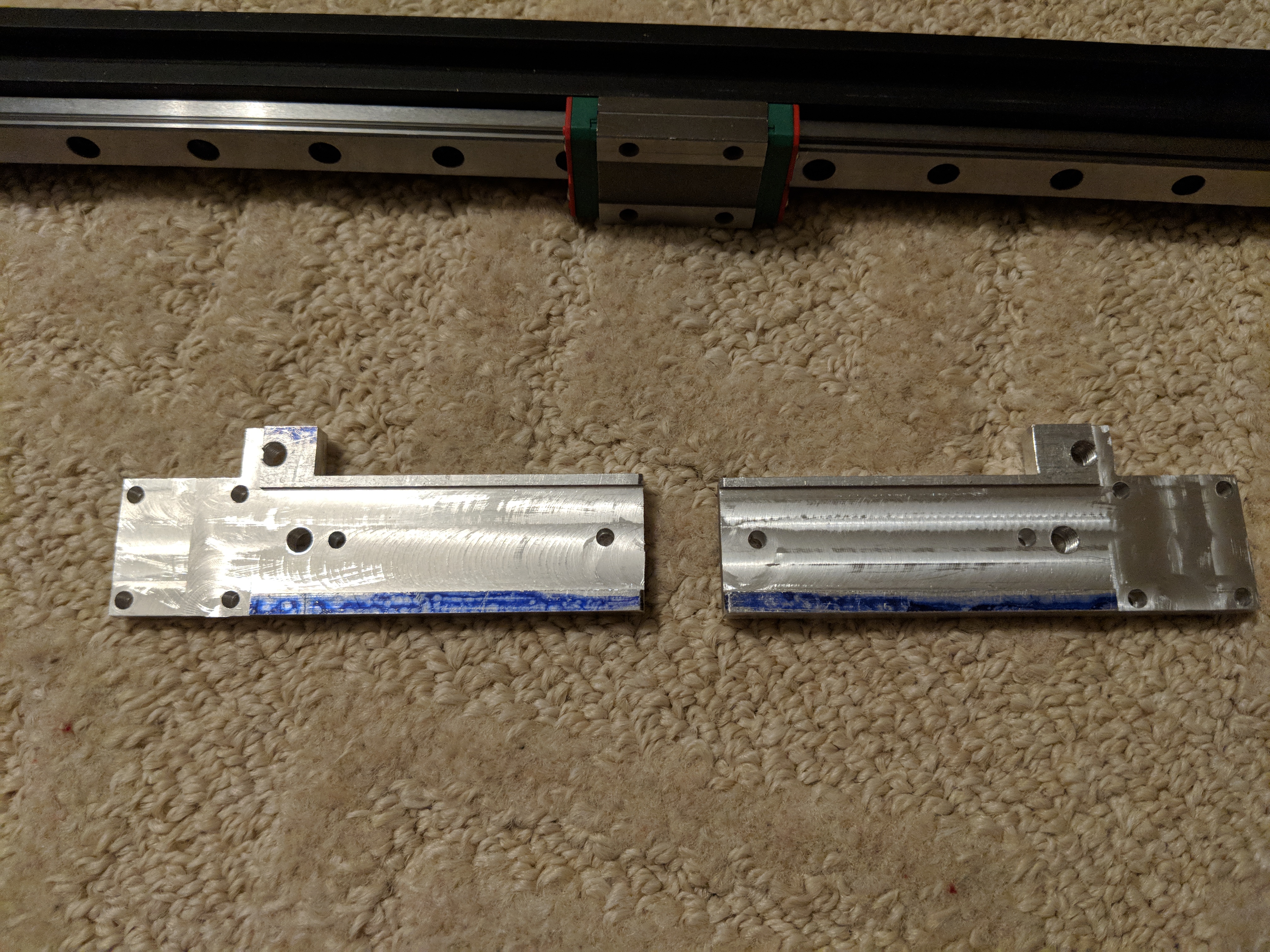
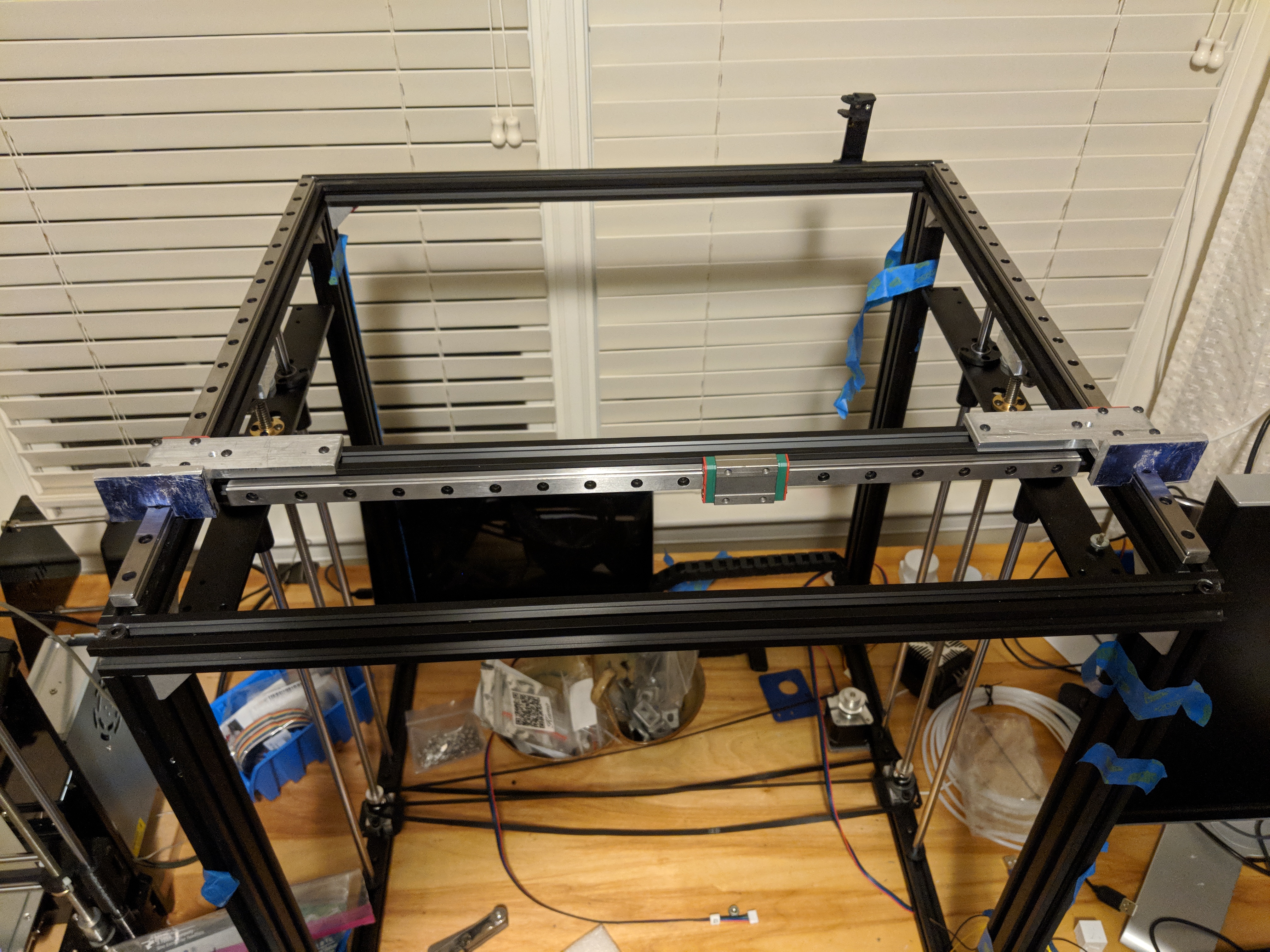
I’m slowly building a rather different printer on top of the skeleton of my Tronxy X5S. Previously I replaced the Z mechanism with a single motor and continuous belt driving synchronized single-start 2mm lead threaded rod, and milled alignment jigs to mount linear rail to the top of the Y axis and front of the X axis extrusion. Today I finished milling a set of gantry mounting plates out of 1/4" (6.35mm) aluminum plate to attach the X gantry extrusion to the Y linear trucks.
My prototypes last week were a little sloppy and tended to bind. While milling these new mounting plates, I worked to or even beyond the 0.01mm precision of the DROs. That long slot down the middle is for 2020 extrusion to fit into. When I had milled it 20.00mm wide according to my DROs, the 2020 was too tight a fit. I moved the bed slightly, but not enough to register on the DROs, and could hear that the mill was just barely touching as I ran it down the part, making the slot less than 0.01mm wider—but making the slot a perfect fit for the 2020 extrusion; a snug but easy fit, with no wobble.
Unlike my prototypes, I put the center drills in collets to start the holes, and now they are sufficiently precise that the whole mechanism stays very square. It no longer binds while moving in Y as the prototypes did.
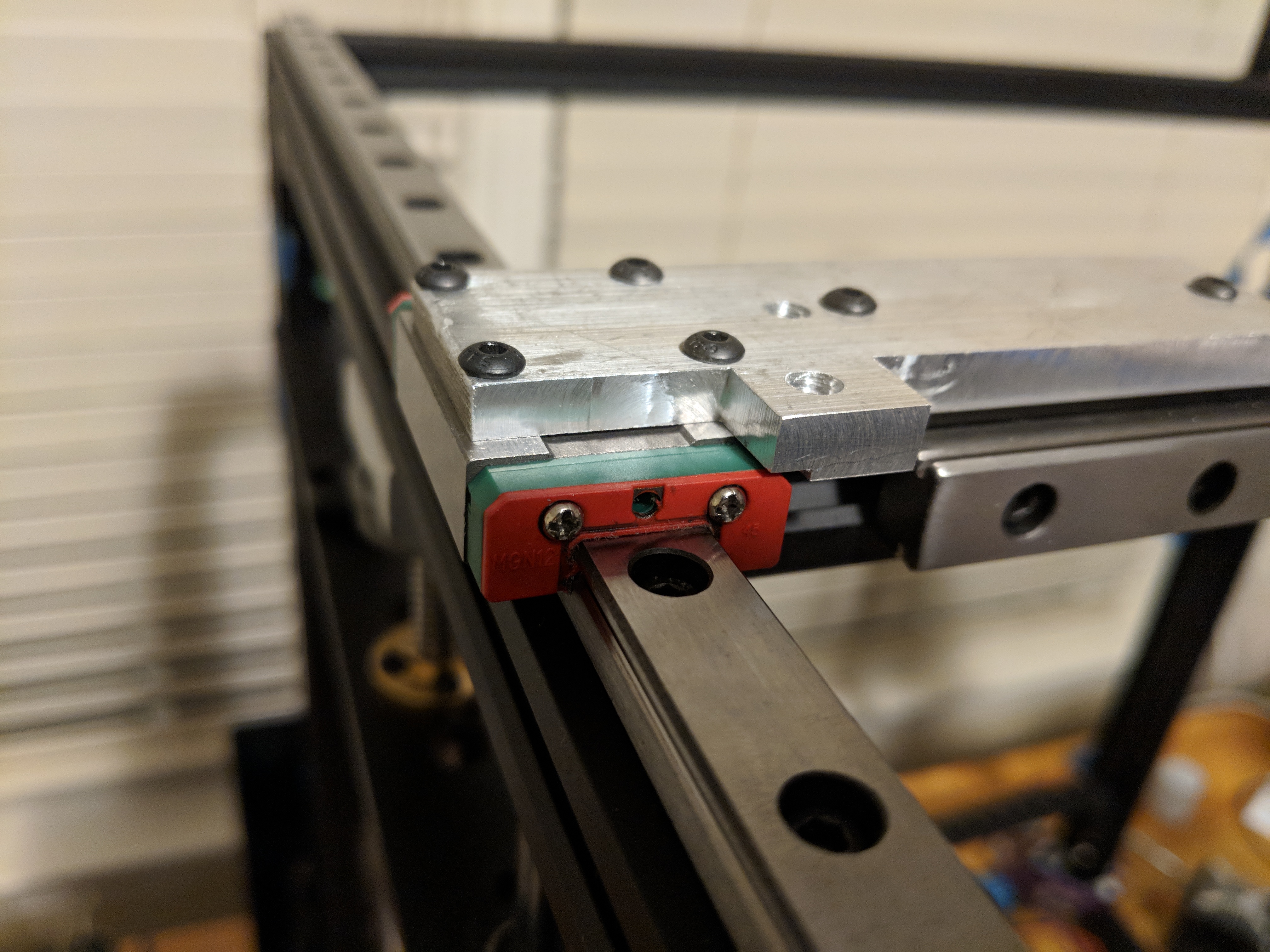
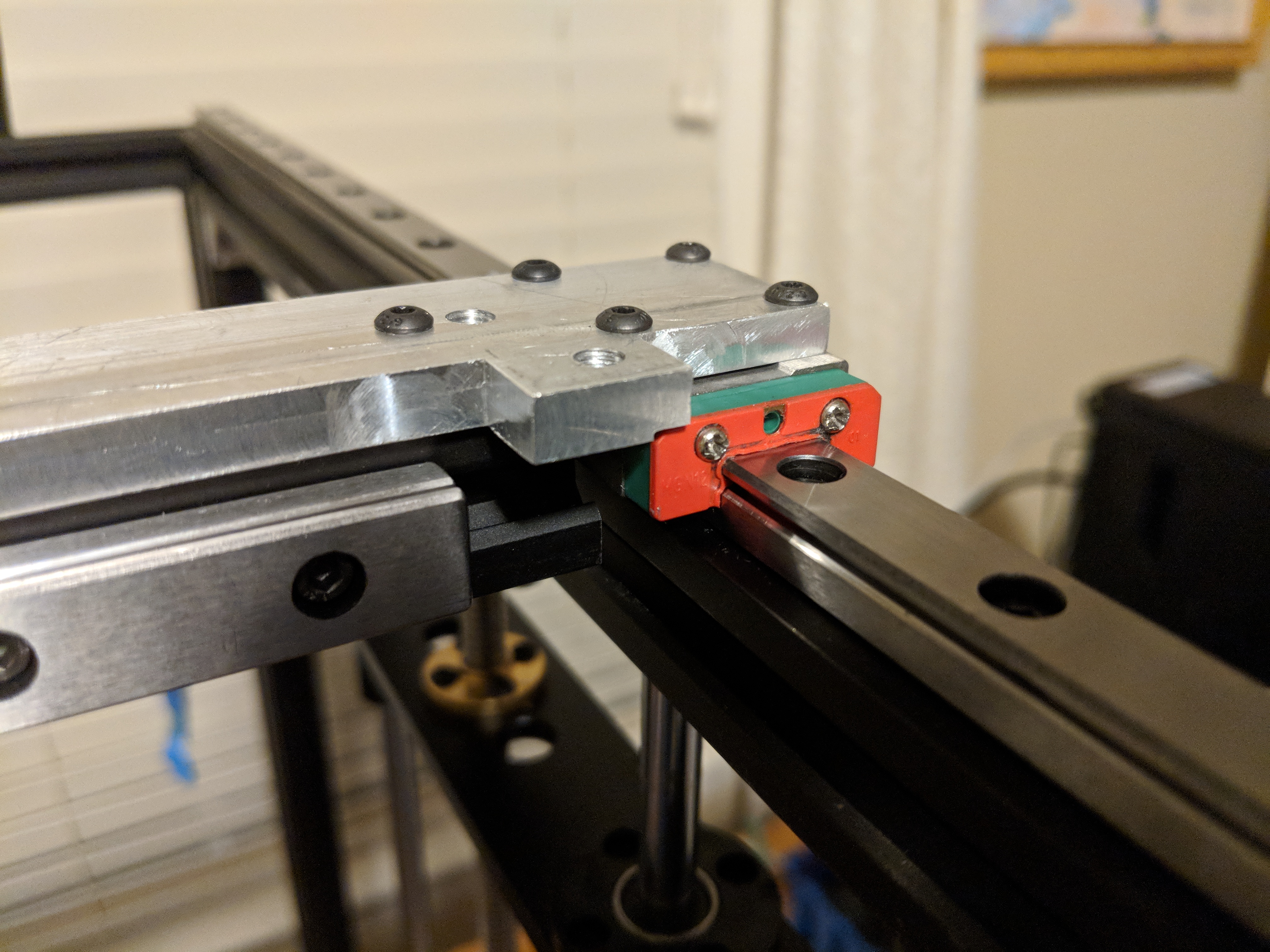
The smaller holes are 3mm holes for M3 machine screws to go through into T-nuts (extrusion) or threaded mounting holes (Y linear trucks). The larger holes are threaded M5 into which to screw M5 bolts with 635ZZ bearings (for the back side of the belt) and 20 tooth idler gt2 belt pulleys (for the front side of the belt). They are aligned to attach to the back of a plate screwed to the X linear truck. I plan to lock them in place with an M5 nut on top of the plate, and hold the idlers at the right height with 5mm ID bushings.
The aluminum is from scrapyard special 100mm x 100mm x 1/4" plate. “Reuse” comes before “Recycle” remember!
The blue things on the front of the Y rails are the alignment jigs I used for mounting the linear rail on the extrusion. I also used them to line up the X gantry assembly square while screwing it together, which was why they show up in these pictures. The blue color is prussian blue from scratching cut marks in the surface to guide my work.
We do use this system daily to build hydrostatic linear turning machines, with a 0.001mm precision. Do keep in mind that short axis movement on linear system, creates a deveation on the area used the most. Use a light weighted lubricant to preserve and prolong the durability of both rails and bearing carriage. Overall , looks great and nice concept. Keep us posted friend.
@Kevon_Daines thank you! This isn’t genuine hiwin rail, and I can tell. I wanted to prove out the concept with less expensive components, so when these wear out (despite lubrication, thanks for the reminder), if I’m happy with the overall design I’ll probably splurge on the real thing.
I was incautious while assembling the rail to the frame a few weeks ago and knocked one truck off, spilling some bearings. I’m not sure I found every spilled bearing to return to the races, though I found at least most. I expect this carelessness to come back to bite me; if it does I’ll just use it as excuse for update
@mcdanlj That is most inconvenient having lost a few bearings. Linear motion requires a perfectly balanced axis.
If my knowledge does not elude me, each bearing housing is milled ,turned and fine finished grinded into tolerance.
A specific diameter of bearings is then used according to surface precision readout. In the event of loosing bearings , there is a 20 to 80% chance that these cant be replaced at your local hardware store.
If possible , try to measure the bearing diameter with an digital mm caliper. Having reserved bearings can’t hurt.
There is a 100% chance I can’t replace the bearings from my local hardware store. If I were measuring them for replacement it would be with a micrometer not caliper; caliper is not nearly sufficiently precise.
I don’t have a count of how many bearings are supposed to be there, and I can’t easily count the bearings in the blind part of the recirculating races anyway. The bearing races are intentionally underpacked, so a small gap is expected. What’s more likely to cause wear is that I used a magnet to help pull them out of the carpet, and residual magnetism may cause the bearings to rub.
The 450mm MGN12H sets I bought were $23 each. There’s a limit to how much it’s worth investing in them when they aren’t perfectly smooth even unloaded. But it looks like genuine hiwin would be about $100 each for a set, and I’m glad I didn’t make that mistake with the real (expensive) thing.
@Kevon_Daines You can run them with a few bearing balls missing, and it’s not a huge deal because 3D printer loads and speeds are pretty light compared to the bearing ratings. Not ideal but it works. Obviously the more you lose the more likely you are to have problems though.
@mcdanlj Understood, but based on the tolerance mentioned a 0.01 mm digital precision caliper will be sufficient.
Indeed , if the tolerance were to require a higher precision (ex. 0.001μ) then a micrometer would be needed.
I have never seen anyone with this concept before. Which probably raises the question why this endeavour. I should undoubtedly look further to more of this project.
@Ryan_Carlyle it will likely work nonetheless, but regretfully ant the end on the missing bearings there will be a print error probably. Not ideal but works.
@Kevon_Daines these linear blocks have something like 20-30 bearings in contact on each side of the rail at any given time. It’s not like a rotary ball bearing where only 2-4 are loaded at a time. The other balls will carry the load without deflecting any measurable amount. In fact, in cheap rails with slightly inconsistent ball sizes, you often get uneven ball loading and only the larger balls carry load at all. I probably wouldn’t worry about it until 5-10% of the balls are missing.
@Kevon_Daines the tolerances I mentioned were for the parts I was machining and do not apply to the linear rail system. I don’t have spec sheets for the knock-off rail I bought, so I don’t know their specified tolerances or bearing sizes. As I say, if/when it is a problem, if the system is otherwise working well, an upgrade to real hiwin should address that problem.
I slowed down playing with this project as I learned machining (see the parts above I machined for the project) and then just as I was about to pick it up again, Google announced the Google+ shutdown and I spent a lot of my spare time working instead of moving content to MakerForums and improving this site. Every time I walked past the half-empty skeleton of the X5S, it mocked me. Then the junk “bed-flinger” hictop that got me into this whole 3d printing experiment really started to wear out, so I finally started work again.
I made a few mistakes, but so far I have a SKR Mini E3 V1.2 and TFT35-E3 connected to it, a 750W 120V SSR-switched and TCO-protected keenovo heater heating up a 1/4" / 6.25mm cast aluminum bed, a 24V DC supply, and a single Z motor running single-start lead screw with a timing belt keeping both sides in sync, as well as the linear rail I started the post with. It bears almost no resemblance to the X5S I started with, just the frame and some parts of the Z stage remain.
It’s spitting plastic again for the first time today. I have a lot more to do. I don’t even have a cooling fan mounted, and I’m sick of the bowden feed and will replace with direct feed. It turns out that the cooling fan on the dying bed-flinging printer wasn’t running anyway, so that’s not first priority here; switching out the bowden for direct drive is the first thing I need to do.
I’m currently printing on glass on top of the aluminum bed while I decide whether to install the thick PEI sheet I bought earlier, or get a PEI-coated steel sheet instead:
I bought the hollow-core polycarbonate sheets that Mark Rehorst recommends for an enclosure, but I’ll wait to build that because how high I make it depends on what I do to ditch the bowden for direct drive.
I converted from bowden to direct drive. I had purchased a cheap clone titan extruder that Mark Rehorst had mentioned, and modified it to add a filament guide as he suggested. It’s temporary while I decide how I want to mount the bondtech I got.
I did have problems with the extruder not working. It would sometimes extrude a few mm of filament and then make noise and the motor would jitter noisily. I carefully went through every possibility I could think of, swapping out stepper motors, wiring harnesses, stepper controllers. I finally discovered that there were two physical problems: the set screw on the drive gear was very slightly interfering with the driven gear (solved by moving the drive gear about 1 mm further down the stepper shaft), and the screw providing the axle for the driven gear cause binding when it was too tight. Simple in retrospect, but carefully trying one thing at a time took hours of debugging.
I picked a random recent model to do a test print, and the quality is so much better than the “bed-flinger” ever was! I have a lot more I can do to improve here, but this is so much of an improvement I’m about ready to tear apart the bed-flinger and make something better out of it; I just didn’t want to be without an at least somewhat working printer if I could easily avoid it.
But I should design and print a fan shroud for the newly-rebuilt printer before too long.
By far the loudest part of the printer is the 30mm fan that came with the hotend. Now I discover that Noctua don’t make a 30mm fan, so I need to print a 40mm to 30mm duct/adapter as well as a cooling fan shroud.
Also, I found that I had an idler pulley binding sometimes, which resulted in some spaghetti printing. The beautiful print I started last night turned into spaghetti after about 28mm of Z. I removed a shim washer that seems to have been responsible for the binding I saw.
Sadly, metal from the binding idlers got into the MGN12H carriage and… now the carriage binds. So I guess I order new carriages and see whether they run smooth on the existing rails after a deep cleaning.