I’m looking for information on the mks adapter. I am wondering about the chip and it’s function. I could not find any real information on it other than it’s typical use is to add a bigger motor to a control board.
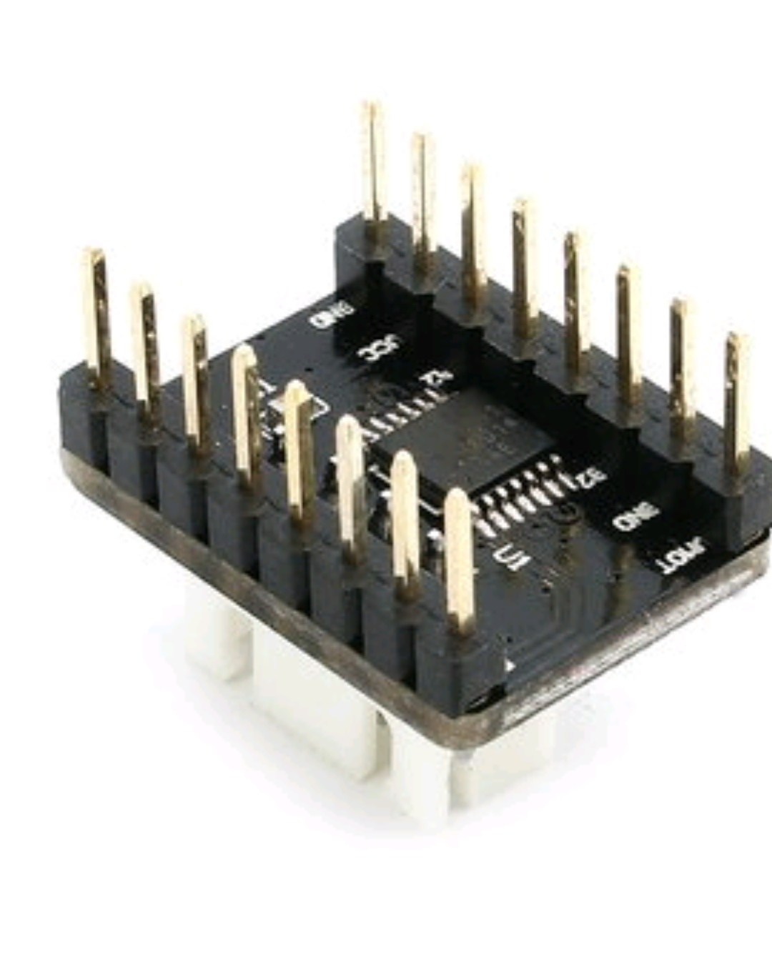
It’s most likely just a simple buffer chip. Standard Arduino/Microcontroller outputs by themselves have a low current rating, which may not reliably drive some of the larger stepper drivers, especially if there is some distance between the electronics and the driver. The buffer chip can provide a lot more current which will give the drivers a clean signal to work with.
@Stuart_Young thanks Stuart. That is what I was hoping to hear. I’m working on an expantion board to add control more extruders and I’ve built a couple of adapter boards like these, but they are simply a wired pass through board. They work but I’m hoping these will work so I don’t have to make my own.
looking on bangood’s description of it in broken english, it’s an optoisolator.
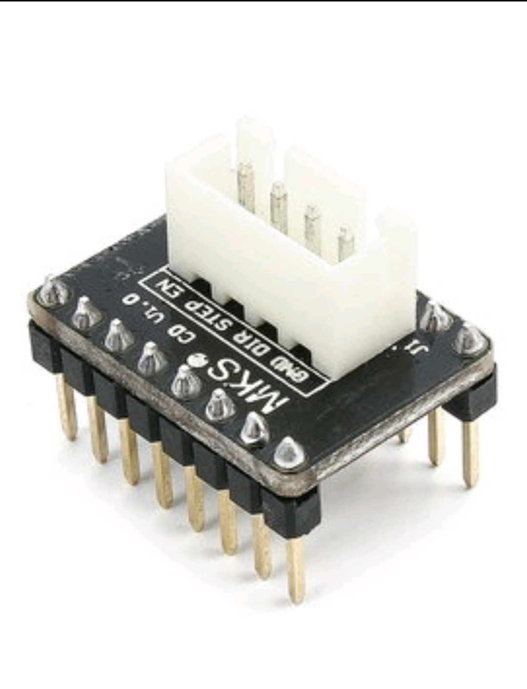
“MKS CD expansion board can adjust the flow control signal, to avoid motor drive with optical isolation generate press on main IC, therefore, Ramps1.4, MKS Gen and other main board with five large motor drive can operate completely without pressure.”
Hmmm. I have been making something similar for a while, no isolation on mine. Any decent driver already optoisolates on its end and no issues here. I also find that the screw terminals are more friendly than a header.
@Matt_Barth Do you have a link to one of the listings for that adapter?
I think it might be a logic buffer. I might willing to buy to see. Some external drivers really do need it.
FWIW: It’ll either be an Opto isolator or possibly just a hex buffer/driver like the 74HC125 or 74HC126. They’re quad buffers with tri-state outputs (not really needed), but they’re simple, cheap and they’d most likely do the job. If it’s an opto, then it’s basically doing the same function, as the opto will be able to drive higher currents than standard microcontroller outputs.
The other thing they might be handling is level shifting, as in some cases it’s possible the electronics could be using 3.3v signals (eg: RADDS, RAMPS-FD, etc), and the driver (5v). Opto’s would probably be better at this than buffers, but not impossible.
Level shifting with logic buffers is trivial. I do exactly this on my 3.3V smoothieboards because my external drivers needed more current than the board could reliably sink.
@Jeff_DeMaagd Depends on the actual driver chip they’re using, and how they’re hooking it up mainly. That said, there’s the question of where they’d get the 5V from, since the voltage being fed to the drivers would be 3.3v. If you’re lucky, you might be able to pull it back from the external stepper driver, but that depends on the driver (not all have a 5v output line).
A