I’m going to hook up my mA gauge when I get off today, am I right in thinking it hooks up to the anode side of the tube…no documentation came with it…anyone here know?
see if that helps Scott
Do you not already already have an analog one? If so, should be plug-n-play.
The negative goes to ground and the positive goes to the cathode of the tube. That way it’s kept at ground potential. If you hook it to the anode side, it will be at +15kv and that will create a safety and arcing problem.
In 99% of the cases a current meter can go anywhere in the circuit (the current is the same throughout the circuit), EXCEPT in this case when measuring high voltage.
@Scott_Marshall …I get confused on which end is which…the beam comes out of the cathode side and not the anode side…I was going in the right direction just had my terminology wrong…lol
I have a hard time also
The Anode is positive, the thick high-voltage wire. Red on most set-ups. it’s the one that comes out of the back of the power supply. It will go directly from the highvolt out on the power supply to the tube, and is the one you want to silicone. It’s @ 15kv over the rest of the machine.
The Cathode (Ground or negative) is just a regular machine tool wire (since it’s tied to ground thru the Ma meter, it’s only a few volts above ground), and goes back to ground thru the Ma meter. It connects to the positive side (because it’s MORE positive than chassis (actual) ground. Then the Ma meter goes directly to the ground connection at the power supply.
Sorry if it’s a confusing description, the simple answer is the big red wire is the high voltage one. (edit - Positive (anode) is the beam end)
Edit:
I checked. I was wrong, the Anode is the Business end, where the beam comes out.
@Scott_Marshall …ok so I was right the first time?..lol…
Cathode is high voltage…anode is where I’ll be hooking up the meter…the anode goes back into the power supply on my unit…maybe it’s grounded in the power supply.
@Scott_Thorne Glad you got it working, but your description is wrong. Cathode is the ground side, which is where you want the meter.
The Ma meter should be in the Cathode circuit, which is the negative or ground side of the tube. Between the cathode (non-light emitting end) and the ground wire on the power supply (usually white or black)
Otherwise the meter is going to to be “hot” with high voltage. I think you must have connected it properly or you would probably have arcing right thru the plywood enclosure and most probably blown the meter.
Just want to make sure, because it IS possible for a Ma meter to work in the high side of the circuit, if everything is well insulated. If you do have it wired into the high voltage side of the circuit, and it’s working, I’d be concerned that someday you could get a shock from the meter or it’s attached wiring. It has lethal potential, the power supply can easily kill.
Anode = Positive = Emitting end = Red wire (usually) Insulated with boot and silicone seal. There should be NO other connection here - straight from PS to tube.
Cathode = Negative = Ground end (non-emitting) = White or Black wire (usually) = Ma meter “+” terminal
Sorry to beat this to death, but I wouldn’t want you or another reader to do it wrong and get zapped.
Scott
Maybe the left-right is wrong, I was going by a photo I found online. Sorry for adding to the confusion.
Haven’t looked at mine
I did a quick CAD drawing, but can’t figure out how to post it.
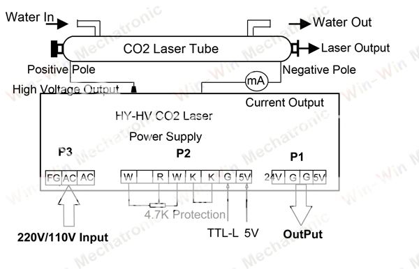
Found a good drawing online, link: