Okay, so I’m making good progress on Grbl-Esp32, with help have successfully compiled and run code on a Wemos R1 D32 with attached cnc shield v3.
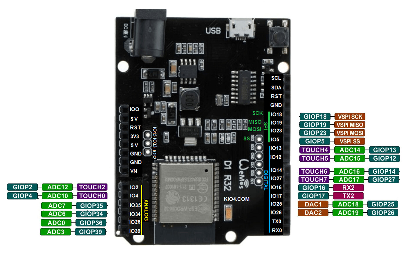
However, I am totally in the dark as to which gpio pin referenced in the Machine.h file corresponds to the pin on the shield.
The cpumap.h file no longer contains the info.
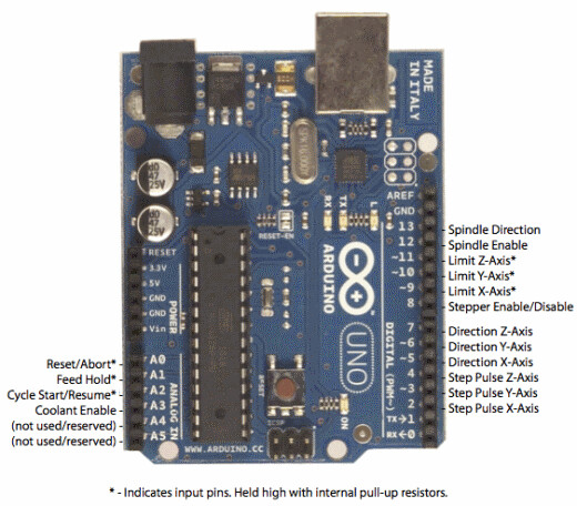
I KNOW, because I have seen the code that GPIO pin 17 corresponds to the Z+ endstop pin on the right hand side of the board, but there are no indications as to:
which pin is which on the shield and
what pins, by number, are suitable for assigning say a relay to, or utilising the A axis as a clone of Y.
Hope someone can clear this up as I cannot find any clear resource on the web.
Do you have a link to information on the board you bought?
There is usually a pin map available for esp32 modules, and then you can “buzz out” at least most of the connections from the module to places on the board with a multimeter set to continuity mode.