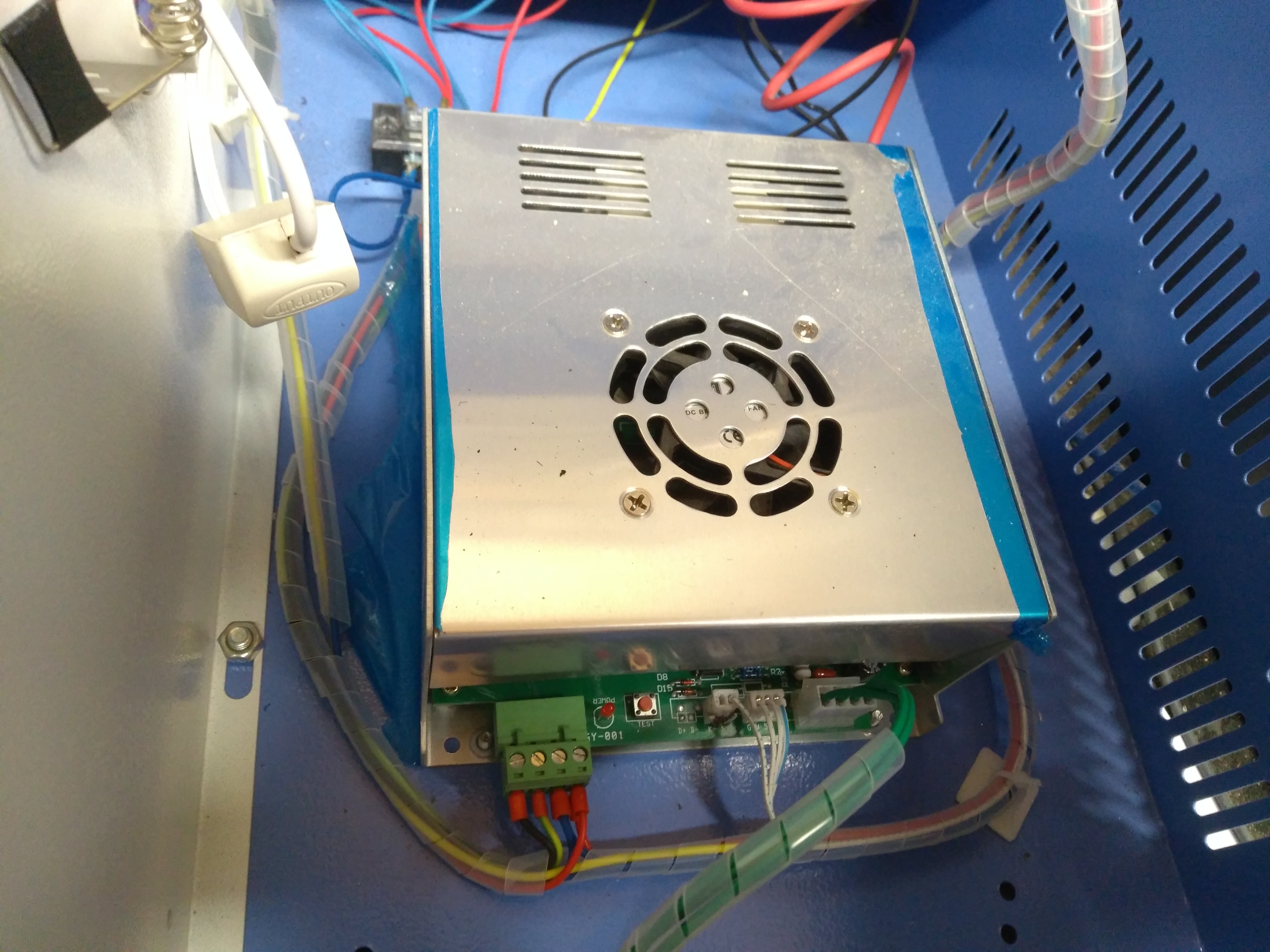
Hi friends. I cannot find any information on where the pins blocking the laser are for an interlock. This psu seems to be differant to others. Some have suggested the main rotary interlock. But that does not allow set up because when you open the lid this will take you back to zero. Any guidance will be appreciated.
Hi Bruce and welcome to the forum. I don’t remember the pin layout for this supply, @donkjr probably will, but if you follow the wires from the laser enable switch one will be P and the other G.
2 Likes
Ah there it is, was looking for this on Don’s site but couldn’t find it for some reason.
Refreshed my memory a bit. So it appears that the laser enable in this supply isn’t wired normally as there is no soldered in pins for D+, D-, which I’ve seen as alternate labels for P+, P-(G). I seem to recall something about this but I can’t find the older discussion.
In your case I think the D+ D- pins are probably jumpered on the other side of the board and the laser enable is controlled through the control board rather than the PSU.
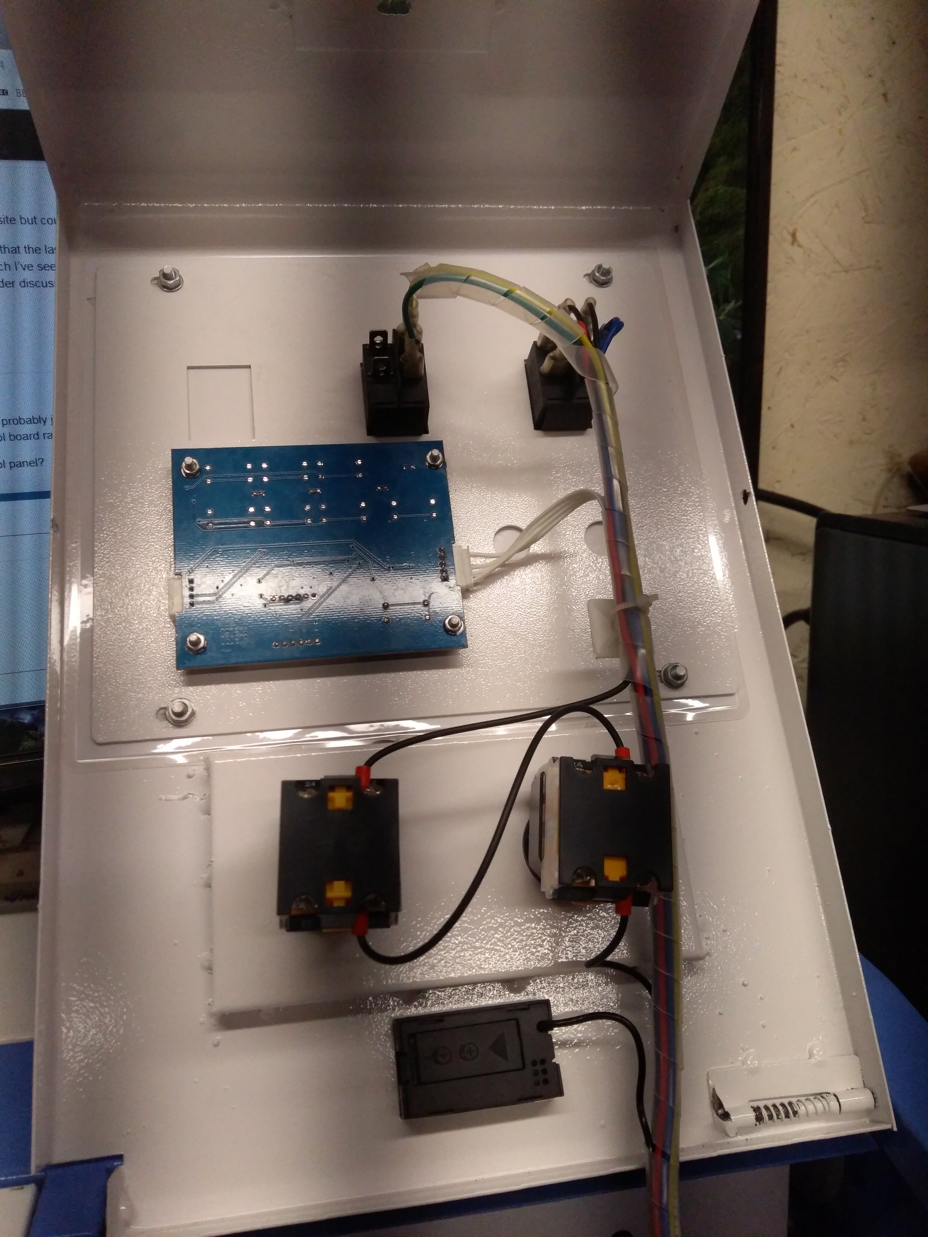
Does your K40 have the digital control panel?
Thanks Michael. I have looked at that but with no p or g outputs i got a bit lost.
The “D” pins generally replace the “P” pins on the supplies like this that I have worked on.
This is the first time I have seen a “D” supply with a digital panel. The D supplies are usually on older machines and the digital panel on newer ones.
My guess is that the D pins on this are shorted out [you can check with ohm meter], and there are no interlocks.
This drawing is for converting supplies but the right hand of the drawing shows how the D pins are connected. Put interlock switched in series with the D and Laser Switch circuit
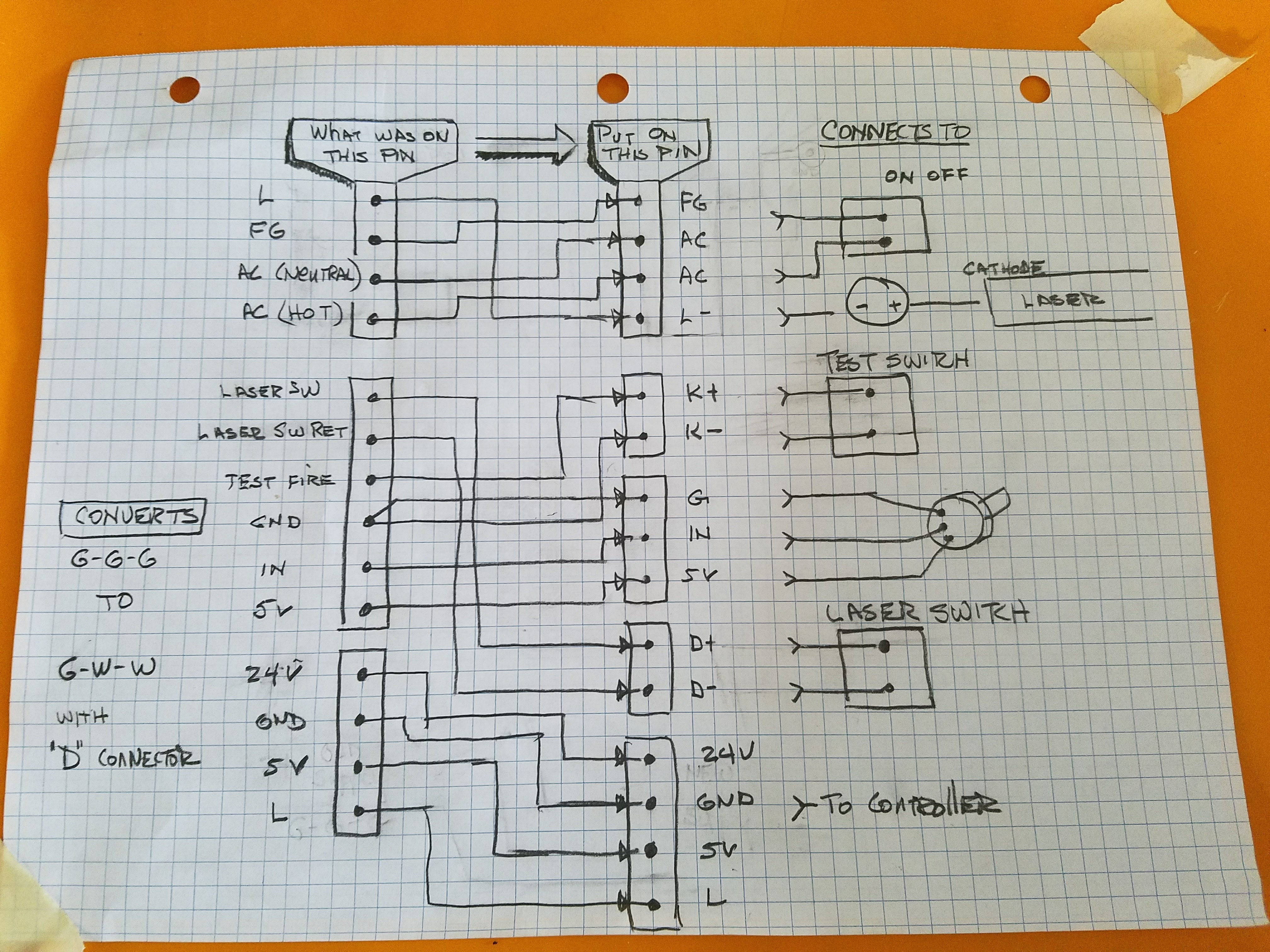
For reference, this drawing shows a standard configuration with P connectors rather than D
The following post explains the operation of the digital panel. There is one exception to note. The panel I have uses the P+ to test-fire the laser, in your configuration that would have been D+. Since there is no P and the D has no connection I must assume [read: guessing] they fire the laser by putting the “Test Switch” in series with the “Laser Switch” and that provides the “IN” signal. i.e. its all done at the panel.
IMO this configuration would manage to make this system even more dangerous than the last configuration!
Editorial comment: all this to save a couple of wires???
(See Assessment in this post)
I would:
- Check that D+ & D- are shorted {if not come back here for more help}
- Remove the short which will require the LPS’s PCB to be disassembled. Not that tough, the biggest challenge is disconnecting/connecting the transistors from the case. Make sure the supply is disconnected!
- Add a connector to D+, D-, alternately solder in a pigtail
- Reassemble the LPS
- Add interlocks and water flow sensor switch in series with the D+ and D- connections
If this works your system will be reasonably safe.
The D+,D- will provide interlock control in spite of the state of the digital panel.
Not knowing what they did at the digital panel may result in a situation where the Laser Switch is on but the interlocks, water sensor are disabling laser fire. This is a good thing from a safety perspective but it may not be obvious why your laser is not firing.
We could think about a way to put an indicator on the interlock circuit if the above works.
2 Likes
thanks don. I will work on that over the weekend.
Don as you can see there are no connections to P+ so I cannot see how connecting it to anything will deactivate the laser.

Thats viewing from the top but i would hazard a guess that the circuit board is multiple layers, either a 2 or 4 layer. the traces for +p and -p may be on the bottom, or sandwiched in between.
2 Likes
Silly me. Nothing on the under side, did not think of multi layer. I will look again tomorrow.
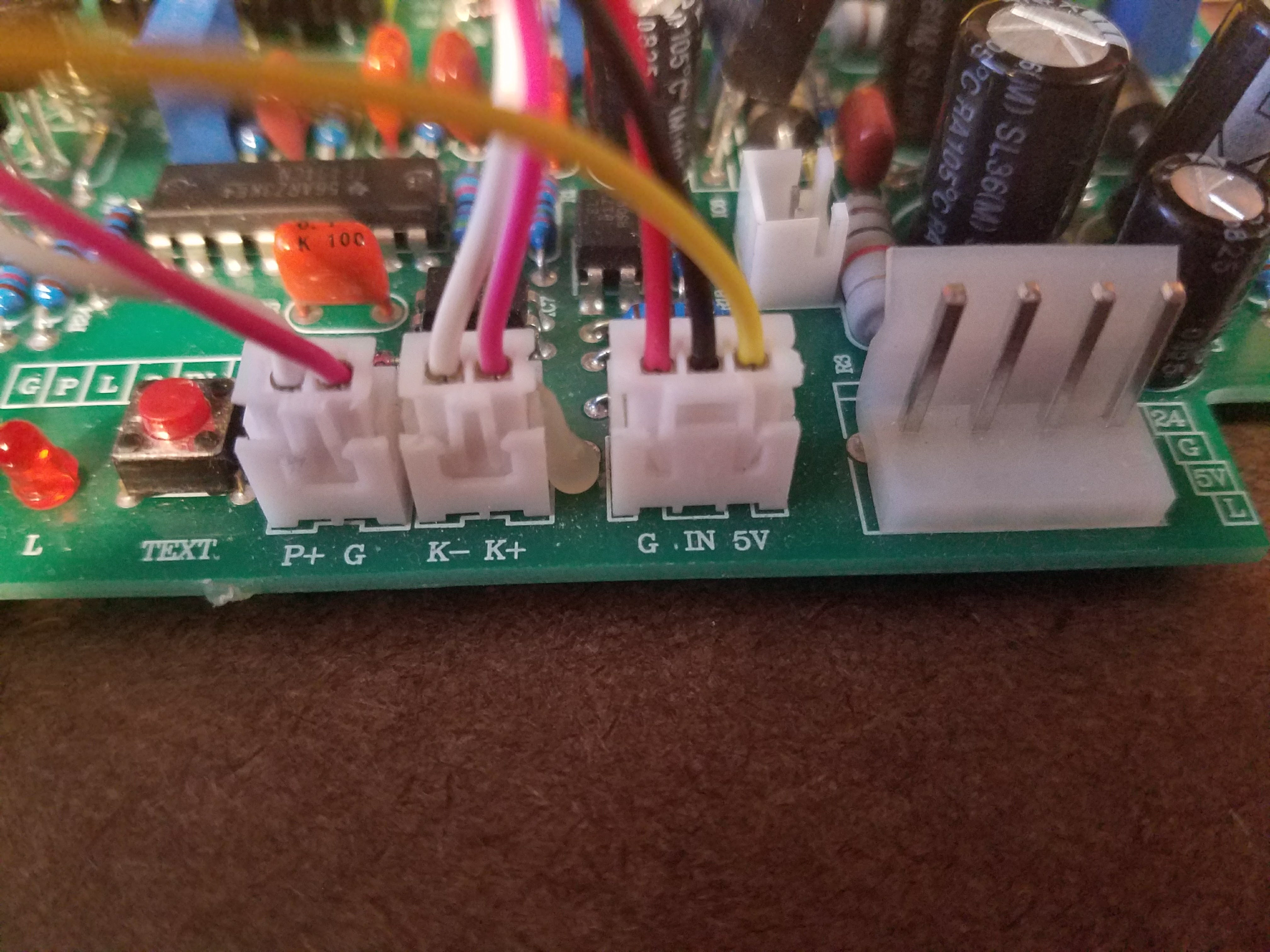
The connector labeled CN7 to the right has the pins/connectors that the silk screen is referencing.
Boy am I confused.
Is that picture from the same supply we started this thread with?
The picture of the supply on the first post is not the type with this connector???
… and we were working on a D+,D- location with no connector not P+,P-?
Hi Don. The first picture was the PSU and yes this is the power led. The d pins and the p pins on the led are shorted.
That’s the d pins on the psu
Just checked and p+/- connect to k- on the psu.
Hi guys. Was there any consensus on where to please the laser cutout switch. I know that Don was confused with the boards and he knows what he’s talking about. So imagine how confused I am. Any help left or is it trial and error time:thinking:
Looking at the control and panel, power supply and pins, here is what I see;
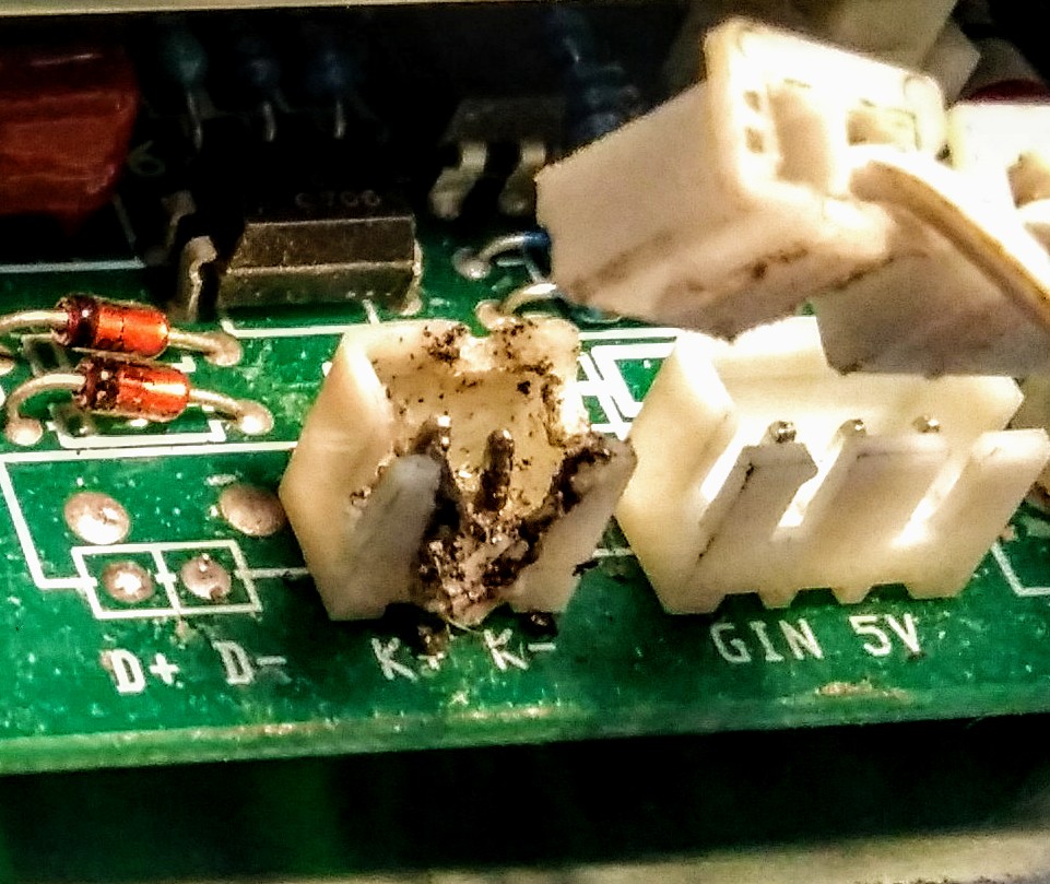
Normally D+/D- is the laser enable and K+/K- is laser test. 4 wires are leaving the control panel. 3 end up on the laser power control pins G, IN, 5V and one to the K- side. Also the K connector has damage.
The manufacture is using the laser test input to fire the laser which means K+ would have to ground to fire the laser. As you can see with Don’s illustrations, not all K connectors are equal. Looks like the polarity is switched. So if the K connector is wired incorrectly, it could cause the damage we see. What I do not see or know is how the power supply enable is accomplished with D connector missing.