As mentioned I’m new here. I’ve had my k40 for a week now. I’ve removed the stock bed pan and have been printing on a ghetto rigged platform comprised of various thickness of wood blocks, cardboard sheets, and shims. As you can imagine, this does not ensure a lot of accuracy. I’m looking for ideas on how to prepare a better bed on a budget. I don’t need stepper actuated auto leveling. I’d be fine with hand adjustments. I also have a 3d printer. I’d like to maximize my engravable surface as much as possible. I plan on cutting the fume extractor back.
What are the best designs for a simple bed replacement?
Awesome guys. Thanks for all the links. I think for now the really simple model from brianvanh might be one I can make quickly and easily. I’ll have to order some belt. I can buy the other parts at Lowe’s.
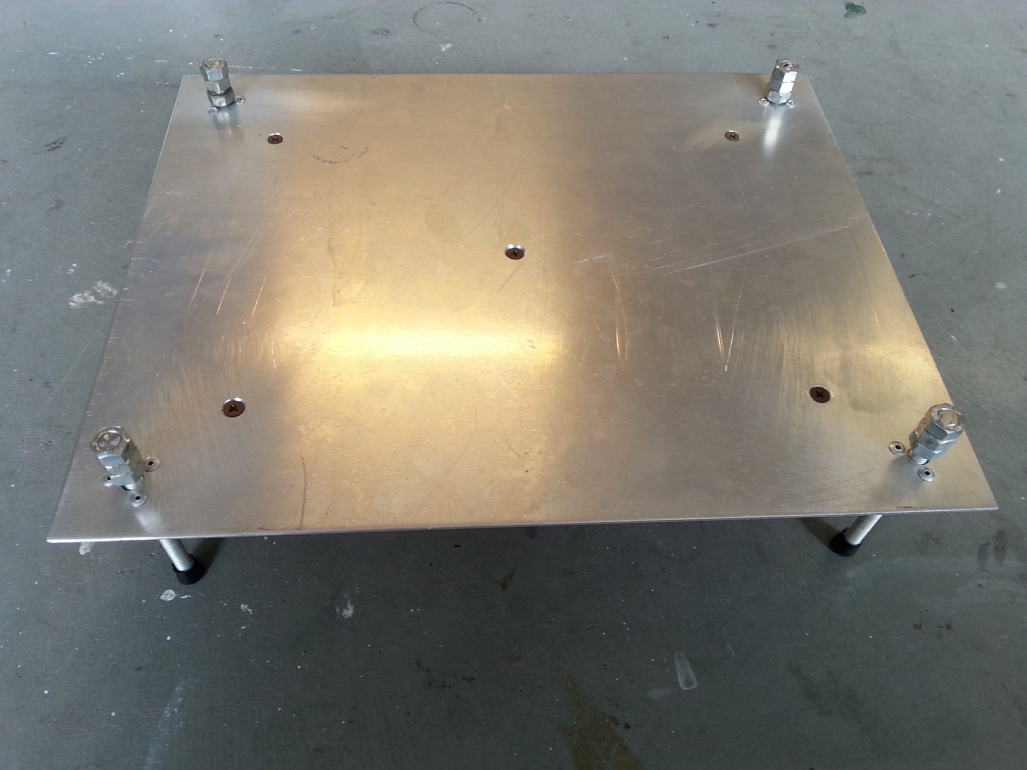
Very simple but I like it too. My only question is what are the 5 screws that form the X pattern for?
Also, you’ve made one of the few beds I’ve seen that is solid with no mesh. Do you find that you get a lot of burnout on the bottom during cuts? What advantages are there to the solid bed?
He’s most likely using a solid bed for rigidity. I imagine he’s got a farme underneath. As is it’s fine for engraving but not so much for cutting. To cut with a solid bed base I would put a piece of Aluminum honeycomb on top. It would provide space for the laser to defocus and any bounce back would be diffuse, especially if you sand the bed plate a bit first.
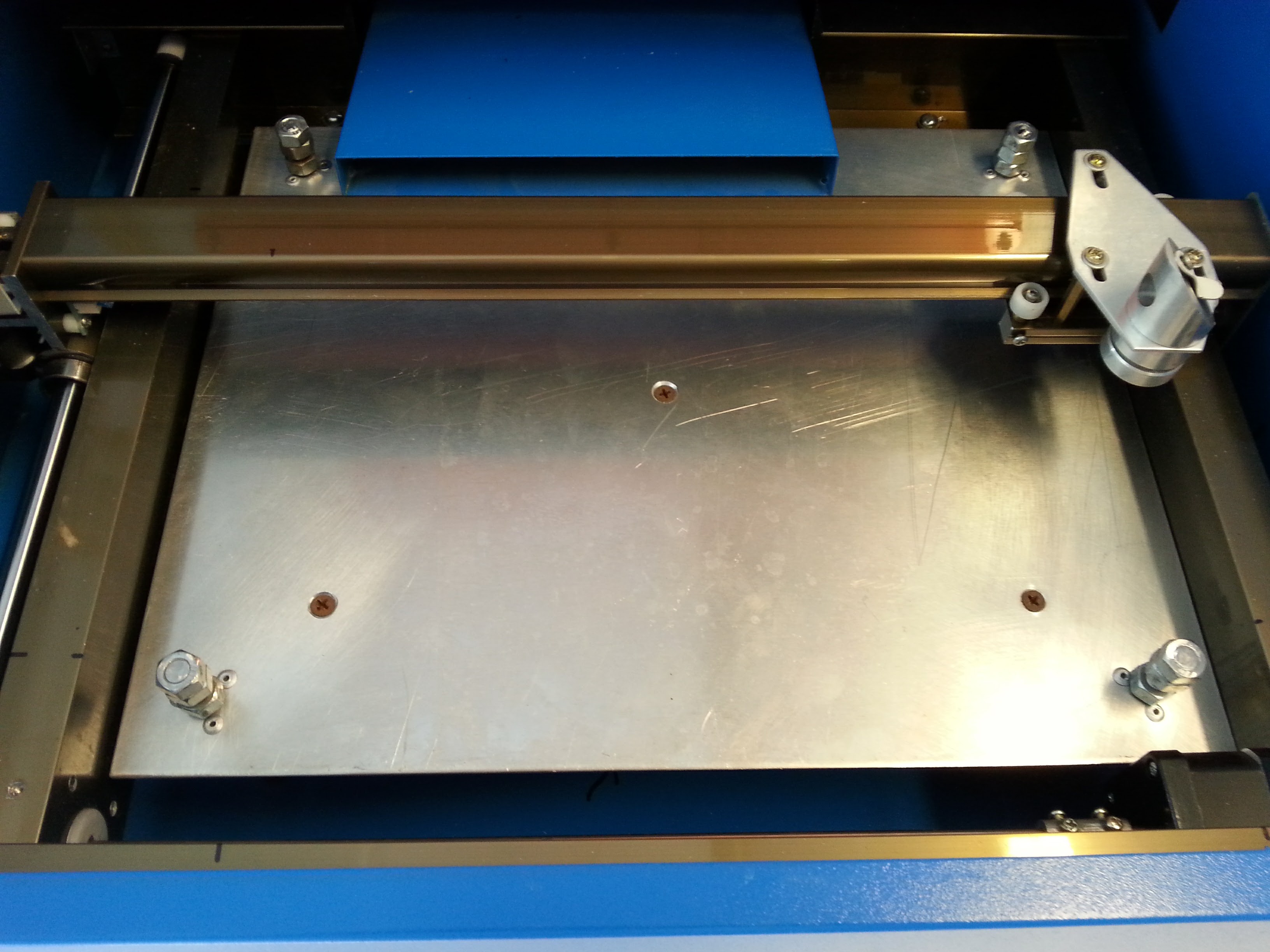
If the bed plate is ferromagnetic (Steel) then you can use magnets to hold pieces in place for engraving.
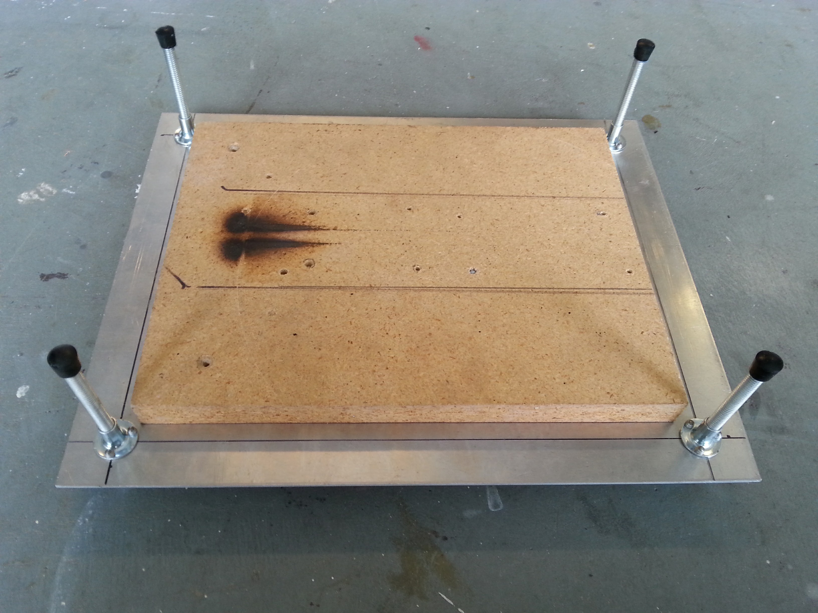
I used a chunk of 3/4" particle board to keep the table square and flat…I cut a piece of bbq grill and use that for the cutting surface. It works just fine.
@MikeMeyer I like simple things like this also but how do you insure it stays level?
Count the turns on each spindle?
I also wonder about the effort to change from thin to large objects?
You have to fiddle with it a bit; I have a bullet level I center on the table after I adjust the cutting height. The cutting height is determined by a rudimentary 50.8 mm gauge the I lased.
A set of 4 gt2 gears and a belt are pretty cheap. But maybe the tension to keep the belt engaged would be too much when the bed was low.
I have been thinking of a desing like you did but with 3D printed sockets at the feet which are held in place with 3 magnets each. Then a be!t system might work and one knob moves it up/down level.
Whoa! I actually like this idea a lot. I had printed out parts for another design but haven’t purchased the support pieces.
I am going to try this design out. A few questions/comments:
I assume there are no issues as far as the printed parts interfering with the gantry slides?
Also, I assume you’ve designed the printed parts to place the subject part at the perfect 50.8mm below the laser? I don’t see any way this can be adjusted without redesigning and reprinting the parts.
I also assume there is some limit to how thick the piece can be. For doing normal flat stock this probably is ideal? For irregular surfaces or very thick materials it may be a challenge.
This design forked from the original @Scorch tried to deal with adjust-ability for the base focus and variable thickness. Haven’t built this yet as my LO table is working great.
Yes, the top of the part is at 50.8mm and the parts do not interfere with the gantry. The left side clips over the rails while the right side clips under and half way on top. It is held in place by the metal bar. Designed in Tinkercad so I can always share the files with you so you can adjust for your laser.
The limit on the thickness is the length of the bolts used minus the bottom metal bar and springs used. The bolts I used almost touch the bottom of my laser. I can push the bottom bar pretty close to the bottom.
I ended up printing the parts but they are too small for my K40. I’d guess the gantry rails on mine are 2-3mm wider and a similar amount taller. I’ll have to redesign the part with the correct dimensions.