I will be giving a tutorial of how I align the gantry on a

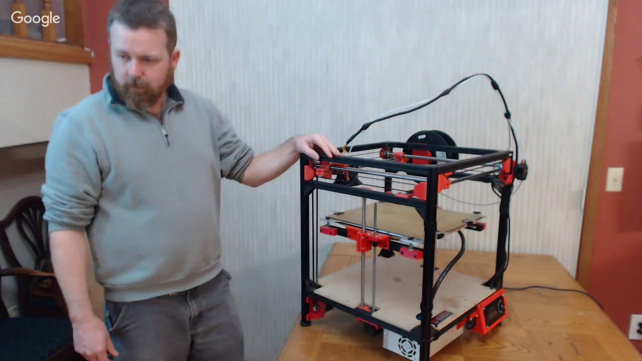
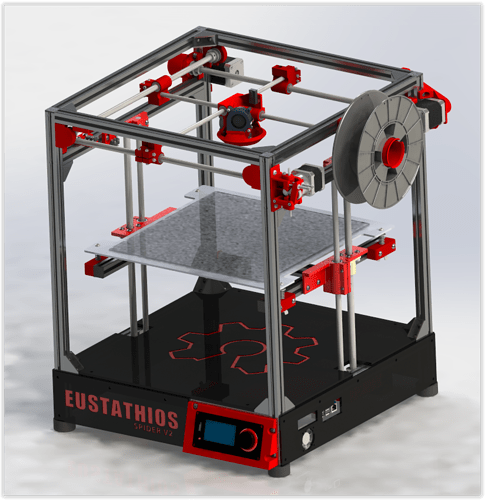
I will be giving a tutorial of how I align the gantry on a Cross Rod XY Gantry style printer. Examples of this style motion platform are the Eustathios and HercuLien 3D printers. I will be purposely misaligning my Eustathios printer, then I will walk through the process to get things back into alignment.

It will take place Tomorrow Saturday December 3rd at 7:30PM Central Time

Tomorrow is Saturday.

@Eclsnowman Awesome!! You rock! I am going to try my best to watch the stream, but it is also my daughter’s 1yr birthday party just before (woohoo!)… so…is it going to be recorded?

Update on my progress: I have ordered all parts for Spider V2.

I made some variations to vendors (went mostly through RobotDigg), I increased the Z height by 75mm (by purchasing a longer ballscrew, rods, and frame).

Also, as I was researching PSU’s, heat beds, aluminum plates, I stumbled across a 300mm PCB MK2a black heatbed on eBay. See here: http://www.ebay.com/itm/282145573486?_trksid=p2057872.m2749.l2649&ssPageName=STRK%3AMEBIDX%3AIT

It was like $40 - so I bought it - and I am going to see if it will do an adequate job replacing the silicone pad/aluminum plate. If so, it would represent a significant cost savings to the BOM. But, I am a total n00b, so it is entirely possible that I just wasted $40… Builders: I certainly appreciate any perspective on this…!

It is a 24V DC heatbed, and I got a 25A SSR DC DC relay on order from RobotDigg, as well as a 350W 24V PSU. I know next to nothing about how to wire this or if this is the even the right relay, etc…

Once the frame is built, and the motion is working properly, I’m sure I will consult the community about this.

If things work out right - I will share my modified BOM with the group in case it is of any value.

I think the bed will be ok. But you will need to find where to mount the second PSU. Because that bed is 350W, your PSU is 350W. You have no headroom to spare on the bed (not generally a good idea), and no extra power for the controller or motors. Myself, I would have stuck with the original design… But that’s just personal preference.

@Edward_Beheler thanks for the catch, yes tomorrow (Saturday). Not Sunday.

Wow, that was a ton of fun. Hope I did ok. I can have a tendency to get on a stream of consciousness and forget what I am doing.

Thanks @Stefano_Pagani ​ for being my Guinea Pig :slight_smile:

If people found this useful, and wanted another video on stuff like this for these style printers… Let me know. But be warned, if you request the vide you are on the hangout with me, these woods are scary walking by yourself :slight_smile:

Also if any of you pixey wranglers out there have a good idea why Stefano is running into the stepper problem let us know (Start of that discussion is around the 21min mark in the stream, and he shows it happening at around 31:50).

Thanks for letting us be apart of the experience. I couldn’t chat due to an you tube account setup issue, but was able to watch. I am just starting my build so the tips and tricks discussed tonight were personally relevant; thanks again for sharing with us (the community) your expertise (@Eclsnowman ) and your experience @Stefano_Pagani1 . We all learned something tonight.

Thanks guys! And thanks Eric for setting this all up!

@Carter_Calhoun any progress on your build? Excited to see things start to come together.

Hey @Eclsnowman - thanks mucho for checking in! Some progress and a question…

I watched your live webcast last weekend and greatly appreciated it- and I also appreciate your offer to do another when the need arises. The webcast was very informative indeed, and I will revisit it in the future.

My build status: All necessary parts ordered, and the final part of the frame comes from Misumi on Tuesday.

For a few of the pricier components, I have alternate components ready as a short term substitute (the electronics, LCD, extruder, hot end, aluminum plate). I will test the unit with the substitutes and purchase the proper ones once this is up and running.

RobotDigg was a great help – they have even more of the components than when you originally created the BOM. If useful, I will share with you how I revised the BOM.

Ordered T Nuts from Aliexpress- but with 12-20 days shipping – and me eager to get going - I ordered these from Amazon:.https://www.amazon.com/gp/product/B01DJ2MPFI/ref=oh_aui_detailpage_o00_s01?ie=UTF8&psc=1

They came today. My concern is that are smaller and seem like they would have less ‘purchase’ or ‘bite’ on the V rail compared to the meatier-looking slide-in nuts.

I tested it out with a bracket and V rail… it seems suitable…so I may just proceed, but appreciate any feedback.

My current ridiculous issue: I have begun printing the parts on my Prusa clone, started with the bearing holder…Bearings definitely don’t fit… I “thought” I had this printer reasonably calibrated (went through the extrusion tutorials and measured some calibration cubes). But, the ID of the bearing holders are all about 21.4 or 21.5mm. And, the bearings are just about 22 OD…So… I have tried forcing them, using a soldering iron to melt around the holder edges, or heat up the bearing. Also tried sanding…None of this really works to my satisfaction.

So…meh… calibrate my clone better? I am using a different filament for these parts than typical… eSun PLA+ Black (which is supposedly several times stronger, recommended higher extrude temp, I use 205). No filament cooling fan present (sadly, my clone is not as such equipped).
I print the bearing holders standing up. Did you print them laying down? If so you are likely seeing the ID drawing down as the plastic shrinks. That’s why I do these parts standing up. I get better dimensional accuracy that way.

I got the bearing holders printed okay - using Walter’s version the bearings fit just fine. For whatever reason, I couldn’t get the dimensions of the stock Eustathio version bearing holders to come out right, they were .5mm too small (tried two separate printers).

Thanks @Eclsnowman , the video helped a lot!

Here are the steps I took:

  1. Do the alignment without motors attached.
  2. Do NOT tighten the belt pulleys on the shafts right away
  3. Get top shafts as close as you can to parallel (use calipers)
  4. Float the bottom shafts, tighten one corner at a time as described
  5. Get belt tension to where you want it
  6. Install two 10mm to 8mm rod alignment spacers
  7. Tighten belt pulleys
  8. Repeat steps 6 & 7 for other axes.

I couldn’t use the alignment spacers on all four sides as the video describes - the Space Invader carriage got in the way and would require longer spacers…

However, tightening the pulleys on the shafts AFTER the cross rods are fixed in place by the rod alignment spacers and AFTER the belts are in tension was key. This helps to get the belt tension on either side of the cross-rod sliders equal.

@Benjamin_Liedblad Yup, that’s the right method. Then running the break in code for an hour or so, then recheck motion by hand (feeling for sticking points). As I have said before… this is the hardest part of the build. But when it’s right, you’ll know.